Advertisement
Quick Links
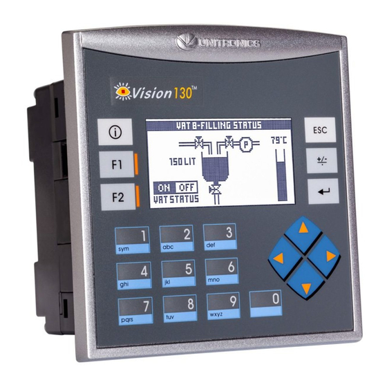
Vision™PLC+HMI
V130-33-TR6/V130-J-TR6
V350-35-TR6/V350-J-TR6
V430-J-RH6
General Description
All of the controllers covered in this guide are micro-PLC+HMIs, rugged programmable logic controllers
that comprise built-in operating panels and on-board I/Os.
Item
On-board I/O
Screen
Keypad
Function Keys
Com Port, Built-in
RS232/485
USB device,
mini-B
Com Ports, separate
order, user-installed
* V430J/V350/V350J comprises both RS232/485 and USB ports; note that only one channel may be used at a time.
Standard Kit Contents
Item
Controller
Terminal Blocks
Battery (installed)
Slides
(2 sets of key labels)
Mounting Brackets
Rubber Seal
Programming cable
+ RS232 adapter
USB
programming cable
Unitronics
Installation Guide
8 Digital Inputs,
including
2 Analog, 1 HSC/Shaft-
encoder inputs
6 Relay Outputs
V130-TR6
V130J-TR6
2.4"
Yes
None
Yes
None
The user may install a CANbus port (V100-17-CAN), and one of the following:
RS232/RS485 port (V100-17-RS4/V100-17-RS4X)
Ethernet (V100-17-ET2)
Profibus Slave (V100-17-PB1)
V130-TR6
V130J-TR6
None
Yes
None
Model Dependent
3.5" Color Touch
Yes
Yes*
None
Yes*
Yes
Yes
Yes
Yes (2 parts)
Yes
4 Analog Inputs (Current)
2 high-speed npn
Transistor Outputs (TR6 Only)
V350-TR6
V350J-TR6
None
Yes
Yes*
Yes*
V350-TR6
V350J-TR6
Yes
None
Yes
V430J-RH6
4.3" Color Touch
Yes*
Yes*
V430J-RH6
None
Yes (4 parts)
1
Advertisement


Need help?
Do you have a question about the Vision V130-TR6 and is the answer not in the manual?
Questions and answers