Unitronics Vision OPLC V130-33-B1 Installation Manual
Hide thumbs
Also See for Vision OPLC V130-33-B1:
- Installtion manual (9 pages) ,
- User manual (16 pages) ,
- User manual (23 pages)
Table of Contents
Advertisement
Quick Links
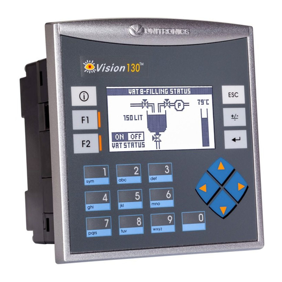
Vision™ OPLC™
The Unitronics V130-33-B1 offers the following features:
I/O configurations can be added via Expansion Modules.
Available by separate order: Ethernet, additional RS232/RS485, CANbus.
General Description
V130 OPLCs are micro-OPLCs, rugged programmable logic controllers that comprise:
Built-in operating panel containing a 2.4" screen and a keypad
Communications
I/O Options
Information Mode
Programming
Software,
& Utilities
Removable
Memory Storage
Data Tables
Unitronics
1 built-in serial port: RS232/RS485
Optional—the user may order and install
one or both of the following modules:
- RS232/RS485/Ethernet
- CANbus
Communication Function Blocks include:
SMS, GPRS, MODBUS serial/IP. Protocol
FB enables PLC to communicate with
almost any external device, via serial or
Ethernet communications
V130 supports digital, high-speed, analog,
weight and temperature measurement
I/Os via:
I/O Expansion Modules
Local or remote I/Os may be added
via expansion port or CANbus.
This mode enables you to:
View & Edit operand values, COM port settings, RTC and screen
contrast/brightness settings
Stop, initialize, and reset the PLC
To enter Information Mode, press the <i> button for several seconds.
The Unitronics Setup CD contains VisiLogic software and other utilities.
VisiLogic
Easily configure hardware and write both HMI and Ladder control
applications; the Function Block library simplifies complex tasks
such as PID. Write your application, and then download it to the
controller via the programming cable included in the kit.
Utilities
Includes UniOPC server, Remote Access for remote programming
and diagnostics, and DataXport for run-time data logging.
To learn how to use and program the controller, as well as use utilities such
as Remote Access, refer to the VisiLogic Help system.
Micro SD card: store datalogs, Alarms, Trends, Data Tables; export to Excel;
backup Ladder, HMI & OS and use this data to 'clone' PLCs.
For more data, refer to the SD topics in the VisiLogic Help system.
Data tables enable you to set recipe parameters and create datalogs.
V130-33-B1
Installation Guide
1
Advertisement
Table of Contents

Related Manuals for Unitronics Vision OPLC V130-33-B1


Summary of Contents for Unitronics Vision OPLC V130-33-B1
- Page 1 Stop, initialize, and reset the PLC To enter Information Mode, press the <i> button for several seconds. Programming The Unitronics Setup CD contains VisiLogic software and other utilities. Software, VisiLogic & Utilities Easily configure hardware and write both HMI and Ladder control applications;...
- Page 2 All examples and diagrams are intended to aid understanding, and do not guarantee operation. Unitronics accepts no responsibility for actual use of this product based on these examples. Please dispose of this product according to local and national standards and regulations.
- Page 3 4. Tighten the bracket screws against the panel. Hold the bracket securely against the unit while tightening the screw. 5. When properly mounted, the controller is squarely situated in the panel cut-out as shown in the figure to the right. Unitronics...
- Page 4 Input or output cables should not be run through the same multi-core cable or share the same wire. Allow for voltage drop and noise interference with input lines used over an extended distance. Use wire that is properly sized for the load. The controller and I/O signals must be connected to the same 0V signal. Unitronics...
- Page 5 By factory default, the port is set to RS232, termination ON. Use RS232 to download programs from a PC, and to communicate with serial devices and applications, such as SCADA. Use RS485 to create a multi-drop network containing up to 32 devices. Unitronics...
- Page 6 To change the communication setting to RS485, both communication standard jumpers must be moved. To change the RS485 termination, both termination jumpers must be moved. To access the jumpers, you must open the controller according to the instructions beginning on page 7. Unitronics...
- Page 7 Vision™ OPLC™ Opening the Controller Before performing these actions, touch a grounded object to discharge any electrostatic charge. Avoid touching the PCB board directly. Hold the PCB board by its connectors. 1. Turn off the power supply, disconnect, and dismount the controller. 2.
Need help?
Do you have a question about the Vision OPLC V130-33-B1 and is the answer not in the manual?
Questions and answers