Advertisement
Quick Links
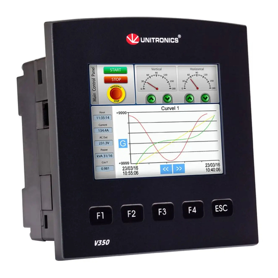
Vision™PLC+HMI
V130-33-T2/V130-J-T2
V350-35-T2/V350-J-T2
V430-J-T2
General Description
The products listed above are micro-PLC+HMIs, rugged programmable logic controllers that comprise
built-in operating panels.
Detailed Installation Guides containing the I/O wiring diagrams for these models, technical specifications,
and additional documentation are located in the Technical Library in the Unitronics website:
https://unitronicsplc.com/support-technical-library/
Item
On-board I/O
Screen
Keypad
Function Keys
Com Port, Built-in
RS232/485
USB device,
mini-B
Com Ports, separate
order, user-installed
* V430J/V350/V350J comprises both RS232/485 and USB ports; note that only one channel may be used at a time.
Standard Kit Contents
Item
Controller
Terminal Blocks
Battery (installed)
Slides
(2 sets of key labels)
Mounting Brackets
Rubber Seal
Unitronics
User Guide
▪
12 Digital Inputs, including 2 Analog,
3 HSC/Shaft-encoder inputs
▪
12 Transistor Outputs
V130-T2
V130J-T2
2.4"
Yes
None
Yes
None
The user may install a CANbus port (V100-17-CAN), and one of the following:
•
RS232/RS485 port (V100-17-RS4/V100-17-RS4X)
•
Ethernet (V100-17-ET2)
•
Profibus Slave (V100-17-PB1)
V130-T2
V130J-T2
None
Model Dependent
3.5" Color Touch
Yes
Yes*
None
Yes*
Yes
Yes
Yes
Yes (2 parts)
Yes
V350-T2
V350J-T2
None
Yes
Yes*
Yes*
V350-T2
V350J-T2
Yes
V430J-T2
4.3" Color Touch
Yes*
Yes*
V430J-T2
None
Yes (4 parts)
1
Advertisement

Subscribe to Our Youtube Channel
Related Manuals for Unitronics Vision V130-T2


Summary of Contents for Unitronics Vision V130-T2
- Page 1 The products listed above are micro-PLC+HMIs, rugged programmable logic controllers that comprise built-in operating panels. Detailed Installation Guides containing the I/O wiring diagrams for these models, technical specifications, and additional documentation are located in the Technical Library in the Unitronics website: https://unitronicsplc.com/support-technical-library/ V130-T2...
- Page 2 ▪ All examples and diagrams are intended to aid understanding, and do not guarantee operation. Unitronics accepts no responsibility for actual use of this product based on these examples. ▪ Please dispose of this product according to local and national standards and regulations.
- Page 3 4. Tighten the bracket’s screws against the panel. Hold the bracket securely against the unit while tightening the screw. 5. When properly mounted, the controller is squarely situated in the panel cut-out as shown in the accompanying figures. V130/V350/V130J/V350J Unitronics...
- Page 4 DIN-rail as shown in the figure to the right. UL Compliance The following section is relevant to Unitronics’ products that are listed with the UL. The following models: V130-33-R34, V130-J-R34, V130-T4-ZK1, V350-35-RA22, V350-J-RA22, V350-35-R34, V350-J-R34, V430-J-R34 are UL listed for Hazardous Locations.
- Page 5 Class I, Division 2, Groups A, B, C and D These Release Notes relate to all Unitronics products that bear the UL symbols used to mark products that have been approved for use in hazardous locations, Class I, Division 2, Groups A, B, C and D.
- Page 6 à risques, Class I, Division 2, Groups A, B, C et D. Cette note fait référence à tous les produits Unitronics portant le symbole UL - produits qui ont été certifiés pour une utilisation dans des endroits dangereux, Classe I, Division 2, Groupes A, B, C et D.
- Page 7 - Inputs 1, 3 and 5 can function as either counter reset, as part of a shaft-encoder, or as normal digital inputs. If inputs 0, 2 and 4 are set as high-speed counters (without reset), inputs 1, 3 and 5 can function as normal digital inputs. Unitronics...
- Page 8 Inputs 10/11: Set as Digital or Analog Set to JP5 (Input 10) JP6 (Input 11) Digital* Analog Analog Inputs AN0/AN1: Set Type Set to JP3 (AN0) JP4 (AN1) Voltage* Current *Default settings I/O Wiring npn (sink) Input Input wiring HSC input wiring Unitronics...
- Page 9 HSC input wiring Shaft-encoder Analog Input Analog input wiring, current (2/3-wire) Analog input wiring, current (4-wire), Voltage ▪ Shields should be connected at the signal’s source. ▪ The 0V signal of the analog input must be connected to the controller’s 0V. Unitronics...
- Page 10 To maximize system performance, avoid electromagnetic interference by: ▪ Mounting the controller on a metal panel. ▪ Connect each common and ground connection directly to the earth ground of your system. ▪ For ground wiring uses the shortest and thickest possible wire. Unitronics...
- Page 11 To do so, remove the RS485 connector (pins 1 & 6) from the PLC and connect a standard RS232 programming cable. Note that this is possible only if DTR and DSR signals of RS232 are not used (which is the standard case). Unitronics...
- Page 12 ** Causes the unit to function as an end unit in an RS485 network USB Port ▪ The USB port is not isolated. Caution Make sure that the PC and the controller are grounded to same potential. The USB port may be used for programming, OS download, and PC access. Unitronics...
- Page 13 Do not force the board into place; doing so may damage the controller. 2. Replace the back cover of the controller and fasten the corner screws. Note that you must replace the back cover securely before powering up the controller. Unitronics...
- Page 14 PLC with Flat panel, Color touch display 3.5’’ V350-J-T2 PLC with Flat panel, Color touch display 4.3’’ V430-J-T2 You can find additional information, such as wiring diagrams, in the product’s installation guide located in the Technical Library at www.unitronics.com. Power Supply V130-T2 V350-T2 V430J-T2...
- Page 15 0.9% Yes – if an analog input deviates above the permissible range, its value will be Status indication 1024. Notes: 4. For example, if 2 inputs are configured as analog, it takes 2 scans to update all analog values. Unitronics...
- Page 16 Keypad Slides.pdf. keys. Refer to V130 Two sets of slides are Keypad Slides.pdf. supplied with the A complete set of controller: one set of blank slides is arrow keys, and one available by separate blank set. order Unitronics...
- Page 17 Vision™PLC+HMI Unitronics...
- Page 18 Removable Memory Micro SD card Compatible with standard SD and SDHC; up to 32GB store datalogs, Alarms, Trends, Data Tables, backup Ladder, HMI, and OS. See Note 6 Notes: 6.User must format via Unitronics SD tools utility. Unitronics...
- Page 19 - An additional port (Port 2). Available port types: RS232/RS485 isolated/non-isolated, Ethernet - A CANbus port Port module documentation is available on the Unitronics website. 9. Note that physically connecting a PC to the controller via USB suspends RS232/RS485 communications via Port 1.
- Page 20 8.4Hz to 150Hz, 1G acceleration. The information in this document reflects products at the date of printing. Unitronics reserves the right, subject to all applicable laws, at any time, at its sole discretion, and without notice, to discontinue or change the features, designs, materials and other specifications of its products, and to either permanently or temporarily withdraw any of the forgoing from the market.
Need help?
Do you have a question about the Vision V130-T2 and is the answer not in the manual?
Questions and answers