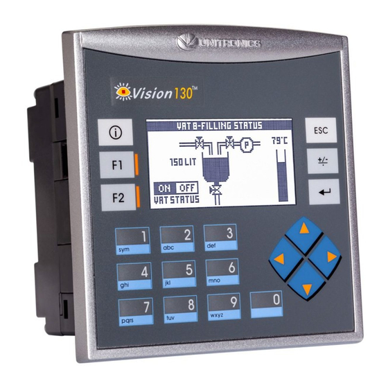
Unitronics Vision OPLC V130-J-TR20 Installation Manual
Hide thumbs
Also See for Vision OPLC V130-J-TR20:
- Installation manual (12 pages) ,
- User manual (23 pages)
Table of Contents
Advertisement
Quick Links
Vision™ OPLC™
V130-33-TR20/V130-J-TR20
V350-35-TR20/V350-J-TR20
V430-J-RH2
General Description
All of the controllers covered in this guide are micro-OPLCs, rugged programmable logic controllers that
comprise built-in operating panels and on-board I/Os.
Item
On-board I/O
Screen
Keypad
Function Keys
Com Port, Built-in
RS232/485
USB device,
mini-B
Com Ports, separate
order, user-installed
* V430J comprises both RS232/485 and USB ports; note that only one channel may be used at a time.
Standard Kit Contents
Item
Controller
Terminal Blocks
Battery (installed)
Slides
(2 sets of key labels)
Mounting Brackets
Rubber Seal
Programming cable
+ RS232 adapter
USB
programming cable
Unitronics
Installation Guide
12 Digital Inputs, including 2 Analog,
3 HSC/Shaft-encoder inputs
6 Relay Outputs
V130-TR20
V130J-TR20
2.4"
Yes
None
Yes
None
The user may install a CANbus port (V100-17-CAN), and one of the following:
RS232/RS485 port (V100-17-RS4/V100-17-RS4X)
•
Ethernet (V100-17-ET2)
•
Profibus Slave (V100-17-PB1)
•
V130-TR20
V130J-TR20
None
2 high-speed npn Transistor Outputs
(TR20 Only)
Model Dependent
3.5" Color Touch
Yes
Yes
None
None
Yes
Yes
Yes
Yes (2 parts)
Yes
Yes
None
V350-TR20
V350J-TR20
None
Yes
Yes
None
V350-TR20
V350J-TR20
Yes
V430J-RH2
4.3" Color Touch
Yes*
Yes*
V430J-RH2
None
Yes (4 parts)
None
Yes
1
Advertisement
Table of Contents

Subscribe to Our Youtube Channel
Summary of Contents for Unitronics Vision OPLC V130-J-TR20
- Page 1 Standard Kit Contents V130-TR20 V350-TR20 V430J-RH2 Item V130J-TR20 V350J-TR20 Controller Terminal Blocks Battery (installed) Slides None None (2 sets of key labels) Mounting Brackets Yes (2 parts) Yes (4 parts) Rubber Seal Programming cable None + RS232 adapter None programming cable Unitronics...
-
Page 2: Alert Symbols And General Restrictions
All examples and diagrams are intended to aid understanding, and do not guarantee operation. Unitronics accepts no responsibility for actual use of this product based on these examples. Please dispose of this product according to local and national standards and regulations. -
Page 3: Panel Mounting
4. Tighten the bracket’s screws against the panel. Hold the bracket securely against the unit while tightening the screw. 5. When properly mounted, the controller is squarely situated in the panel cut-out as shown in the accompanying figures. V130/V350/V130J/V350J Unitronics... - Page 4 DIN-rail Mounting (V130/V350/V130J/V350J) 1. Snap the controller onto the DIN rail as shown in the figure to the right. 2. When properly mounted, the controller is squarely situated on the DIN-rail as shown in the figure to the right. Unitronics...
-
Page 5: Wiring Procedure
- Inputs 1, 3, and 5 can function as either counter reset, as part of a shaft-encoder, or as normal digital inputs. If inputs 0, 2, 4 are set as high-speed counters (without reset), inputs 1, 3, 5 can function as normal digital inputs. Unitronics... - Page 6 Inputs 10/11: Set as Digital or Analog Set to JP5 (Input 10) JP6 (Input 11) Digital* Analog Analog Inputs AN0/AN1: Set Type Set to JP3 (AN0) JP4 (AN1) Voltage* Current *Default settings I/O Wiring npn (sink) Input Input wiring HSC input wiring Unitronics...
- Page 7 HSC input wiring Shaft-encoder Analog Input Analog input wiring, current (2/3-wire) Analog input wiring, current (4-wire), voltage Shields should be connected at the signal’s source. The 0V signal of the analog input must be connected to the controller’s 0V. Relay Outputs Unitronics...
-
Page 8: Power Supply
To maximize system performance, avoid electromagnetic interference by: Mounting the controller on a metal panel. Connect each common and ground connection directly to the earth ground of your system. For ground wiring uses the shortest and thickest possible wire. Unitronics... - Page 9 To do so, remove the RS485 connector (pins 1 & 6) from the PLC and connect a standard RS232 programming cable. Note that this is possible only if DTR and DSR signals of RS232 are not used (which is the standard case). Unitronics...
- Page 10 ** Causes the unit to function as an end unit in an RS485 network USB Port The USB port is not isolated. Caution Make sure that the PC and the controller are grounded to same potential. The USB port may be used for programming, OS download, and PC access. Unitronics...
-
Page 11: Opening The Controller
Vision™ OPLC™ Opening the Controller Before performing these actions, touch a grounded object to discharge any electrostatic charge. Avoid touching the PCB board directly. Hold the PCB board by its connectors. 1. Turn off the power supply, disconnect, and dismount the controller. 2.


Need help?
Do you have a question about the Vision OPLC V130-J-TR20 and is the answer not in the manual?
Questions and answers