HMS Networks Intesis IN770AIR00SO000 User Manual
Air gateway
Hide thumbs
Also See for Intesis IN770AIR00SO000:
- Manual (69 pages) ,
- User manual (50 pages) ,
- Installation manual (2 pages)

Related Manuals for HMS Networks Intesis IN770AIR00SO000


Summary of Contents for HMS Networks Intesis IN770AIR00SO000
- Page 1 ENGLISH 700series Air Gateway - IN770AIR⁎⁎⁎O000 SAMSUNG NASA VRF SYSTEMS to Modbus, KNX, BACnet, and Home Automation USER MANUAL Version 1.0.12 Publication date 2024-09-04...
- Page 2 The information in this document shall therefore not be construed as a commitment on the part of HMS Networks and is subject to change without notice. HMS Networks makes no commitment to update or keep current the information in this document.
-
Page 3: Table Of Contents
700series Air Gateway - IN770AIR⁎⁎⁎O000 Table of Contents 1. Description, Compatible AC systems, and Order Codes ..............1 2. Licensing ..........................2 3. General Information ........................ 3 3.1. Intended Use of the User Manual ..................3 3.2. General Safety Information ....................3 3.3. -
Page 4: Description, Compatible Ac Systems, And Order Codes
Description, Compatible AC systems, and Order Codes 700series Air Gateway - IN770AIR⁎⁎⁎O000 1. Description, Compatible AC systems, and Order Codes IN770AIR⁎⁎⁎O000 Gateway. Modbus®, KNX®, BACnet®, and Home Automation gateway for Samsung® HVAC systems. This gateway is compatible with NASA VRF units commercialized by Samsung. Use the compatibility tool to get a complete list of compatible units: https://compatibility.intesis.com/ You can set up this Intesis gateway for Modbus TCP, Modbus RTU, KNX TP, BACnet/IP, BACnet MS/TP, or Home... -
Page 5: Licensing
700series Air Gateway - IN770AIR⁎⁎⁎O000 Licensing 2. Licensing Distribution license(s) for the IN770AIR⁎⁎⁎O000 gateway: Maximum AC units Order Code License Indoor units Outdoor units IN770AIRXXSO000 IN770AIR00SO000 Small IN770AIR00MO000 Medium NOTE The order code may vary depending on the product seller and the buyer's location. Page 2 of 50 USER MANUAL Version 1.0.12... -
Page 6: General Information
General Information 700series Air Gateway - IN770AIR⁎⁎⁎O000 3. General Information 3.1. Intended Use of the User Manual This manual contains the main features of this Intesis gateway and the instructions for its appropriate installation, configuration, and operation. Any person who installs, configures, or operates this gateway or any associated equipment should be aware of this manual's contents. -
Page 7: Admonition Messages And Symbols
700series Air Gateway - IN770AIR⁎⁎⁎O000 Admonition Messages and Symbols This Intesis gateway is designed for installation in an enclosure. When the device is mounted outside an enclosure, precautions should be taken to avoid electrostatic discharges to the unit in environments with static levels above 4 kV. -
Page 8: Overview
Overview 700series Air Gateway - IN770AIR⁎⁎⁎O000 4. Overview This IN770AIR⁎⁎⁎O000 gateway supports four combinations. Gateway's client interface ↔ Gateway's server interface Modbus TCP and RTU KNX TP Samsung NASA systems BACnet/IP or MS/TP Home Automation IMPORTANT This document assumes that the user is familiar with these technologies. Figure 1. -
Page 9: Inside The Package
700series Air Gateway - IN770AIR⁎⁎⁎O000 Inside the Package Figure 3. Integration of Samsung units into BACnet systems Figure 4. Integration of Samsung units into Home Automation systems 4.1. Inside the Package ITEMS INCLUDED • Intesis IN770AIR⁎⁎⁎O000 Gateway • USB Mini-B type to USB Type-A cable •... -
Page 10: Gateway General Functionality
Gateway General Functionality 700series Air Gateway - IN770AIR⁎⁎⁎O000 • Scan function: Find the AC units connected to the air conditioning bus. • Specific signals to monitor outdoor units. • 2 x DIP switches for the EIA-485 connector termination and polarization configuration. •... -
Page 11: Quick Start Guide
700series Air Gateway - IN770AIR⁎⁎⁎O000 Quick Start Guide 5. Quick Start Guide IMPORTANT While the following procedure outlines the fundamental steps for installing, wiring, and configuring the gateway, it is crucial to thoroughly review all documentation to prevent errors. Install Intesis MAPS on your laptop. -
Page 12: Samsung Network Setup
Samsung Network Setup 700series Air Gateway - IN770AIR⁎⁎⁎O000 6. Samsung Network Setup Before integrating the IN770AIR⁎⁎⁎O000 gateway into the HVAC system, you must first perform some actions to properly set up the Samsung NASA VRF network. IMPORTANT Read the documentation provided with the Samsung NASA system to learn the specific procedures needed for this setup and seek guidance from your Samsung provider. - Page 13 700series Air Gateway - IN770AIR⁎⁎⁎O000 Samsung Network Setup Also, the Console viewer shows the output Samsung initialized after booting up the gateway, as shown in the picture below: NOTE This console output may take a few minutes to display. Page 10 of 50 USER MANUAL Version 1.0.12...
-
Page 14: Hardware
Hardware 700series Air Gateway - IN770AIR⁎⁎⁎O000 7. Hardware 7.1. Mounting IMPORTANT Before mounting, please ensure that the chosen installation place preserves the gateway from direct solar radiation, water, high relative humidity, or dust. NOTE Mount the gateway on a wall or over a DIN rail. We recommend the DIN rail mounting option, preferably inside a grounded metallic industrial cabinet. -
Page 15: Din Rail Mounting
700series Air Gateway - IN770AIR⁎⁎⁎O000 Mounting DIN RAIL MOUNTING Keep the clips in their original position. Fit the gateway’s top-side clips in the upper edge of the DIN rail. Press the low side of the gateway gently to lock it in the DIN rail. Make sure the gateway is firmly fixed. -
Page 16: Connection
Connection 700series Air Gateway - IN770AIR⁎⁎⁎O000 7.2. Connection CAUTION Disconnect all systems from power before manipulating and connecting them to the gateway. IMPORTANT Keep communication cables away from power and ground wires. 7.2.1. Gateway Connectors Figure 5. Wiring diagram USER MANUAL Version 1.0.12 Page 13 of 50... -
Page 17: Wiring The Connectors
700series Air Gateway - IN770AIR⁎⁎⁎O000 Connection WIRING THE CONNECTORS IMPORTANT For all connectors, use solid or stranded wires (twisted or with ferrule). Cross-section/gauge per terminal: • One core: 0.2 .. 2.5 mm / 24 .. 11 AWG • Two cores: 0.2 .. 1.5 mm / 24 .. -
Page 18: Connection To The Ac Unit
Connection 700series Air Gateway - IN770AIR⁎⁎⁎O000 7.2.2. Connection to the AC Unit Connect the Samsung air conditioning network bus (R1/R2) to the gateway using the B1 and B2 poles of the AC-Port B. IMPORTANT Observe polarity: • B1: R2 • B2: R1 •... -
Page 19: Connection To Knx
700series Air Gateway - IN770AIR⁎⁎⁎O000 Connection IMPORTANT Observe polarity. IMPORTANT Observe the standard restrictions of the EIA-485 bus: • Maximum distance of 1200 meters (0.75 miles). • Maximum of 32 devices connected to the bus. • A 120 ohms (Ω) termination resistor is needed at each end of the bus. The gateway has an internal bus biasing circuit incorporating the termination resistor. - Page 20 Connection 700series Air Gateway - IN770AIR⁎⁎⁎O000 • Connecting to a hub or switch of the LAN of the building: use a straight Ethernet UTP/FTP CAT5 or higher cable. NOTE When commissioning the gateway for the first time, DHCP will be enabled for 30 seconds. During that time, if there is a DHCP server, an IP address will be automatically assigned to the gateway.
-
Page 21: Connection To Home Automation
700series Air Gateway - IN770AIR⁎⁎⁎O000 Connection 7.2.6. Connection to Home Automation Connect the Home Automation Ethernet cable to the gateway's Ethernet Port. The correct cable to use depends on where the gateway is connected: • Connecting directly to a Home Automation device: use a crossover Ethernet UTP/FTP CAT5 or higher cable. •... -
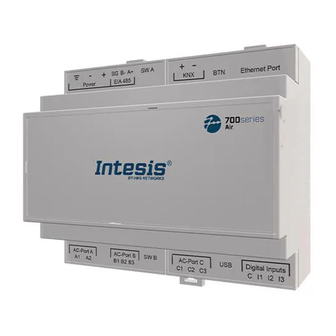
Page 22: Gateway Layout
Gateway Layout 700series Air Gateway - IN770AIR⁎⁎⁎O000 7.3. Gateway Layout Figure 6. Disposition of hardware elements in the gateway Plastic covers numbered in the image as ①, ②, ③, and ④ can be easily disassembled. NOTE LEDs and DIP switches are hidden behind the removable plastic covers and can only be accessed by disassembling the covers. -
Page 23: Led Indicators
700series Air Gateway - IN770AIR⁎⁎⁎O000 LED Indicators 7.4. LED Indicators Table 1. LEDs location and behavior Cover Color Description Top side LED 1 (PWR) Green Power on (not programmable) LED 2 (ERR) Blinking: Hardware error Under frontal cover ① LED 3 Green 485 Tx (RS485 for BACnet or Modbus) LED 4... -
Page 24: Dip Switches
DIP Switches 700series Air Gateway - IN770AIR⁎⁎⁎O000 7.5. DIP Switches The gateway has two DIP switches (see the figure Disposition of hardware elements in the gateway (page 19)): • DIP switch A (SW A) • DIP switch B (SW B) Each DIP switch is dedicated to a 485 port, and its function is to activate or deactivate the termination resistor (position 1) and the polarization (positions 2 and 3) of each port: Position... -
Page 25: Technical Specifications
700series Air Gateway - IN770AIR⁎⁎⁎O000 Technical Specifications 7.7. Technical Specifications Plastic, type PC (UL 94 V-0). Color: Light Grey. RAL 7035 Housing Net dimensions (HxWxD): Millimeters: 90 x 106 x 58 mm / Inches: 3.5 x 4.2 x 2.3" Wall: Use M3 25 mm (1") length screws. Secure mounting: below 2 meters (6 feet) Mounting DIN rail (recommended mounting) EN60715 TH35 Wire cross-section/gauge per terminal:... -
Page 26: Dimensions
Dimensions 700series Air Gateway - IN770AIR⁎⁎⁎O000 7.8. Dimensions NET DIMENSIONS (HxWxD) Millimeters: 90 x 106 x 58 mm Inches: 3.5 x 4.2 x 2.3" IMPORTANT Leave enough clear space to wire the gateway easily and for the subsequent manipulation of elements. -
Page 27: Available Protocol Combinations
700series Air Gateway - IN770AIR⁎⁎⁎O000 Available Protocol Combinations 8. Available Protocol Combinations 8.1. Integration into Modbus Systems 8.1.1. Modbus Registers NOTICE This part is common for Modbus RTU and TCP. Functions to read Modbus registers: • 03 Read Holding Registers. •... - Page 28 Integration into Modbus Systems 700series Air Gateway - IN770AIR⁎⁎⁎O000 Register name Possible values Modbus address Cool: 18 .. 30 °C / 64 .. 86°F Temperature Setpoint (all the units) (x10°C) Heat: 16 .. 30 °C / 61 .. 86° Vent. On (all the units) 1: Set Vent.
- Page 29 700series Air Gateway - IN770AIR⁎⁎⁎O000 Integration into Modbus Systems Register name Possible values Modbus address formula Celsius: 8 .. 25°C Discharge Setpoint Temp.. Cool AHU (IU address[1..64] × 100) + 7 R, W (x10°C) Fahrenheit: 46 .. 77°F Celsius: 30 .. 43°C Discharge Setpoint Temp.
- Page 30 Integration into Modbus Systems 700series Air Gateway - IN770AIR⁎⁎⁎O000 Register name Possible values Modbus address formula Water In Temp (x10°C) °C / °F (IU address[1..64] × 100) + 28 Water Out Temp (x10°C) °C / °F (IU address[1..64] × 100) + 29 Cool: 5 ..
-
Page 31: Integration Into Knx Systems
700series Air Gateway - IN770AIR⁎⁎⁎O000 Integration into KNX Systems 8.2. Integration into KNX Systems 8.2.1. KNX Signals The following tables list all available KNX signals for this gateway. NOTE Physical Address: The gateway supports (P/S) and (P/I/S) format levels. NOTICE Communication object flags: •... - Page 32 Integration into KNX Systems 700series Air Gateway - IN770AIR⁎⁎⁎O000 Object name Possible values Flags 0: Cool 1: Heat 2: Dry Operating Mode (all units) 3: Fan 5.x (1byte) 4: Auto 5: Cool Storage 6: Heat Storage 1: Low Fan Speed (all units) 2: Mid 5.x (1byte) 3: High...
- Page 33 700series Air Gateway - IN770AIR⁎⁎⁎O000 Integration into KNX Systems Object name Possible values Flags 0: Auto 1: Heat 2: Dry Status_OXXUXX_Operation mode 3: Fan 5.x (1byte) R, T 4: Cool 5: Cool Storage 6: Heat Storage 0: Cool 1: Heat 2: Dry Control_OXXUXX_Operation mode 3: Fan...
- Page 34 Integration into KNX Systems 700series Air Gateway - IN770AIR⁎⁎⁎O000 Object name Possible values Flags 1: Heat storage mode active Status_OXXUXX_Heat storage mode 1.001-DPT_Switch (1bit) R, T 0: Heat storage mode not active 1: Low Control_OXXUXX_Fan speed enumerated 2: Mid 5.010 (DPT_Value_1_Ucount) 3: High 1: Low Status_OXXUXX_Fan speed enumerated...
- Page 35 700series Air Gateway - IN770AIR⁎⁎⁎O000 Integration into KNX Systems Object name Possible values Flags Celsius: 8 .. 18°C Control_OXXUXX_Disch.Setpoint Cool IU 9.001-DPT_Value_Temp (2byte) Fahrenheit: 46 .. 64°F Celsius: 8 .. 18°C Status_OXXUXX_Disch.Setpoint Cool IU 9.001-DPT_Value_Temp (2byte) R, T Fahrenheit: 46 .. 64°F Celsius: 8 ..
- Page 36 Integration into KNX Systems 700series Air Gateway - IN770AIR⁎⁎⁎O000 Object name Possible values Flags 0: Off Status_OXXUXX_HotWater On/Off 1.001-DPT_Switch (1bit) R, T 1: On 0: Eco Control_OXXUXX_HotWater Mode HE/HT 1: Standby 5.x (1byte) 2: Power 0: Eco Status_OXXUXX_HotWater Mode HE/HT 1: Standby 5.x (1byte) R, T...
- Page 37 700series Air Gateway - IN770AIR⁎⁎⁎O000 Integration into KNX Systems Object name Possible values Flags Cool: 5 .. 25°C / 41 .. 77°F Status_OXXUXX_WaterOut Setpoint HE 9.001-DPT_Value_Temp (2byte) R, T Heat: 15 .. 50°C / 59 .. 122°F Celius: 25 .. 80 °C Control_OXXUXX_WaterOut Setpoint HT 9.001-DPT_Value_Temp (2byte) Fahrenheit: 77 ..
- Page 38 Integration into KNX Systems 700series Air Gateway - IN770AIR⁎⁎⁎O000 Object name Possible values Flags Thresholds: 0 .. 49 % Control_OXXUXX_Vent. Fan speed scaling 5.001-DPT_Scaling (1byte) 50 .. 82 % 83 .. 100 % Thresholds: 33 % Status_OXXUXX_Vent. Fan speed scaling 5.001-DPT_Scaling (1byte) R, T 67 %...
- Page 39 700series Air Gateway - IN770AIR⁎⁎⁎O000 Integration into KNX Systems Object name Possible values Flags 13.010: active energy (Wh) Status_Consumption Total Cool Wh/KWh R, T (4byte) NOTE The default unit for the consumption signals is Wh, but you can set it in KWh instead. If so, the DPT ID changes from 13.010 to 13.013.
-
Page 40: Integration Into Bacnet Systems
Integration into BACnet Systems 700series Air Gateway - IN770AIR⁎⁎⁎O000 8.3. Integration into BACnet Systems NOTICE You can consult the Protocol Implementation Conformance Statement (PICS) document here. 8.3.1. BACnet Objects NOTICE This part is common for BACnet MS/TP and BACnet/IP. Input object types: •... - Page 41 700series Air Gateway - IN770AIR⁎⁎⁎O000 Integration into BACnet Systems Object name Possible values Object type Object instance 0: Off Vent. On/Off (all units) 4-Binary Output 0 + 2 1: On 0: Off Hot Water On/Off (all units) 4-Binary Output 0 + 3 1: On Table 10.
- Page 42 Integration into BACnet Systems 700series Air Gateway - IN770AIR⁎⁎⁎O000 Object name Possible values Object type Object instance 1: Low 2: Mid OXXUXX_FanSpeed_C 14-Multistate Output (IU[1..64] × 100 ) + 1 3: High 4: Auto 0: Swing Off OXXUXX_Vane position swing_S 3-Binary Input (IU[1..64] ×...
- Page 43 700series Air Gateway - IN770AIR⁎⁎⁎O000 Integration into BACnet Systems Object name Possible values Object type Object instance 1: Not Defined 2: IU 3: HE 4: HT OXXUXX_Unit type 5: AHU 13-Multistate Input (IU[1..64] × 100 ) + 3 6: ERV 7: ERV+ 8: EHS 9: CHILLER...
- Page 44 Integration into BACnet Systems 700series Air Gateway - IN770AIR⁎⁎⁎O000 Object name Possible values Object type Object instance CHILLER-Cool/Cool Storage: 10 .. 25°C / 14 .. 77°F OXXUXX_WaterOut Setpoint CHILL_S 0-Analog Input (IU[1..64] × 100 ) + 12 CHILLER-Heat/Hot Water: Celsius: 25 ..
- Page 45 700series Air Gateway - IN770AIR⁎⁎⁎O000 Integration into BACnet Systems Object name Possible values Object type Object instance OXXUXX_Consumption Yesterday_S Wh/kWh 0-Analog Input (IU[1..64] × 100 ) + 9 OXXUXX_Consumption Today_S Wh/kWh 0-Analog Input (IU[1..64] × 100 ) + 10 OXXUXX_Consumption Total_S Wh/kWh 0-Analog Input (IU[1..64] ×...
-
Page 46: Integration Into Home Automation Systems
Integration into Home Automation Systems 700series Air Gateway - IN770AIR⁎⁎⁎O000 8.4. Integration into Home Automation Systems 8.4.1. Home Automation Signals The following tables list all available Home Automation signals for this gateway. NOTE • SET: Command used to control the indoor unit. It is sent by the client. •... -
Page 47: Configuration Section
700series Air Gateway - IN770AIR⁎⁎⁎O000 Integration into Home Automation Systems NOTE This index must be set according to the Unit ID Index. For outdoor units, the acNum value must be the same as the minimum indoor unit associated in the CONFIGURATION section. -
Page 48: Late Configuration: Change The Gateway's Protocol
Late Configuration: Change the Gateway's Protocol 700series Air Gateway - IN770AIR⁎⁎⁎O000 9. Late Configuration: Change the Gateway's Protocol Reconfiguring the gateway with a different protocol is very easy: Connect the gateway to the PC and open the configuration tool Intesis MAPS. Select the new template you need. -
Page 49: Error Codes
700series Air Gateway - IN770AIR⁎⁎⁎O000 Error Codes 10. Error Codes NOTE These error codes are the same for all applications. ERROR CODE DESCRIPTION Indoor unit communication error. Indoor unit can not receive any data from outdoor unit Communication error between indoor unit and outdoor unit. Displayed in indoor unit Error due to repeated address setting (When 2 or more devices has same address within the network) Communication error between Hydro unit HT (Main PBA) and Control kit PBA (Detection from the Control kit) Error on indoor temperature sensor of indoor unit (Short or Open) - Page 50 Error Codes 700series Air Gateway - IN770AIR⁎⁎⁎O000 ERROR CODE DESCRIPTION When number of MCU is not set correctly on the outdoor unit or when two or more MCU was installed some of them have the same address When two different MCU’s have same address value on the rotary switch When indoor unit is not installed to a MCU port but the switch on the port is set to On When indoor unit is connected to a MCU port but indoor unit is assigned to a MCU and the switch on the port is set to Off...
- Page 51 700series Air Gateway - IN770AIR⁎⁎⁎O000 Error Codes ERROR CODE DESCRIPTION V-limit error on Fan2 of compressor Output current sensor error of Fan2 DC voltage sensor error of Fan2 Heat sink temperature sensor error of Fan2 Error due to overheat caused by contact failure on IPM of Inverter PBA2 Compressor operation stop due to high pressure protection control Compressor operation stop due to low pressure protection control or refrigerant leakage Compressor operation stop due to discharge temperature protection control...
- Page 52 Error Codes 700series Air Gateway - IN770AIR⁎⁎⁎O000 ERROR CODE DESCRIPTION Outdoor unit's option switch setting error (when iinappropriate option switch is on) Error due to module installation of indoor unit with old version (Micom version needs to be checked) Error due to using single type outdoor unit in a module installation Communication error between remote controller and the DVM Hydro unit / Hydro unit HT Communication error between master and slave remote controller Tracking error between remote controller and the DVM Hydro unit / Hydro unit HT...
- Page 53 700series Air Gateway - IN770AIR⁎⁎⁎O000 Error Codes ERROR CODE DESCRIPTION Error due to incorrect thermostat connection Error on DC fan (Non-operating) IMPORTANT These error codes may differ depending on the specific AC unit model. NOTE If you detect a non-listed error code, please contact Samsung technical support. Page 50 of 50 USER MANUAL Version 1.0.12...
Need help?
Do you have a question about the Intesis IN770AIR00SO000 and is the answer not in the manual?
Questions and answers