Huawei UPS5000-E Series Quick Manual
40-320 kva power modules
Hide thumbs
Also See for UPS5000-E Series:
- User manual (300 pages) ,
- Quick manual (20 pages) ,
- User manual (223 pages)
Advertisement
Quick Links
Download this manual
See also:
User Manual
Advertisement

Related Manuals for Huawei UPS5000-E Series


Summary of Contents for Huawei UPS5000-E Series
- Page 1 UPS5000-E-(40 kVA-320 kVA) Quick Guide (40 kVA Power Modules) Issue: 04 Part Number: 31506946 Date: 2019-03-02 HUAWEI TECHNOLOGIES CO., LTD.
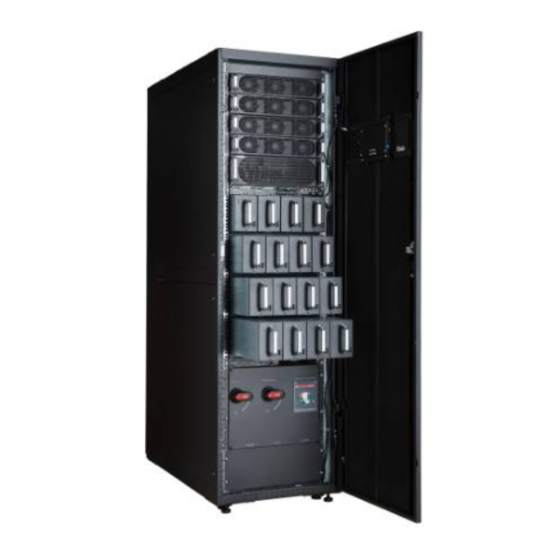
- Page 2 (CM) subrack cover (3) Filler panel (4) CM (5) Filler panels (6) Monitor display unit (5) Bypass module (6) Power modules (MDU) (7) MDU (7) Maintenance bypass switch Copyright © Huawei Technologies Co., Ltd. 2019. All rights reserved.
-
Page 3: Installing The Ups
Otherwise, personal injury or equipment damage may occur, and the resulting UPS faults are beyond the warranty scope. 4. This document describes how to install a single UPS. For details about how to install parallel systems, contact Huawei technical support. Installing the UPS Secured Installation 5. -
Page 4: Connecting Cables
Non-Secured Installation 7. Insert four M12x115 expansion bolts into the expansion bolt holes in the floor, and 1. Lower the four leveling feet at the bottom of the tighten the expansion bolts. cabinet by using a wrench until all the four castors at the bottom hang in the air and the leveling feet bear the whole cabinet weight. - Page 5 1. Remove the small covers of the cabinet top. 2. Remove the cover from the power distribution subrack. The cover can be opened only if the maintenance bypass switch is OFF. 3. Remove the copper bars between mains 4. Connect the ground cable to the UPS. input terminals and bypass input terminals.
- Page 6 5. Connect the mains input cables to mains input 6. Connect AC output power cables to the power distribution terminals 1L1, 1L2, and 1L3, output terminals N, U, V, and W on the UPS respectively. cabinet. Connect the bypass input cables to bypass input power distribution terminals 2L1, 2L2, and 2L3, respectively.
- Page 7 Connecting Cables to the UPS5000-E-320K-F320 Installing the Top Entry Cabinet 2. Level the feet of the top entry cabinet to make it in the same plane with the UPS. 1. Remove the right panel from the UPS and the 3. Remove the top cover of the top entry cabinet, front panel from the top entry cabinet, and put drill holes into the cover, remove the signal the panel and screws away.
- Page 8 Connecting Cables 1. remove the cover from the power distribution The following figure shows the reference cable subrack. routes for the cabinet. The basic rule is to route cables from inside out and from the bottom up. The cover can be opened only if the maintenance bypass switch is OFF.
- Page 9 4. Connect the mains input cables to mains 5. Connect AC output power cables to the input power distribution terminals 1L1, 1L2, output terminals N, U, V, and W on the UPS cabinet. and 1L3, respectively. Connect the bypass input cables to bypass input power distribution terminals 2L1, 2L2, and 2L3, respectively.
- Page 10 Connecting Cables to the UPS5000-E-320K-F320T Take the cable tray covers for the power cables and signal cables out of the cabinet, drill holes on the cable tray cover for the power cables, attach grommet strips on the hole edges for protecting cables, and reinstall the cable tray cover for the power cables.
- Page 11 4. Connect the mains input cables to mains 5. Connect AC output power cables to the input power distribution terminals 1L1, 1L2, output terminals N, U, V, and W on the UPS and 1L3, respectively. cabinet. Connect the bypass input cables to bypass input power distribution terminals 2L1, 2L2, M12x13.5 (4 PCS) and 2L3, respectively.
-
Page 12: Verifying The Installation
Verifying the Installation Item Acceptance Criteria Result □ Passed Cables are routed properly and meet Cable layout □ Failed engineering requirements. Input and output power cables and battery cables are securely connected and spring □ Passed Cable connections washers are flattened, prevent falling off and □... - Page 13 Close the input surge protection circuit breaker (if any). The UPS begins to work in normal mode and starts initialization. The LCD displays the Huawei logo and an initialization progress bar. NOTE If no input surge protection circuit breaker is configured, go to the next step. If the input surge protection circuit breaker is not closed, an alarm is generated and a message is displayed to prompt you to close it.
- Page 14 UPS. • A high or low charging power tends to shorten the battery lifespan, or even damages batteries. If you do not know how to confirm the battery capacity, contact Huawei technical support. • Number of cells indicates the number of 2 V DC cells connected to the UPS. The following table lists examples of setting battery parameters.
- Page 15 2. If no exception alarm is reported on the monitoring page after you specify settings on the Settings Wizard screen, perform subsequent steps. If exception alarms are reported on the monitoring page, clear all the alarms. 3. Check that the bypass input is normal and the system has transferred to bypass mode. You can confirm this by viewing the system running diagram on the LCD.
-
Page 16: Shutting Down The Ups
5. In the displayed dialog box, tap Yes to start the inverter. 6. Ensure that the UPS transfers to normal mode. View the system running diagram to check that the Bypass mode alarm disappears on the LCD. Check the UPS three-phase output voltage and frequency by viewing the AC Output on the LCD. - Page 17 Exporting Alarms to a USB Flash Drive HUAWEI TECHNOLOGIES CO., LTD. Huawei Industrial Base, Bantian, Longgang Shenzhen 518129 People's Republic of China www.huawei.com...
Need help?
Do you have a question about the UPS5000-E Series and is the answer not in the manual?
Questions and answers