Huawei UPS5000-E Series Quick Manual
Integrated ups, 208 v
Hide thumbs
Also See for UPS5000-E Series:
- User manual (300 pages) ,
- Quick manual (19 pages) ,
- User manual (203 pages)
Table of Contents
Advertisement
Quick Links
UPS5000-E-(20 kVA-80 kVA)
Quick Guide (Integrated UPS, 208 V)
Issue: 03
Part Number: 31507666
Date: 2019-06-28
1
Overview
UPS Model
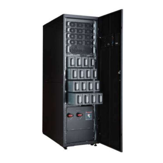
UPS5000-E-60K-LASBS
UPS5000-E-80K-LABBS
UPS5000-E-60K-LASBS
(1) AC transfer switch
(ATS)
(3) ATS handle
installation slot
(5) IT load 2 circuit
breaker
(7) UPS input circuit
breaker
(9) CM
(11) Power modules
(13) MDU
(15) UPS output
circuit breaker
Number of
Number of
Redundant
Modules
Modules
4
1
4
0
(2) Lighting circuit breaker
(4) Air conditioner circuit
breaker
(6) IT load 1 circuit breaker
(8) UPS maintenance
bypass switch
(10) Bypass module
(12) Power input indicator
(14) Power distribution
monitoring board
Copyright © Huawei Technologies Co., Ltd. 2019. All rights reserved.
Input
Switch
Weight
Type
ATS
480 kg
MCCB
UPS5000-E-80K-LABBS
(1) Power input
indicator0
(3) Lighting circuit
breaker
(5) IT load 2 circuit
breaker
(7) UPS input circuit
breaker
(9) Control Module
(CM)
(11) Power modules
(13) Power distribution
monitoring board
1
Dimensions (H x
W x D)
2000 mm x 600
mm x 1100 mm
(2) Input circuit
breaker
(4) Air conditioner
circuit breaker
(6) IT load 1 circuit
breaker
(8) UPS maintenance
bypass switch
(10) Bypass module
(12) Monitor display
unit (MDU)
(14) UPS output
circuit breaker
Advertisement
Table of Contents

Related Manuals for Huawei UPS5000-E Series


Summary of Contents for Huawei UPS5000-E Series
- Page 1 UPS5000-E-(20 kVA-80 kVA) Quick Guide (Integrated UPS, 208 V) Issue: 03 Part Number: 31507666 Date: 2019-06-28 Copyright © Huawei Technologies Co., Ltd. 2019. All rights reserved. Overview Number of Input Number of Dimensions (H x UPS Model Redundant Switch Weight...
-
Page 2: Installing The Ups
1. Before installation, read the UPS5000-E-(20 kVA-80 kVA) User Manual (Integrated UPS, 208 V) to get familiar with UPS information and safety precautions. 2. Use insulated tools during installation and operation. 3. Only engineers certified by the manufacturer or its agents are allowed to perform UPS installation and maintenance. - Page 3 Non-Secured Installation 1. Wrench an anchor bolt clockwise to elevate a cabinet, or wrench an anchor bolt anticlockwise to lower it. The cabinet feet can be adjusted within a range of 0–8 mm. 2. To prevent cabinet tilting and damage, adjust all the feet at the four corners instead of one foot. 3.
- Page 4 (Optional) Installing the Tail Frame Use eight M5 tapping screws to secure the tail 2. Use four M5 tapping screws to secure one frame accessories to the tail frame. as shown upper sealing plate to the tail frame, as shown in the following figure.
-
Page 5: Connecting Cables
After installing the cabinet rear door, adjust tail frame anchor bolts and ensure that anchor bolts touch the floor. Verify that ground cables are properly connected to the cabinet and cabinet rear door. (Optional) Combining Cabinets 2. Remove the cabinet connecting kits from the 1. - Page 6 1. Remove the five rodent-proof meshes and 2. Open the rear door, and remove the cable hole protection panels from the top of insulation panels at the rear of the the cabinet, as shown in the following figure. cabinet. 1. The basic rule for routing cables is: from inside out and from bottom up. 2.
- Page 7 Grounding for the safety ground of the UPS with the ATS input is the same as that of the UPS with the MCCB input. Grounding for the safety ground of the UPS with the ATS input is used as an example. Connect the ground cable to the floor ground bar or grounding busbar.
- Page 8 a. Connect output power cables to the b. Connect N cables and PE cables to the N bar customer terminal bars in the UPS cabinet. and PE bar on the left and right sides. (1) IT and air conditioner (2) Lighting output output power cables power cables •...
-
Page 9: Verifying The Installation
8. Route signal cables. Connect one end of the cable to the FE on the integrated UPS, and connect the other end to any POE port on the smart ETH gateway. Bind cables to the cabinet. The following figure shows cable routing inside the integrated UPS. Smart ETH gateway POE port After signal cable connection is complete,... - Page 10 Item Acceptance Criteria Result □ Passed Cables are properly connected according to Cable connections □ Failed wiring diagrams. Check that copper busbars are open- □ Passed Copper busbar short circuit circuited using a multimeteror an insulation □ Failed resistance tester. Input and output live wires and neutral wires are correctly connected.
- Page 11 Item Result □ Yes □ No All circuit breakers are OFF. Short circuit does not exist between phases of the AC input or between □ Yes □ No positive and negative battery terminals. Check this item by using a multimeter. Positive and negative battery terminals are connected correctly.
- Page 12 The automatic operation will be disabled after the handle is inserted into the switch panel. 5. Modify configurations of the 8D controller. You are not allowed to modify the ATS configurations if not authorized by Huawei engineers. a. Check whether the Power LED and Auto LED...
-
Page 13: Powering On And Starting The Ups
When the controller is in button mode, do not simultaneously press and hold down the I, II, and O buttons on the controller panel. Ensure that the interval between two commands is 5s at least. If another command is issued before the previous one is executed, the protection fuse (F1) under the electric operation mechanism may be blown. - Page 14 • A high or low charging power tends to shorten the battery lifespan, or even damages batteries. If you do not know how to confirm the battery capacity, contact Huawei technical support. • Number of cells indicates the number of 2 V DC cells connected to the UPS. Each cell is 2 V.
- Page 15 Battery Number of Number of Battery Number of Cells Battery Capacity Specifications Batteries Strings in a String 40 Ah/12 V 40 batteries Three battery strings 40 x 6 = 240 40 Ah + 40 Ah + 40 in series connected in parallel Ah = 120 Ah 100 Ah/12 V 32 batteries...
-
Page 16: Shutting Down The Ups
9. Turn on UPS output circuit breaker Q3 to supply power to loads. Shutting Down the UPS After the inverter is shut down, the system transfers to the bypass mode if the system bypass operates properly or provides no output for loads if the system bypass becomes faulty. Before you shut down the UPS, ensure that the loads are disconnected to meet any power failure conditions. - Page 17 Exporting Alarms to a USB Flash Drive Appendix System Configuration Attributes and Values Item Value Description Rated 208 V/120 V; 220 V/127 V; 230 V/132 V The default value is 208 V/120 V. Set the operating parameter based on site requirements. voltage Rated 50 Hz;...
- Page 18 System Configuration Attributes and Values Item Value Description –30% to –5% The step increase is ±1%. The Voltage Volt Threshold default settings are –10% for LN1 Thresholds Min LN1 –30% to –5% Volt Threshold and LN2. Set the parameter Min LN2 based on site requirements.
- Page 19 Setting BSC Mode 1. Set the master BSC system. On the main menu of the LCDs of the UPS, choose System Info > Settings. Tap Advanced Param. on the Settings screen. On the displayed screen, set BSC mode to BSC master mode. 2.
- Page 20 Scan here for technical support (carrier): Huawei App Store Scan here for more documents: Support-E Support WeChat You can also log in to Huawei technical support website: http://support.huawei.com/enterprise http://support.huawei.com Huawei Technologies Co., Ltd. Huawei Industrial Base, Bantian, Longgang Shenzhen 518129 People's Republic of China...
Need help?
Do you have a question about the UPS5000-E Series and is the answer not in the manual?
Questions and answers