Table of Contents
Advertisement
Quick Links
ICSTT-RM280N-EN-P (PD-T8451)
Trusted TMR 24 Vdc Digital Output Module – 40
Channel
Product Overview
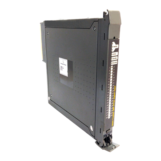
The Trusted® TMR 24 Vdc Digital Output Module interfaces to 40 field devices. Triplicated
diagnostic tests are performed throughout the Module including measurements for current, and
voltage on each portion of the voted output channel. Tests are also performed for stuck on and
stuck off failures. Fault tolerance is achieved through a Triple Modular Redundant (TMR)
architecture within the Module for each of the 40 output channels.
Automatic line monitoring of the field device is provided. This feature enables the Module to detect
both open and short circuit failures in field wiring and load devices.
The Module provides on-board Sequence of Events (SOE) reporting with a resolution of 1 ms. An
output change of state triggers an SOE entry. Output states are automatically determined by
voltage and current measurements on-board the Module.
This Module is not approved for direct connection to hazardous areas and should be used in
conjunction with Intrinsic Safety Barrier devices.
Features
• 40 Triple Modular Redundant (TMR) output points per Module.
• Comprehensive, automatic diagnostics and self-test.
• Automatic line monitoring per point to detect open circuit and short circuit field wiring and
load faults.
• 2500 V impulse withstand opto/galvanic isolation barrier.
• Automatic over-current protection (per channel), no external fuses required.
• On-board Sequence of Events (SOE) reporting with 1 ms resolution.
• Module can be hot-replaced on-line using dedicated Companion (adjacent) Slot or SmartSlot
(one spare slot for many Modules) configurations.
Rockwell Automation Publication ICSTT-RM280N-EN-P
Issue 14
Trusted
Advertisement
Table of Contents

Related Manuals for Rockwell Automation ICSTT-RM280N-EN-P


Summary of Contents for Rockwell Automation ICSTT-RM280N-EN-P
- Page 1 • Automatic over-current protection (per channel), no external fuses required. • On-board Sequence of Events (SOE) reporting with 1 ms resolution. • Module can be hot-replaced on-line using dedicated Companion (adjacent) Slot or SmartSlot (one spare slot for many Modules) configurations. Rockwell Automation Publication ICSTT-RM280N-EN-P Issue 14...
- Page 2 • Front Panel Module status LEDs indicate Module health and operational mode (Active, Standby, Educated). • TϋV Certified IEC 61508 SIL 3. • Outputs are powered in isolated groups of eight. Each such group is a Power Group (PG). Rockwell Automation Publication ICSTT-RM280N-EN-P Issue 14...
- Page 3 PREFACE PREFACE In no event will Rockwell Automation be responsible or liable for indirect or consequential damages resulting from the use or application of this equipment. The examples given in this manual are included solely for illustrative purposes. Because of the many variables and requirements related to any particular installation, Rockwell Automation does not assume responsibility or reliability for actual use based on the examples and diagrams.
- Page 4 Your comments help us to write better user documentation. If you discover an error, or have a suggestion on how to make this publication better, send your comment to our technical support group at http://rockwellautomation.custhelp.com Issue 14 Rockwell Automation Publication ICSTT-RM280N-EN-P...
- Page 5 IMPORTANT Identifies information that is critical for successful application and understanding of the product. NOTE Provides key information about the product or service. Tips give helpful information about using or setting up the equipment. Rockwell Automation Publication ICSTT-RM280N-EN-P Issue 14...
- Page 6 CAUTION: The module PCBs contain static sensitive components. Static handling precautions must be observed. DO NOT touch exposed connector pins or attempt to dismantle a module. Issue 14 Rockwell Automation Publication ICSTT-RM280N-EN-P...
- Page 7 Jan 19 Updated Specifications section and main text to a more consistent format. Updated Front Panel section to updated product design. Updated to display Rockwell Automation publication numbers. Added trademarks statement. Rockwell Automation Publication ICSTT-RM280N-EN-P Issue 14...
- Page 8 PREFACE Trusted TMR 24Vdc Digital Output Module – 40 Channel Page intentionally left blank Issue 14 Rockwell Automation Publication ICSTT-RM280N-EN-P...
-
Page 9: Table Of Contents
Rack 8: INFO ........................22 3.3. Sequence of Events Configuration ................... 24 3.4. System.INI File Configuration ....................24 Operation ......................25 4.1. Front Panel ..........................25 4.2. Module Status LEDs........................26 4.3. I/O Status Indicators ........................ 27 Rockwell Automation Publication ICSTT-RM280N-EN-P Issue 14... - Page 10 Field Wiring Faults ........................29 5.3. Module Faults .......................... 29 5.4. Companion Slot ........................30 5.5. SmartSlot ..........................30 5.6. Cold Start ..........................30 5.7. Transfer between Active and Standby Modules ..............31 Specifications ....................... 33 Issue 14 Rockwell Automation Publication ICSTT-RM280N-EN-P...
-
Page 11: Description
Figure 1 Module Architecture All High Integrity I/O Modules are made up of 4 sections: Host Interface Unit (HIU), the Field Interface Unit (FIU), the Field Termination Unit (FTU), and the Front Panel Unit (or FPU). Rockwell Automation Publication ICSTT-RM280N-EN-P Issue 14... -
Page 12: Field Termination Unit (Ftu)
FIUs, one per slice. For the TMR 24 Vdc Digital Output Module, the FIU contains one stage of the output switch structure, and sigma-delta (ΣΔ) output circuit for each of the 40 field outputs. Two additional ΣΔ circuits provide optional monitoring of the external field I/O supply voltage. Issue 14 Rockwell Automation Publication ICSTT-RM280N-EN-P... -
Page 13: Host Interface Unit (Hiu)
• Digital Signal Processing to perform local data reduction and self-diagnostics. • Local memory resources for storing Module operation, configuration, and field I/O data. • On-board housekeeping, which monitors reference voltages, current consumption and board temperature. Rockwell Automation Publication ICSTT-RM280N-EN-P Issue 14... -
Page 14: Front Panel Unit (Fpu)
Extensive diagnostics provide the automatic detection of Module faults. The TMR architecture of the Output Module and the diagnostics performed verify the validity of all critical circuits. Using the TMR architecture provides a Fault Tolerant method to withstand Issue 14 Rockwell Automation Publication ICSTT-RM280N-EN-P... -
Page 15: Sequence Of Events Characteristics
Sequence of Events (SOE) log. The user may configure each output to be included in the system SOE log. Full details of SOE are contained in Trusted Sequence of Events and Process Historian Package, publication ICSTT-RM243 (PD-T8013). Rockwell Automation Publication ICSTT-RM280N-EN-P Issue 14... -
Page 16: Output Switch Structure
Even if an entire slice fails, the surviving output circuits will carry the necessary control. Their “home” FIU. The home FIU, supplies an independent control signal for the “downstream” FIU FSS. For an un-faulted transistor. Issue 14 Rockwell Automation Publication ICSTT-RM280N-EN-P... -
Page 17: Switch Diagnostics
For the TMR switch configuration in the on state, only one fail safe switch at a time needs to be modulated, while the other two bear the load current. Rockwell Automation Publication ICSTT-RM280N-EN-P Issue 14... -
Page 18: Short Circuit Protection
If a slice fails, the watchdog on the HIU will time out and reset the slice, this will shutdown the FIU power supply and the associated GFSS control signal will also de-energise. Issue 14 Rockwell Automation Publication ICSTT-RM280N-EN-P... -
Page 19: Installation
I/O cables suitable for use with the Trusted TMR 24 Vdc Digital Output Module are detailed in the following Product Descriptions. • Trusted I/O Companion Slot Cables, publication ICSTT-RM311 (PD-TC200) • Trusted TMR I/O SmartSlot Slot Cables, publication ICSTT-RM313 (PD-TC500) Rockwell Automation Publication ICSTT-RM280N-EN-P Issue 14... -
Page 20: Termination
Chan 10 (+) Pwr Group 2 Rtn Pwr Group 2 (+) Pwr Group 2 Rtn Chan 15 (+) Pwr group 2 (+) Chan 11 (+) Chan 16 (+) Pwr Group 2 (+) Chan 12 (+) Issue 14 Rockwell Automation Publication ICSTT-RM280N-EN-P... - Page 21 Pwr Group 5 Rtn Pwr Group 5 (+) Pwr Group 5 Rtn Chan 39 (+) Pwr Group 5 (+) Chan 35 (+) Chan 40 (+) Pwr Group 5 (+) Chan 36 (+) Table 2 Field Connector Pin-out Rockwell Automation Publication ICSTT-RM280N-EN-P Issue 14...
-
Page 22: Trusted Module Polarisation/Keying
Fitted identified below) Release button Figure 5 Module Polarisation For Cables with Companion slot installations both keying strips must be polarised. For this Module (T8451) remove keying pins 1, 5 and 6. Issue 14 Rockwell Automation Publication ICSTT-RM280N-EN-P... -
Page 23: Application
Rack number: Rack I/O Board Description Data Type Direction No. of Channels OEM Parameters Field Output Status Boolean STATE Field Output State Integer Output voltage Integer Output current Integer LINE_FLT Line Fault Status Boolean Rockwell Automation Publication ICSTT-RM280N-EN-P Issue 14... -
Page 24: Rack 1: Do
This board provides the connection to the logical output control signal for each of the field outputs. Channel Description Field output channel 1 logical state Field output channel 2 logical state Field output channel 40 logical state Issue 14 Rockwell Automation Publication ICSTT-RM280N-EN-P... -
Page 25: Rack 2: State
Field fault (e.g. field leakage to 0 V or 24 V) Short circuit in field wiring or load Output energised (ON) Open circuit in field wiring or load Output de-energised (OFF) No field supply voltage Unused Table 7 Rack 2: STATE Output Description Rockwell Automation Publication ICSTT-RM280N-EN-P Issue 14... -
Page 26: Rack 3: Ai
IEC 61131 TOOLSET conversion tables. To scale the value arithmetically simply divide the returned ‘integer’ by 1000 to return the current as either a REAL or INTEGER as required. Issue 14 Rockwell Automation Publication ICSTT-RM280N-EN-P... -
Page 27: Rack 5: Line_Flt
Each of the words reports the discrepancy status of 16 output channels. The corresponding bit within the word is set to ‘1’ when a discrepancy condition is detected on that output channel’s output state (Rack 2). Rockwell Automation Publication ICSTT-RM280N-EN-P Issue 14... -
Page 28: Rack 7: Hkeeping
Front Panel Load Current -32768 32767 SmartSlot Link Voltage -32768 32767 FIU Output Group 1 Field Supply Voltage -32768 32767 FIU Board Temperature, Output Group 1 -32768 32767 (Note: Temperature, °C = input value / 256) Issue 14 Rockwell Automation Publication ICSTT-RM280N-EN-P... - Page 29 Table 12 Rack 7: Housekeeping Descriptions Each input within the housekeeping rack is reported as an integer. In general, the application engineer will not normally require these inputs. They are provided to aid fault Rockwell Automation Publication ICSTT-RM280N-EN-P Issue 14...
-
Page 30: Rack 8: Info
Module is healthy. The Active and Standby Module Mode is an integer indicating the current operating mode of the associated Module. The value indicates the current internal operating mode of the Module. Issue 14 Rockwell Automation Publication ICSTT-RM280N-EN-P... - Page 31 The ‘Active Module is simulated’ channel is set to non-zero if the Active Module is being simulated, this will only be set if the Module is not present or the simulation enable has been set within the Module’s configuration in the System.INI file. Rockwell Automation Publication ICSTT-RM280N-EN-P Issue 14...
-
Page 32: Sequence Of Events Configuration
Module definition in the System Configuration Manager is not required. In order for short circuit detection to function while outputs are de-energised, a short circuit detection template is required. Issue 14 Rockwell Automation Publication ICSTT-RM280N-EN-P... -
Page 33: Operation
The ejector levers are normally latched closed when the Module is firmly seated into the Controller or Expander Chassis. Module Latch Module Status Indicators Channel Status Indicators Module Latch Figure 6 Module Front Panel Rockwell Automation Publication ICSTT-RM280N-EN-P Issue 14... -
Page 34: Module Status Leds
Module is in the fatal state if the Standby LED is also flashing. Standby Module is not in the Standby state. Green Module is in the Standby state. Red – flashing Module is in the fatal state. The Active LED will also be flashing red. Issue 14 Rockwell Automation Publication ICSTT-RM280N-EN-P... -
Page 35: I/O Status Indicators
Table 17 I/O Status LEDs Note: The LEDs indicating channel status may be configured to suit user requirements by implementing the procedure for configuring the System.INI file detailed in Trusted Toolset Suite, publication ICSTT-RM249 (PD- T8082). Rockwell Automation Publication ICSTT-RM280N-EN-P Issue 14... - Page 36 4. Operation Trusted TMR 24Vdc Digital Output Module – 40 Channel Page intentionally left blank Issue 14 Rockwell Automation Publication ICSTT-RM280N-EN-P...
-
Page 37: Fault Finding And Maintenance
Module replacement activities depend on the type of spare Module configuration chosen when the system was configured and installed. The Module may be configured with a Dedicated Standby Slot or with a SmartSlot for a spare replacement Module. Rockwell Automation Publication ICSTT-RM280N-EN-P Issue 14... -
Page 38: Companion Slot
The I/O functions provided by this Module will have been lost if a hot swap partner has not taken over control. The Module can only be restarted by removing it from its slot and re-inserting it. Issue 14 Rockwell Automation Publication ICSTT-RM280N-EN-P... -
Page 39: Transfer Between Active And Standby Modules
Once it becomes aware of the fault, the TMR Processor will attempt an Active/Standby changeover. • An Active/Standby changeover starts with the TMR Processor checking to see if a Standby I/O Module is installed. If no Standby I/O Module is available, the TMR Rockwell Automation Publication ICSTT-RM280N-EN-P Issue 14... - Page 40 Module. This can be accomplished by opening the Module Removal switches on the currently Active Module and pressing the reset pushbutton on the TMR Processor. This will force the changeover to proceed even if the new Active Module is not fault free. Issue 14 Rockwell Automation Publication ICSTT-RM280N-EN-P...
-
Page 41: Specifications
250 V Basic (fault) [Type tested at 2436 Vdc for 60 s]. Channel to Channel (within Power Group) None Fusing Not user serviceable Number of Outputs Number of Power Groups Each Power Group comprises 8 channels Rockwell Automation Publication ICSTT-RM280N-EN-P Issue 14... - Page 42 Note 2) 250 Vrms Mains circuit, OVC II up to 300V. Exposure to voltages at these levels shall be temporally constrained consistent with the system MTTR. Note 3) Tolerance is ±5 mA up to 1.8 A, thereafter is ±5 %. Issue 14 Rockwell Automation Publication ICSTT-RM280N-EN-P...
Need help?
Do you have a question about the ICSTT-RM280N-EN-P and is the answer not in the manual?
Questions and answers