
Related Manuals for Rockwell Automation Series C


Summary of Contents for Rockwell Automation Series C
-
Page 1: Table Of Contents
Installation Instructions POINT I/O 120V AC Input Module Catalog numbers 1734-IA2, 1734-IA4, Series C Table of Contents Topic Page Important User Information Environment and Enclosure Preventing Electrostatic Discharge North American Hazardous Location Approval European Hazardous Location Approval Before You Begin... -
Page 2: Important User Information
In no event will Rockwell Automation, Inc. be responsible or liable for indirect or consequential damages resulting from the use or application of this equipment. -
Page 3: Environment And Enclosure
POINT I/O 120V AC Input Module Environment and Enclosure ATTENTION: This equipment is intended for use in a Pollution Degree 2 industrial environment, in overvoltage Category II applications (as defined in IEC publication 60664-1), at altitudes up to 2000 meters (6562 ft) without derating. This equipment is considered Group 1, Class A industrial equipment according to IEC/CISPR Publication 11. -
Page 4: North American Hazardous Location Approval
4 POINT I/O 120V AC Input Module North American Hazardous Location Approval The following information applies when Informations sur l’utilisation de cet operating this equipment in hazardous équipement en environnements dangereux: locations: Products marked "CL I, DIV 2, GP A, B, C, D" are suitable for Les produits marqués "CL I, DIV 2, GP A, B, C, D"... -
Page 5: European Hazardous Location Approval
WARNING: This equipment shall be used within its specified ratings defined by Rockwell Automation. WARNING: Provision shall be made to prevent the rated voltage from being exceeded by transient disturbances of more than 140% of the rated voltage when applied in Zone 2 environments. -
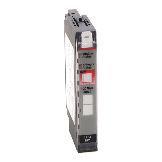
Page 6: Before You Begin
You can use these POINT I/O™ 120V AC Input modules with DeviceNet and PROFIBUS adapters. If you are using RSLogix 5000 software, version 11 or higher, you can also use the Series C modules with ControlNet and Ethernet adapters. Use this diagram to identify the external features of the module. - Page 7 POINT I/O 120V AC Input Module 45712 Description Description Module locking mechanism Interlocking side pieces Slide-in writable label Mechanical keying (orange) Insertable I/O module DIN rail locking screw (orange) Handle Module wiring diagram One-piece terminal base with screw or spring clamp – 1734-TOP, 1734-TOPS Publication 1734-IN010E-EN-E - August 2016...
-
Page 8: Install The Mounting Base
8 POINT I/O 120V AC Input Module Install the Mounting Base To install the mounting base on the DIN rail (Allen-Bradley part number 199-DR1; 46277-3; EN50022), proceed as follows: ATTENTION: This product is grounded through the DIN rail to chassis ground. Use zinc plated yellow-chromate steel DIN rail to assure proper grounding. -
Page 9: Install The Module
POINT I/O 120V AC Input Module Install the Module The module can be installed before or after base installation. Make sure that the mounting base is correctly keyed before installing the module into the mounting base. In addition, make sure the mounting base locking screw is positioned horizontal referenced to the base. WARNING: When you insert or remove the module while backplane power is on, an electrical arc can occur. - Page 10 10 POINT I/O 120V AC Input Module 1734-TOP base Make sure the DIN-rail locking screw is in the horizontal position. Turn the keyswitch to align the number with the notch. Notch position 1 is shown here. 45697 1. Using a bladed screwdriver, rotate the keyswitch on the mounting base clockwise until the number required for the type of module being installed aligns with the notch in the base.
-
Page 11: Install The Removable Terminal Block
POINT I/O 120V AC Input Module Install the Removable Terminal Block A Removable Terminal Block (RTB) is supplied with your wiring base assembly. To remove, pull up on the RTB handle. This allows the mounting base to be removed and replaced as necessary without removing any of the wiring. - Page 12 12 POINT I/O 120V AC Input Module WARNING: For 1734-RTBS and 1734-RTB3S, to latch and un-latch the wire, insert a bladed screwdriver (catalog number 1492-N90 – 3 mm diameter blade) into the opening at approximately 73° (blade surface is parallel with top surface of the opening) and push up gently.
-
Page 13: Remove A Mounting Base
POINT I/O 120V AC Input Module Remove a Mounting Base To remove a mounting base, you must remove any installed module, and the module installed in the base to the right. Remove the Removable Terminal Block, if wired. 1. Unlatch the RTB handle on the I/O module. 2. -
Page 14: Wire The Module
14 POINT I/O 120V AC Input Module Wire the Module 1734-IA2 1734-IA4 Module status Module status Module Module Status Status Network status Network status Network Network Status Status NODE: NODE: 120VAC 120VAC Input Input Status of Input 0 Status of Input 0 Status of Input 1 Status of Input 1 Status of Input 2... - Page 15 POINT I/O 120V AC Input Module 1734-IA2 Ch 0 Ch 1 Prox Prox Two-wire Three-wire L2/N L2/N Ch 0 = Channel 0 input L2/N = 120V AC neutral Ch 1 = Channel 1 input L1 = 120V AC NC = No connection Channel Input terminal Return...
- Page 16 16 POINT I/O 120V AC Input Module 1734-IA4 Ch 0 Ch 1 Ch 2 Ch 3 Prox Prox Prox Prox L2/N Ch 0 = Channel 0 input L2/N Ch 3 = Channel 3 input Ch 1 = Channel 1 input L2/N = 120V AC neutral Ch 2 = Channel 2 input L1 = 120V AC...
-
Page 17: Communicate With Your Module
POINT I/O 120V AC Input Module Communicate with Your Module I/O messages are sent to (consumed) and received from (produced) the POINT I/O modules. These messages are mapped onto the processor’s memory. The POINT I/O output module produces 1 Byte of input data (scanner Tx) (state). It does not consume data (scanner Rx). -
Page 18: Interpret Status Indicators
18 POINT I/O 120V AC Input Module Interpret Status Indicators Refer to the following diagram and table for information on how to interpret the status indicators. 1734-IA2 1734-IA4 Module status Module status Network status Network status Status of Input 0 Status of Input 0 Status of Input 1 Status of Input 1... - Page 19 POINT I/O 120V AC Input Module Indicator Status for Modules Status Description Recommended Action Network status Off Device is not online: Apply power to device, wait for - Device has not completed dup_MAC-id test to complete, dup_MAC-id test. and correct as needed. - Device not powered –...
-
Page 20: Specifications
20 POINT I/O 120V AC Input Module Specifications POINT I/O 120V AC Input Module – 1734-IA2, 1734-IA4, Series C Attribute Value Number of inputs 1734-IA2 – 2 (1 group of 2) nonisolated, sinking 1734-IA4 – 4 (1 group of 4) nonisolated, sinking... - Page 21 POINT I/O 120V AC Input Module General Specifications Attribute Value Weight, approx. 30.9 g (1.09 oz) North American temp code IEC temp code Enclosure type rating None (open-style) Delay time 20 ms hardware filter plus 1...65 ms digital filter programmable in Off to On and On to Off increments of 1 ms Keyswitch position...
- Page 22 22 POINT I/O 120V AC Input Module Environmental Specifications Attribute Value ESD Immunity IEC 61000-4-2: 6 kV contact discharges 8 kV air discharges Radiated RF Immunity IEC 61000-4-3: 10V/m with 1 kHz sine-wave 80% AM from 80...2000 MHz 10V/m with 200 Hz 50% Pulse 100% AM @ 900 MHz 10V/m with 200 Hz 50% Pulse 100% AM @ 1890 MHz 3V/m with 1 kHz sine-wave 80% AM from 2000...2700 MHz EFT/B Immunity...
- Page 23 POINT I/O 120V AC Input Module Certifications Certification (when Value product is marked) Russian Customs Union TR CU 020/2011 EMC Technical Regulation Australian Radiocommunications Act, compliant with: AS/NZS CISPR 11; Industrial Emissions. Korean Registration of Broadcasting and Communications Equipment, compliant with: Article 58-2 of Radio Waves Act, Clause 3 See the Product Certification link at http://www.rockwellautomation.com/products/certification/...
- Page 24 Rockwell Automation representative. New Product Satisfaction Return Rockwell Automation tests all of its products to ensure that they are fully operational when shipped from the manufacturing facility. However, if your product is not functioning and needs to be returned, follow these procedures.
Need help?
Do you have a question about the Series C and is the answer not in the manual?
Questions and answers