Table of Contents
Advertisement
Quick Links
Installation Instructions
Compact I/O Modules
AC Digital Modules 1769-IA8I, 1769-IA16, 1769-IM12, 1769-OA8, 1769-OA16
DC Digital Modules 1769-IG16, 1769-IQ16, 1769-IQ16F, 1769-IQ32, 1769-IQ32T, 1769-IQ6XOW4,
1769-OB8, 1769-OB16, 1769-OB16P, 1769-OB32, 1769-OB32T, 1769-OG16, 1769-OV16, 1769-OV32T
Contact Modules 1769-OW8, 1769-OW8I, 1769-OW16
Analog Modules 1769-IF4, 1769-IF4I, 1769-IF4XOF2, 1769-IF4FXOF2F, 1769-IF8, 1769-IF16C,
1769-IF16V, 1769-IR6, 1769-IT6, 1769-OF2, 1769-OF4, 1769-OF4CI, 1769-OF4VI, 1769-OF8C, 1769-OF8V
Speciality Modules 1769-ARM, 1769-ASCII, 1769-BOOLEAN, 1769-HSC
Advertisement
Table of Contents

Related Manuals for Rockwell Automation Allen-Bradley 1769-IA16


Summary of Contents for Rockwell Automation Allen-Bradley 1769-IA16
- Page 1 Installation Instructions Compact I/O Modules AC Digital Modules 1769-IA8I, 1769-IA16, 1769-IM12, 1769-OA8, 1769-OA16 DC Digital Modules 1769-IG16, 1769-IQ16, 1769-IQ16F, 1769-IQ32, 1769-IQ32T, 1769-IQ6XOW4, 1769-OB8, 1769-OB16, 1769-OB16P, 1769-OB32, 1769-OB32T, 1769-OG16, 1769-OV16, 1769-OV32T Contact Modules 1769-OW8, 1769-OW8I, 1769-OW16 Analog Modules 1769-IF4, 1769-IF4I, 1769-IF4XOF2, 1769-IF4FXOF2F, 1769-IF8, 1769-IF16C, 1769-IF16V, 1769-IR6, 1769-IT6, 1769-OF2, 1769-OF4, 1769-OF4CI, 1769-OF4VI, 1769-OF8C, 1769-OF8V Speciality Modules 1769-ARM, 1769-ASCII, 1769-BOOLEAN, 1769-HSC...
- Page 2 Identifies information that is critical for successful application and understanding of the product. IMPORTANT Allen-Bradley, Compact I/O, Rockwell Automation, Rockwell Software, RSLogix 500, RSLogix 5000, RSNetWorx for DeviceNet, and TechConnect are trademarks of Rockwell Automation, Inc. Trademarks not belonging to Rockwell Automation are property of their respective companies.
-
Page 3: Table Of Contents
1769-OB32T ........... . 39 Rockwell Automation Publication 1769-IN088A-EN-P - February 2011... - Page 4 Output Data File ..........81 Rockwell Automation Publication 1769-IN088A-EN-P - February 2011...
- Page 5 Output Data File ..........117 Rockwell Automation Publication 1769-IN088A-EN-P - February 2011...
- Page 6 Output Module’s Input Data File ......165 Rockwell Automation Publication 1769-IN088A-EN-P - February 2011...
- Page 7 ..............197 Rockwell Automation Publication 1769-IN088A-EN-P - February 2011...
- Page 8 Table of Contents Notes: Rockwell Automation Publication 1769-IN088A-EN-P - February 2011...
-
Page 9: Additional Resources
1769-UM020 troubleshoot the 1769 analog I/O module. You can view or download publications at http://www.rockwellautomation.com/ literature/. To order paper copies of technical documentation, contact your local Rockwell Automation distributor or sales representative. Rockwell Automation Publication 1769-IN088A-EN-P - February 2011... - Page 10 Preface Notes: Rockwell Automation Publication 1769-IN088A-EN-P - February 2011...
-
Page 11: Before You Begin
Write-on label (user ID tag) Movable bus connector with female pins Removable terminal block (RTB) with finger-safe cover Stationary bus connector with male pins RTB upper retaining screw Nameplate label RTB lower retaining screw Rockwell Automation Publication 1769-IN088A-EN-P - February 2011... - Page 12 Sending an erroneous signal to your system’s field devices causing unintended machine motion Causing an explosion in a hazardous environment Electrical arcing causes excessive wear to contacts on both the module and its mating connector. Worn contacts may create electrical resistance. Rockwell Automation Publication 1769-IN088A-EN-P - February 2011...
-
Page 13: Hazardous Location Considerations
Ce produit doit être installé dans une armoire. Install Summary Follow these steps to install the module. System Assembly. Ground the Module. Wire the Module. This publication describes these steps in detail. Rockwell Automation Publication 1769-IN088A-EN-P - February 2011... -
Page 14: System Assembly
7. Make sure the lever is locked firmly in place. ATTENTION: When attaching I/O modules, it is very important that the bus connectors are securely locked together to make a proper electrical connection. Rockwell Automation Publication 1769-IN088A-EN-P - February 2011... -
Page 15: Minimum Spacing
Compact I/O modules Bottom End cap Host controller Panel Mounting Mount the module to a panel by using two screws per module. Use M4 or #8 panhead screws. Mounting screws are required on every module. Rockwell Automation Publication 1769-IN088A-EN-P - February 2011... -
Page 16: Din Rail Mounting
Before mounting the module on a DIN rail, close the DIN rail latches. Press the DIN rail mounting area of the module against the DIN rail. The latches will momentarily open and lock into place. Rockwell Automation Publication 1769-IN088A-EN-P - February 2011... -
Page 17: Replace A Module
Additional grounding connections from the module’s mounting tabs or DIN rail are not required unless the mounting surface cannot be grounded. Refer to the Industrial Automation Wiring and Grounding Guidelines, publication 1770-4.1, for additional information. Rockwell Automation Publication 1769-IN088A-EN-P - February 2011... -
Page 18: Wire The Module
A removable, write-on label is provided with the module. Remove the label from the door, mark the identification of each terminal with permanent ink, and slide the label back into the door. Your markings (ID tag) will be visible when the module door is closed. Rockwell Automation Publication 1769-IN088A-EN-P - February 2011... -
Page 19: Remove The Terminal Block
If you wire the terminal block with the finger-safe cover removed, you will not be able to put it back on the terminal block because the wires will be in the way. Rockwell Automation Publication 1769-IN088A-EN-P - February 2011... -
Page 20: Wire Size And Terminal Screw Torque
Retaining Screw Torque Torque Solid Cu-90 °C (194 °F) #14…#22 AWG 0.68 N•m (6 lb•in) 0.46 N•m (4.1 lb•in) Stranded Cu-90 °C (194 °F) #16…#22 AWG 0.68 N•m (6 lb•in) 0.46 N•m (4.1 lb•in) Rockwell Automation Publication 1769-IN088A-EN-P - February 2011... -
Page 21: 1769-Ia8I
IN 2 IN 3 IN 4 IN 5 IN 6 100/120V AC IN 7 IN 8 IN 9 IN 10 IN 11 IN 12 IN 13 IN 14 IN 15 Commons are connected internally. Rockwell Automation Publication 1769-IN088A-EN-P - February 2011... -
Page 22: 1769-If4
ANLG Com V in 3 + – V/I in 3 - I in 3 + ANLG Com +24V DC Two-wire Signal DC NEUT Current Sensor/ Transmitter – Supply External 24V DC Power – Supply Rockwell Automation Publication 1769-IN088A-EN-P - February 2011... -
Page 23: 1769-If4I
Voltage Ground Signal 1769-IF4I Mixed Transmitter Inputs Ch0+ Sensor/ Transmitter Ch0_iRtn Current Supply Signal Ch0- Ch1+ Ch1_iRtn Voltage Ch1- Ground Signal Ch2+ Voltage Ch2_iRtn Ground Signal Ch2- Ch3+ Ch3_iRtn Ch3- Differential Voltage Signal Rockwell Automation Publication 1769-IN088A-EN-P - February 2011... -
Page 24: 1769-If4Xof2
Signal V out 1+ Two-wire I out 0+ I out 1 + Current V out 1+ I out 1 + Sensor/ Transmitter The sensor power supply must be rated Class 2. – Supply Rockwell Automation Publication 1769-IN088A-EN-P - February 2011... -
Page 25: 1769-If4Fxof2F
Signal Two-wire V out 1+ I out 0+ I out 1 + Current V out 1+ I out 1 + Sensor/ Transmitter The sensor power supply must be rated Class 2. – Supply Rockwell Automation Publication 1769-IN088A-EN-P - February 2011... - Page 26 V/I in 2- V in 3+ I in 3+ Voltage V/I in 3- ANLG Com ANLG Com Earth Ground V out 0+ I out 0+ V out 1+ Current I out 1 + Earth Ground Rockwell Automation Publication 1769-IN088A-EN-P - February 2011...
-
Page 27: 1769-If8
I in 2 + Voltage AN LG C om Ground Signal V in 3 + V/I in 3 - I in 3 + AN LG C om Wiring for channels 4…7 are identical. Rockwell Automation Publication 1769-IN088A-EN-P - February 2011... -
Page 28: 1769-If16C
10 M IN4+ 20 K Current IN5+ Gain IN6+ IN7+ Ground 0.1 μF Signal IN8+ 20 K IN9+ IN10+ IN11+ IN12+ IN13+ IN14+ IN15+ The sensor power supply must be rated Class 2. Rockwell Automation Publication 1769-IN088A-EN-P - February 2011... -
Page 29: 1769-If16V
DC power cable and I/O cables should not exceed 10 m (30 ft). The capacitors shown above must be 0.01 F and rated for 2000V min. µ User power supply must be rated Class 2 with a 5V DC range of 4.5…5.5V DC. Rockwell Automation Publication 1769-IN088A-EN-P - February 2011... -
Page 30: 1769-Im12
+DC (sinking) COM 1 -DC (sinking) -DC (sourcing) +DC (sourcing) IN 9 IN 8 IN 11 24V DC IN 10 IN 13 IN 12 IN 15 IN 14 -DC (sinking) COM 2 +DC (sourcing) Rockwell Automation Publication 1769-IN088A-EN-P - February 2011... -
Page 31: 1769-Iq16F
IN 26 IN 13 IN 29 IN 12 IN 28 IN 15 IN 31 IN 14 IN 30 COM 2 COM 4 – DC (Sinking) – DC (Sinking) + DC (Sourcing) + DC (Sourcing) Rockwell Automation Publication 1769-IN088A-EN-P - February 2011... -
Page 32: 1769-Iq32T
Chapter 2 Module Wiring 1769-IQ32T Compact 24V DC sink/source, terminated input module 1769-IQ32T Rockwell Automation Publication 1769-IN088A-EN-P - February 2011... -
Page 33: 1769-Iq6Xow4
0. 1 μF DC COM +DC (sinking) -DC (sourcing) IN 0 IN 1 Simplified Output Circuit Diagram 24V DC IN 2 IN 3 IN 4 +24V -DC (sinking) IN 5 +DC (sourcing) VAC- VDC Rockwell Automation Publication 1769-IN088A-EN-P - February 2011... -
Page 34: 1769-Ir6
Four-wire RTD Configuration Cable Shield (to Ground) RTD EXC RTD EXC EXC 3 Sense Sense SENSE 3 Return Return RTN 3 EXC 4 Belden 83503 or 9533 Shielded Cable Leave one sensor wire open. Rockwell Automation Publication 1769-IN088A-EN-P - February 2011... - Page 35 Run RTD EXC and sense wires from the module to Cable Shield (to Ground) potentiometer terminal and tie terminal to one point. RTD EXC Potentiometer EXC 3 Sense SENSE 3 Return RTN 3 Belden 83503 or 9533 Shielded Cable Rockwell Automation Publication 1769-IN088A-EN-P - February 2011...
-
Page 36: 1769-It6
Compact 100/240V AC solid state output module 1769-OA8 Simplified Output Circuit Diagram VAC 1 OUT0 OUT1 100 to 240V AC OUT2 OUT3 470V VAC 2 0.015μF OUT5 OUT4 OUT7 OUT6 100 to 240V AC Rockwell Automation Publication 1769-IN088A-EN-P - February 2011... -
Page 37: 1769-Oa16
Simplified Output Circuit Diagram +VDC 1 Logic Side User Side OUT 0 OUT 1 OUT 2 OUT 3 DC COM DC - +VDC 2 OUT 4 OUT 5 ASIC OUT 6 OUT 7 DC COM Rockwell Automation Publication 1769-IN088A-EN-P - February 2011... -
Page 38: 1769-Ob16
OUT 5 OUT 6 100pF OUT 7 24V DC OUT 8 OUT 9 OUT 10 OUT 11 OUT 12 OUT 13 OUT 14 OUT 15 DC COM DC COM Protection circuit is not shown. Rockwell Automation Publication 1769-IN088A-EN-P - February 2011... -
Page 39: 1769-Ob32
ASIC 1769-OB32T Compact solid state 24V DC source, terminated output module 1769-OB32T Simplified Output Circuit Diagram +VDC 1 +VDC 2 +VDC 1 +VDC 2 Logic Side User Side V DC V DC ASIC Rockwell Automation Publication 1769-IN088A-EN-P - February 2011... -
Page 40: 1769-Of2
Converter ANLG Com Current ANLG Com Earth Ground V out 0+ Output I out 0+ +15V V out 1+ Current Load Isolated I out 1 + DC to DC Earth Ground Converter -15V Rockwell Automation Publication 1769-IN088A-EN-P - February 2011... -
Page 41: 1769-Of4Ci
Module Wiring Chapter 2 1769-OF4CI Compact current output, individually isolated analog module 1769-OF4CI Current Earth Ground 1769-OF4VI Compact voltage output, individually isolated analog module 1769-OF4VI Voltage Earth Ground Rockwell Automation Publication 1769-IN088A-EN-P - February 2011... -
Page 42: 1769-Of8C
DC NEUT +24V DC The external power supply must be rated Class 2, with a 24V DC range of 20.4…6.4V DC and 60 mA minimum. Series B and later modules support this option. Rockwell Automation Publication 1769-IN088A-EN-P - February 2011... -
Page 43: 1769-Of8V
DC NEUT +24V DC The external power supply must be rated Class 2, with a 24V DC range of 20.4…6.4V DC and 60 mA minimum. Series B and later modules support this option. Rockwell Automation Publication 1769-IN088A-EN-P - February 2011... -
Page 44: 1769-Og16
0. 1 μF OUT 7 OUT 8 24V DC (sink) 6. 8 K OUT 9 OUT 10 OUT 11 4. 7 K OUT 12 DC COM OUT 13 OUT 14 OUT 15 DC COM Rockwell Automation Publication 1769-IN088A-EN-P - February 2011... -
Page 45: 1769-Ov32T
VAC - VDC VAC-VDC L1 or +DC OUT 0 L2 or -DC OUT 1 OUT 2 OUT 3 VAC-VDC L1 or +DC OUT 5 L2 or -DC OUT 4 OUT 7 OUT 6 Rockwell Automation Publication 1769-IN088A-EN-P - February 2011... -
Page 46: 1769-Ow8I
OUT 10 OUT 13 OUT 12 OUT 15 OUT 14 L2 or -DC 1769-ARM The 1769-ARM module is an address reserve module for reserving I/O module slots. As a result, no wiring is required. Rockwell Automation Publication 1769-IN088A-EN-P - February 2011... -
Page 47: 1769-Ascii
ASCII TXD- RXD- RXD- TXD- RXD+ TXD+ TXD+ RXD+ RS-232 Wiring Module to Printer (hardware handshaking enabled, standard RS-485 Wiring printer adapter cable) ASCII DTE 9-pin 25-pin ASCII TRXD- TRXD- N.C. TRXD+ TRXD+ Rockwell Automation Publication 1769-IN088A-EN-P - February 2011... -
Page 48: 1769-Boolean
300 m (1000 ft). A1(+) A1(–) B1(+) Allen-Bradley B1(–) 845H Series Z1(+) differential Z1(–) encoder. Shield Shield/Housing Earth Connect only if housing is electronically Module Inputs isolated from the motor and ground. Rockwell Automation Publication 1769-IN088A-EN-P - February 2011... - Page 49 = 6.8 mA Power Supply Voltage Pull-up Resistor Value Max (R) 352 Ω 5V DC 1382 Ω 12V DC 3147 Ω 24V DC (1) Resistance values may change, depending upon your application. Rockwell Automation Publication 1769-IN088A-EN-P - February 2011...
- Page 50 5V DC 1382 Ω 12V DC 3147 Ω 24V DC (1) Resistance values may change, depending upon your application. The minimum resistor (R) value depends on the current sinking capability of the encoder. Rockwell Automation Publication 1769-IN088A-EN-P - February 2011...
- Page 51 Module Wiring Chapter 2 Output Wiring OUT DC +5/24V DC OUT 0 OUT 1 OUT 2 OUT 3 DC COM +5/24V DC Rockwell Automation Publication 1769-IN088A-EN-P - February 2011...
- Page 52 Chapter 2 Module Wiring Notes: Rockwell Automation Publication 1769-IN088A-EN-P - February 2011...
-
Page 53: I/O Memory Mapping
1769-OB16, Series B 1769-OB16P 1769-OB32 1769-OB32T 1769-OG16 1769-OV16 1769-OV32T Contact 1769-OW8 1769-OW8I 1769-OW16 Analog 1769-IF4 1769-IF4I 1769-IF4XOF2 1769-IF4FXOF2F 1769-IF8 1769-IF16C 1769-IF16V 1769-IR6 1769-IT6 1769-OF2 1769-OF4 1769-OF4CI 1769-OF4VI 1769-OF8C 1769-OF8V Specialty 1769-ARM 1769-ASCII 1769-BOOLEAN 1769-HSC Rockwell Automation Publication 1769-IN088A-EN-P - February 2011... -
Page 54: 1769-Ia8I
The following I/O memory mapping lets you configure the 1769-IA16 module. Input Data File For each input module, slot , word 0 in the input data file contains the current state of the field input points. Bit Position (1) r = read. Rockwell Automation Publication 1769-IN088A-EN-P - February 2011... -
Page 55: 1769-If4
1769-ADN DeviceNet adapter, also allow the bits to be altered as part of the control program using communication rungs. In that case, it is necessary to understand the bit arrangement. Refer to the Compact I/O Analog Modules User Manual, publication number 1769-UM002 for additional details. Rockwell Automation Publication 1769-IN088A-EN-P - February 2011... - Page 56 Raw/Proportional Format Data Engineering Units Scaled-for-PID Percent Range Spare Enable Channel Enabled Disabled (1) An attempt to write any nonvalid (spare) bit configuration into any selection field results in a module configuration error. Rockwell Automation Publication 1769-IN088A-EN-P - February 2011...
-
Page 57: 1769-If4I
20 mA range. O = Over-range flag bits for channels 0…3. When set, the input signal is over normal range or an open circuit condition exists. Open circuit detection applies to voltage input ranges only. Rockwell Automation Publication 1769-IN088A-EN-P - February 2011... -
Page 58: Output Data File
Inpt Dta Fm Reserved Inpt Tp/RngeSel Chl1 Chl1 10 S Process Alarm High Data Value Channel 1 11 S Process Alarm Low Data Value Channel 1 12 S Alarm Dead Band Value Channel 1 Rockwell Automation Publication 1769-IN088A-EN-P - February 2011... - Page 59 Inpt Tp/Rnge Sel Chlx = Input Type/Range Select. Inpt Filter Sel Chlx = Input Filter Select. Reserved = Allows for future expansion. ETS = Enable Time Stamp. (1) MicroLogix 1500 and CompactLogix L3x controllers do not support interrupts. Rockwell Automation Publication 1769-IN088A-EN-P - February 2011...
- Page 60 These bit settings 15…11 10 7…4 Input Range Select -10…+10V dc 0…5V dc 0…10V dc 4…20 mA 1…5V dc 0…20 mA Input Data Select Raw/Proportional Counts Engineering Units Scaled for PID Percent Range Rockwell Automation Publication 1769-IN088A-EN-P - February 2011...
-
Page 61: 1769-If4Xof2
However, the module continues to convert analog data to the maximum full-range value. When the over-range condition is cleared, the bits automatically reset (0). Rockwell Automation Publication 1769-IN088A-EN-P - February 2011... -
Page 62: Output Data File
If a MVM (Move with Mask) instruction is used with a mask of 7F80 (hexidecimal) to move data to the output words, writing to bits 0 through 6 and bit 15 can be avoided. Rockwell Automation Publication 1769-IN088A-EN-P - February 2011... -
Page 63: Configuration Data File
The enable bit remains set even when a channel is configured incorrectly. However, a configuration error for that channel is set. When this occurs, disable the channel, reconfigure the channel correctly, and then enable the channel. Rockwell Automation Publication 1769-IN088A-EN-P - February 2011... - Page 64 The module default is zero. PMx, FMx, PFEx, Channel x Program (Idle) Value and Channel x IMPORTANT Fault Value functions are not supported by all controllers. Refer to your controller’s user manual for details. Rockwell Automation Publication 1769-IN088A-EN-P - February 2011...
-
Page 65: 1769-If4Fxof2F
LI = Low Alarm flag bits for input channels 0…3. SO = General Status bit for output channels 0…1. OO = Over range flag bits for output channels 0…1. UO = Under range flag bits for output channels 0…1. Rockwell Automation Publication 1769-IN088A-EN-P - February 2011... -
Page 66: Output Data File
Bit Position Real Time Sample Value Reserved Reserved Reserved Input Filter Sel ChI0 Reserved Input Dta Fm Reserved Inpt Tp/Rnge Sel ChI0 ChI0 SGN Process Alarm High Data Value Channel 0 Rockwell Automation Publication 1769-IN088A-EN-P - February 2011... - Page 67 Reserved EHI ELI FM PM 0 Reserved Outpt Fm ChI1 Reserved Outpt Tp/Rnge Sel ChI1 SGN Fault Value Channel 1 SGN Program (Idle) Value Channel 1 SGN Clamp High Data Value Channel 1 Rockwell Automation Publication 1769-IN088A-EN-P - February 2011...
- Page 68 PFE = Enable Program/Idle to Fault Alternate Output State mode. Outpt Fm ChI = Output Data Format Select. Outpt Tp/Rnge Sel ChIx = Output Type/Range Select. Ramp Rate Channel = Provides the ability to configure the Ramp Rate. Rockwell Automation Publication 1769-IN088A-EN-P - February 2011...
- Page 69 0 to 5V dc Range Select 0 to 10V dc 4 to 20 mA 1 to 5V dc 0 to 20 mA Output Raw/ Data Proportional Format Counts Select Engineering Units Scaled for Percent Range Rockwell Automation Publication 1769-IN088A-EN-P - February 2011...
-
Page 70: 1769-If8
U = Under-range flag bits for channels 0…7. When set, the input signal is under normal range or an open circuit condition exists, in the case of the 4-20mA range. O = Over-range flag bits for channels 0…7. Rockwell Automation Publication 1769-IN088A-EN-P - February 2011... -
Page 71: Output Data File
Alarm Dead Band Value Channel 0 Reserved Reserved Inpt Filter Sel Chl1 Reserved Inpt Dta Fm Reserved Inpt Tp/RngeSel Chl1 Chl1 Process Alarm High Data Value Channel 1 Process Alarm Low Data Value Channel 1 Rockwell Automation Publication 1769-IN088A-EN-P - February 2011... - Page 72 Process Alarm Low Data Value Channel 6 Alarm Dead Band Value Channel 6 Reserved Reserved Input Filter Sel Chl7 Reserved Inpt Dta Fm Reserved Inpt Tp/RngeSel Chl7 Chl7 Process Alarm High Data Value Channel 7 Rockwell Automation Publication 1769-IN088A-EN-P - February 2011...
- Page 73 Input Filter 60 Hz Selection/ 50 Hz -3 dB Frequency 10 Hz 250 Hz 500 Hz Enable Enable Interrupt Disable Process Enable Alarm Latch Disable Enable Enable Process Disable Alarms Enable Enable Channel Disable Rockwell Automation Publication 1769-IN088A-EN-P - February 2011...
- Page 74 Select 0 to 5V dc 0 to 10V dc 4 to 20 mA 1 to 5V dc 0 to 20 mA Input Data Raw/Proportional Select Counts Engineering Units Scaled for PID Percent Range Rockwell Automation Publication 1769-IN088A-EN-P - February 2011...
-
Page 75: Controller Tags For Rslogix 5000, Version 15 Or Later
Local:1:C.Ch0HAlarmLimit Decimal Local:1:C.Ch0LAlarmLimit Decimal Local:1:C.Ch0AlarmDeadband Decimal Local:1:C.Ch1Filter SINT Decimal Local:1:C.Ch1AlarmInterruptEn BOOL Decimal Local:1:C.Ch1AlarmLatchEn BOOL Decimal Local:1:C.Ch1AlarmEn BOOL Decimal Local:1:C.Ch1En BOOL Decimal Local:1:C.Ch1Range SINT Decimal Local:1:C.Ch1DataFormat SINT Decimal Local:1:C.Ch1HAlarmLimit Decimal Local:1:C.Ch1LAlarmLimit Decimal Local:1:C.Ch1AlarmDeadband Decimal Rockwell Automation Publication 1769-IN088A-EN-P - February 2011... - Page 76 0…5V dc 0…10V dc 4…20 mA 1…5V dc 0…20 mA Ch#DataFormat Raw/proportional counts Engineering units Scaled for PID Percent range (1) All bit positions left blank in table must be set to 0. Rockwell Automation Publication 1769-IN088A-EN-P - February 2011...
- Page 77 Local:1:I.Ch6Status BOOL Decimal Local:1:I.Ch7Status BOOL Decimal Local:1:I.Ch0_1Status SINT Binary Local:1:I.Ch0OverRange BOOL Decimal Local:1:I.Ch0UnderRange BOOL Decimal Local:1:I.Ch0HAlarm BOOL Decimal Local:1:I.Ch0LAlarm BOOL Decimal Local:1:I.Ch1OverRange BOOL Decimal Local:1:I.Ch1UnderRange BOOL Decimal Local:1:I.Ch1HAlarm BOOL Decimal Local:1:I.Ch1LAlarm BOOL Decimal Rockwell Automation Publication 1769-IN088A-EN-P - February 2011...
- Page 78 Local:1:I.Ch5HAlarm BOOL Decimal Local:1:I.Ch5LAlarm BOOL Decimal Local:1:I.Ch6_7Status SINT Binary Local:1:I.Ch6OverRange BOOL Decimal Local:1:I.Ch6UnderRange BOOL Decimal Local:1:I.Ch6HAlarm BOOL Decimal Local:1:I.Ch6LAlarm BOOL Decimal Local:1:I.Ch7OverRange BOOL Decimal Local:1:I.Ch7UnderRange BOOL Decimal Local:1:I.Ch7HAlarm BOOL Decimal Local:1:I.Ch7LAlarm BOOL Decimal Rockwell Automation Publication 1769-IN088A-EN-P - February 2011...
- Page 79 Local:1:O.Ch2LAlarmUnlatch BOOL Decimal Local:1:O.Ch3HAlarmUnlatch BOOL Decimal Local:1:O.Ch3LAlarmUnlatch BOOL Decimal Local:1:O.Ch4HAlarmUnlatch BOOL Decimal Local:1:O.Ch4LAlarmUnlatch BOOL Binary Local:1:O.Ch5HAlarmUnlatch BOOL Decimal Local:1:O.Ch5LAlarmUnlatch BOOL Decimal Local:1:O.Ch6HAlarmUnlatch BOOL Decimal Local:1:O.Ch6LAlarmUnlatch BOOL Decimal Local:1:O.Ch7HAlarmUnlatch BOOL Decimal Local:1:O.Ch7LAlarmUnlatch BOOL Decimal Rockwell Automation Publication 1769-IN088A-EN-P - February 2011...
-
Page 80: 1769-If16C
S14 S13 S12 S11 S10 S9 18 L3 19 L7 20 L11 H11 U11 O11 L10 H10 U10 O10 L9 21 L15 H15 U15 O15 L14 H14 U14 O14 L13 H13 U13 O13 L12 H12 U12 O12 Rockwell Automation Publication 1769-IN088A-EN-P - February 2011... -
Page 81: Output Data File
The manipulation of bits from this file is normally done with programming software, such as RSLogix 500, RSLogix 5000, or RSNetWorx for DeviceNet software, during initial configuration of the system. In that case, graphical screens provided by the programming software simplify configuration. Rockwell Automation Publication 1769-IN088A-EN-P - February 2011... -
Page 82: Rockwell Automation Publication 1769-In088A-En-P - February
Input Filter Sel Ch4 Reserved Input Data Reserved Input Type/Range Format Ch4 Select Ch4 Process Alarm High Data Value Channel 4 Process Alarm Low Data Value Channel 4 Alarm Dead Band Value Channel 4 Reserved Rockwell Automation Publication 1769-IN088A-EN-P - February 2011... - Page 83 Input Filter Sel Ch10 Reserved Input Data Reserved Input Type/Range Format Ch10 Select Ch10 Process Alarm High Data Value Channel 10 Process Alarm Low Data Value Channel 10 Alarm Dead Band Value Channel 10 Rockwell Automation Publication 1769-IN088A-EN-P - February 2011...
- Page 84 Input Filter Sel Ch15 Reserved Input Data Reserved Input Type/Range Format Ch15 Select Ch15 Process Alarm High Data Value Channel 15 Process Alarm Low Data Value Channel 15 Alarm Dead Band Value Channel 15 Reserved Rockwell Automation Publication 1769-IN088A-EN-P - February 2011...
- Page 85 Latch Enable Enable Process Disable Alarms Enable Enable Channel Disable (1) Alarm interrupts are not supported by all bus masters. Check your controller’s user manual to determine if expansion I/O interrupts are supported. Rockwell Automation Publication 1769-IN088A-EN-P - February 2011...
-
Page 86: 1769-If16V
SGN Analog Read (Input) Data Value Channel 12 SGN Analog Read (Input) Data Value Channel 13 SGN Analog Read (Input) Data Value Channel 14 SGN Analog Read (Input) Data Value Channel 15 Time Stamp Value Rockwell Automation Publication 1769-IN088A-EN-P - February 2011... -
Page 87: Output Data File
CLH = Cancel High Process Alarm Latch for Input . Allows each input high-process-alarm latch to be individually cancelled. Cancel = 1. CLL = Cancel Low Process Alarm Latch for Input . Allows each input low-process-alarm latch to be individually cancelled. Cancel = 1. Rockwell Automation Publication 1769-IN088A-EN-P - February 2011... -
Page 88: Configuration Data File
Format Ch3 Select Ch3 SGN Process Alarm High Data Value Channel 3 SGN Process Alarm Low Data Value Channel 3 SGN Alarm Dead Band Value Channel 3 Reserved Reserved Reserved Input Filter Sel Ch4 Rockwell Automation Publication 1769-IN088A-EN-P - February 2011... - Page 89 Input Data Reserved Input Type/Range Format Ch9 Select Ch9 SGN Process Alarm High Data Value Channel 9 SGN Process Alarm Low Data Value Channel 9 SGN Alarm Dead Band Value Channel 9 Reserved Rockwell Automation Publication 1769-IN088A-EN-P - February 2011...
- Page 90 SGN Process Alarm Low Data Value Channel 14 SGN Alarm Dead Band Value Channel 14 Reserved Reserved Reserved Input Filter Sel Ch15 Reserved Input Data Reserved Input Type/Range Format Ch15 Select Ch15 SGN Process Alarm High Data Value Channel 15 Rockwell Automation Publication 1769-IN088A-EN-P - February 2011...
- Page 91 Process Enable Alarm Disable Latch Enable Enable Process Disable Alarms (1) Alarm interrupts are not supported by all bus masters. Check your controller’s user manual to determine if expansion I/O interrupts are supported. Rockwell Automation Publication 1769-IN088A-EN-P - February 2011...
-
Page 92: 1769-Ig16
A logix low-input voltage results in the corresponding Input Data File bit being set to 1. A logic high-input voltage results in the corresponding bit being cleared to 0. Bit Position (1) r = read. Rockwell Automation Publication 1769-IN088A-EN-P - February 2011... -
Page 93: Configuration File
0.5 ms 0100 0.1 ms 0101 0.0 ms 0110 (1) Filter Time: Word 0, the Filter Time configures the ON to OFF and OFF to ON hardware delay times for each input group. Rockwell Automation Publication 1769-IN088A-EN-P - February 2011... -
Page 94: 1769-Im12
The following I/O memory mapping lets you configure the 1769-IQ16 module. Input Data File For each input module, slot , word 0 in the input data file contains the current state of the field input points. Bit Position (1) r = read. Rockwell Automation Publication 1769-IN088A-EN-P - February 2011... -
Page 95: 1769-Iq16F
Bit Position Filter Time On to Off Filter Time Off to On Filter Time On to Off Filter Time Off to On Group 1 Group 1 Group 0 Group 0 0000000000000000 0000000000000000 0000000000000000 Rockwell Automation Publication 1769-IN088A-EN-P - February 2011... -
Page 96: 1769-Iq32
Input Data File For each input module, slot , words 0 and 1 in the input data file contain the current state of the field input points. Bit Position (1) r = read. Rockwell Automation Publication 1769-IN088A-EN-P - February 2011... -
Page 97: Configuration File
They are also dependent upon these configurations: Program Mode configuration, if supported by the controller Fault Mode configuration, if supported by the controller For the 1769-IQ6XOW4, bits 4 to 15 are not used. Rockwell Automation Publication 1769-IN088A-EN-P - February 2011... -
Page 98: Output Data File
1769-ADN DeviceNet adapter, also allow the bits to be altered as part of the control program using communication rungs. In that case, it is necessary to understand the bit arrangment. Bit Position Program State for Output Array Word 0 Rockwell Automation Publication 1769-IN088A-EN-P - February 2011... - Page 99 Hold Last State Fault Value Word The fault value word, word 4, is used to program the fault state value (0=Off, 1=On). Each output is individually configurable for on or off. Value Bit Setting Rockwell Automation Publication 1769-IN088A-EN-P - February 2011...
-
Page 100: 1769-Ir6
RTD/resistance Input Data Channel 0 RTD/resistance Input Data Channel 1 RTD/resistance Input Data Channel 2 RTD/resistance Input Data Channel 3 RTD/resistance Input Data Channel 4 RTD/resistance Input Data Channel 5 Not Used Not Used S5 Not Used Rockwell Automation Publication 1769-IN088A-EN-P - February 2011... -
Page 101: Configuration Data File
Words 0…5 of the configuration file allow you to change the parameters of each channel independently. For example, word 0 corresponds to channel 0 and word 1 corresponds to channel 1. The functional arrangement of the bits is shown below for a single word/channel. Rockwell Automation Publication 1769-IN088A-EN-P - February 2011... - Page 102 200Ω Pt 385 500Ω Pt 385 1000Ω Pt 100Ω Pt 3916 200Ω Pt 3916 500Ω Pt 3916 1000Ω Pt 3916 10Ω Cu 426 120Ω Ni 618 120Ω Ni 672 604Ω NiFe 150Ω 500Ω 1000Ω 3000Ω Rockwell Automation Publication 1769-IN088A-EN-P - February 2011...
- Page 103 I/O Memory Mapping Chapter 3 To Select Make these bit settings 15 14 13 12 11 10 9 Raw/ Proportional Engineering Units Engineering Units X 10 Scaled-for- Percent Range Enable Disable Rockwell Automation Publication 1769-IN088A-EN-P - February 2011...
-
Page 104: Module Configuration Word
Refer to the Compact I/O Thermocouple/mV Input Module User Manual, publication 1769- UM004 for additional details. Rockwell Automation Publication 1769-IN088A-EN-P - February 2011... -
Page 105: Configuration Data File
Words 0…5 of the configuration data file let you change the parameters of each channel independently. For example, word 0 corresponds to channel 0. See the functional arrangement of the bits for a single word/channel in the Configuration Data File on page 106. Rockwell Automation Publication 1769-IN088A-EN-P - February 2011... - Page 106 -100…100 mV Raw/Proportional Data Engineering Units Engineering Units x Scaled-for-PID Percent Range Disabled Enabled (1) An attempt to write any nonvalid (spare) bit configuration into any selection field results in a module configuration error. Rockwell Automation Publication 1769-IN088A-EN-P - February 2011...
-
Page 107: 1769-Oa8
It is important to use this input word if the controller adapter supports the Program mode or Fault mode function, and if it is configured to use them. Rockwell Automation Publication 1769-IN088A-EN-P - February 2011... -
Page 108: Output Data File
Word 1, the program state word, selects the hold last state or user-defined safe state condition for each individual output on a system transition from Run to Program. Condition Bit Setting User-defined Safe State Hold Last State Rockwell Automation Publication 1769-IN088A-EN-P - February 2011... - Page 109 Word 0, bit 0, allows the selection of which data value, the program or fault value, to apply to the output if a system in Program mode undergoes a system fault, resulting a change to Fault mode. Value Applied Bit Setting Program Fault Rockwell Automation Publication 1769-IN088A-EN-P - February 2011...
-
Page 110: 1769-Oa16
It is important to use this input word if the controller adapter supports the Program mode or Fault mode function, and if it is configured to use them. Rockwell Automation Publication 1769-IN088A-EN-P - February 2011... -
Page 111: Output Data File
Bit Position Program State for Output Array Word 0 Program Value for Output Array Word 0 Fault State for Output Array Word 0 Fault Value for Output Array Word 0 Rockwell Automation Publication 1769-IN088A-EN-P - February 2011... - Page 112 Hold Last State Fault Value Word The fault value word, word 4, is used to program the fault state value (0=Off, 1=On). Each output is individually configurable for on or off. Value Bit Setting Rockwell Automation Publication 1769-IN088A-EN-P - February 2011...
-
Page 113: 1769-Ob8, Series A
They are also dependent upon these configurations: Program mode configuration, if supported by the controller Fault mode configuration, if supported by the controller Bit Position (1) r = read. Rockwell Automation Publication 1769-IN088A-EN-P - February 2011... -
Page 114: Output Data File
Bit Position Program State for Output Array Word 0 Program Value for Output Array Word 0 Fault State for Output Array Word 0 Fault Value for Output Array Word 0 Rockwell Automation Publication 1769-IN088A-EN-P - February 2011... - Page 115 Run to Fault. Condition Bit Setting User-defined Safe State Hold Last State Fault Value, Word 4 Defines the fault state value (0=Off, 1=On). Each output is individually configurable for on or off. Value Bit Setting Rockwell Automation Publication 1769-IN088A-EN-P - February 2011...
-
Page 116: 1769-Ob16, Series B
It is important to use this input word if the controller adapter supports the Program mode or Fault mode function, and if it is configured to use them. Rockwell Automation Publication 1769-IN088A-EN-P - February 2011... -
Page 117: Output Data File
Word 1, the program state word, selects the hold last state or user-defined safe state condition for each individual output on a system transition from Run to Program. Condition Bit Setting User-defined Safe State Hold Last State Rockwell Automation Publication 1769-IN088A-EN-P - February 2011... - Page 118 Word 0, bit 0, allows the selection of which data value, the program or fault value, to apply to the output if a system in Program mode undergoes a system fault, resulting a change to Fault mode. Value Applied Bit Setting Program Fault Rockwell Automation Publication 1769-IN088A-EN-P - February 2011...
- Page 119 It is only important to use this input word if the controller/adapter supports the Program mode or Fault mode function, and if it is configured to use them. (1) Not supported by MicroLogix 1500. Rockwell Automation Publication 1769-IN088A-EN-P - February 2011...
- Page 120 Word 1, the program state word, selects the hold last state or user-defined safe state condition on a system transition from Run to Program. Condition Bit Setting User-defined Safe State Hold Last State Rockwell Automation Publication 1769-IN088A-EN-P - February 2011...
- Page 121 Word 0, bit 0, allows the selection of which data value, the program or fault value, to apply to the output if a system in Program mode undergoes a system fault, resulting a change to Fault mode. Value Applied Bit Setting Program Fault Rockwell Automation Publication 1769-IN088A-EN-P - February 2011...
- Page 122 It is important to use this input word if the controller adapter supports the Program mode or Fault mode function, and if it is configured to use them. Rockwell Automation Publication 1769-IN088A-EN-P - February 2011...
- Page 123 Program Value for Output Array Word 1 Fault State for Output Array Word 0 Fault State for Output Array Word 1 Fault Value for Output Array Word 0 Fault Value for Output Array Word 1 Rockwell Automation Publication 1769-IN088A-EN-P - February 2011...
- Page 124 Hold Last State Fault Value Word The fault value word, word 4, is used to program the fault state value (0=Off, 1=On). Each output is individually configurable for on or off. Value Bit Setting Rockwell Automation Publication 1769-IN088A-EN-P - February 2011...
-
Page 125: Ob32T
They are also dependent upon these configurations: Program mode configuration, if supported by the controller Fault mode configuration, if supported by the controller Bit Position (1) r = read. Rockwell Automation Publication 1769-IN088A-EN-P - February 2011... - Page 126 Program State for Output Array Word 1 Program Value for Output Array Word 0 Program Value for Output Array Word 1 Fault State for Output Array Word 0 Fault State for Output Array Word 1 Rockwell Automation Publication 1769-IN088A-EN-P - February 2011...
- Page 127 Word 3, the fault state word, selects the hold last state or user-defined safe state condition for each individual output on a system transition from Run to Fault. Condition Bit Setting User-defined safe state Hold last state Rockwell Automation Publication 1769-IN088A-EN-P - February 2011...
- Page 128 They are also dependent upon these configurations: Program mode configuration, if supported by the controller Fault mode configuration, if supported by the controller Rockwell Automation Publication 1769-IN088A-EN-P - February 2011...
-
Page 129: Output Data File
For each module, slot , words 0 and 1 in the output data file contain the channel 0 and channel 1 output data. Bit Position SGN Analog Output Data Channel 0 SGN Analog Output Data Channel 1 SGN = Sign bit in two’s complement format. Rockwell Automation Publication 1769-IN088A-EN-P - February 2011... -
Page 130: Configuration Data File
Fault Value - Channel 1 Program (Idle) Value - Channel 1 (1) These functions are not supported by all controllers, such as MicroLogix 1500, using any configuration method. Refer to your controller’s user manual for details. Rockwell Automation Publication 1769-IN088A-EN-P - February 2011... - Page 131 (1) These functions are not supported by all controllers, such as MicroLogix 1500, using any configuration method. Refer to your controller manual for details. (2) Any attempt to write a nonvalid (spare) bit configuration into any selection field results in a module configuration error. Rockwell Automation Publication 1769-IN088A-EN-P - February 2011...
-
Page 132: 1769-Of4Vi
Bit Position SGN Analog Output Data Channel 0 SGN Analog Output Data Channel 1 SGN Analog Output Data Channel 2 SGN Analog Output Data Channel 3 NU NU NU NU NU NU NU CLO Rockwell Automation Publication 1769-IN088A-EN-P - February 2011... -
Page 133: Configuration Data File
SGN Clamp Low Data Value Channel 1 SGN Ramp Rate Channel 1 EHI ELI FM PM NU PFE Format Ch2 Type/Range Sel Ch2 SGN Fault Value Channel 2 SGN Program (Idle) Value Channel 2 Rockwell Automation Publication 1769-IN088A-EN-P - February 2011... - Page 134 Ramp Rate Channel = Provides the ability to configure the Ramp Rate. (1) Interrupts, ramping, and alternate output states are not supported by all controllers. Refer to your controller's user manual to determine if these functions are available. Rockwell Automation Publication 1769-IN088A-EN-P - February 2011...
-
Page 135: Input Data File
Bit Position Channel 0 Data Value Channel 1 Data Value Channel 2 Data Value Channel 3 Data Value Rockwell Automation Publication 1769-IN088A-EN-P - February 2011... -
Page 136: Output Data File
The channel configuration words, the first two words of each eight word group, are described on page 137. Refer to your module’s user manual for additional details. Rockwell Automation Publication 1769-IN088A-EN-P - February 2011... - Page 137 ER = Enable ramping: (0 = Disabled, 1 = Enabled. Ramp rate limited by fault states.) FM = Fault mode: (0 = Hold Last State, 1 = User Defined Value) PM = Program mode: (0 = Hold Last State, 1 = User Defined Value) Rockwell Automation Publication 1769-IN088A-EN-P - February 2011...
- Page 138 Indicate this These bit settings 15 14 13 12 11 10 9 Output 0…20 mA DC Range 4…20 mA DC Select Output Raw/ Data Proportional Select Counts Engineering Units Scaled for PID Percent Range Rockwell Automation Publication 1769-IN088A-EN-P - February 2011...
- Page 139 14 13 12 11 10 9 Analog Output Data Channel 0 Analog Output Data Channel 1 Analog Output Data Channel 2 Analog Output Data Channel 3 UU3 UO3 UU2 UO2 UU1 UO1 UU0 UO0 Rockwell Automation Publication 1769-IN088A-EN-P - February 2011...
- Page 140 Channel 3 Program Idle Mode Word Channel 1 Low Clamp Channel 3 Low Clamp Channel 1 High Clamp Channel 3 High Clamp Channel 1 Ramp Rate Channel 3 Ramp Rate Channel 1 Spare Channel 3 Spare Rockwell Automation Publication 1769-IN088A-EN-P - February 2011...
- Page 141 Program (Idle) to Fault Mode Data Enable Applied Fault Mode Data Applied Hold for Disabled Initialization Enabled Program (Idle) Hold Last Mode State User-Defined Value Fault Mode Hold Last State User-Defined Fault Value Rockwell Automation Publication 1769-IN088A-EN-P - February 2011...
- Page 142 (output data echo) file words 0…7. During normal operation, these input words represent the analog values that the outputs are directed to by the control program. Bit Position Channel 0 Data Value Rockwell Automation Publication 1769-IN088A-EN-P - February 2011...
- Page 143 SGN Analog Output Data Channel 5 SGN Analog Output Data Channel 6 SGN Analog Output Data Channel 7 UU7 UO7 UU6 UO6 UU5 UO5 UU4 UO4 UU3 UO3 UU2 UO2 UU1 UO1 UU0 UO0 Rockwell Automation Publication 1769-IN088A-EN-P - February 2011...
- Page 144 Channel 5 Configuration Word 1 Channel 2 Fault Value Word Channel 5 Fault Value Word Channel 2 Program Idle Mode Word Channel 5 Program Idle Mode Word Channel 2 Low Clamp Channel 5 Low Clamp Rockwell Automation Publication 1769-IN088A-EN-P - February 2011...
- Page 145 PM = Program mode: (0 = Hold Last State, 1 = User Defined Value) HI = Hold for initialization: (0 = Disabled, 1 = Enabled) PFE = Program/idle to fault enable: (0 = Disabled, 1 = Enabled) Rockwell Automation Publication 1769-IN088A-EN-P - February 2011...
-
Page 146: Controller Tags For Rslogix 5000, Version 15 Or Later
Raw/Proportional Data Counts Select Engineering Units 0 Scaled for PID Percent Range Controller Tags for RSLogix 5000, Version 15 or Later Use the following controller tags with RSLogix 5000, version 15 or later. Rockwell Automation Publication 1769-IN088A-EN-P - February 2011... - Page 147 BOOL Decimal Local:1:C.Ch1RampEn BOOL Decimal Local:1:C.Ch1AlarmLatchEn BOOL Decimal Local:1:C.Ch1OverRangeInterruptEn BOOL Decimal Local:1:C.Ch1UnderRangeInterruptEn BOOL Decimal Local:1:C.Ch1En BOOL Decimal Local:1:C.Ch1Range SINT Decimal Local:1:C.Ch1DataFormat SINT Decimal Local:1:C.Ch1FaultValue Decimal Local:1:C.Ch1ProgValue Decimal Local:1:C.Ch1LClampValue Decimal Local:1:C.Ch1HClampValue Decimal Local:1:C.Ch1RampRate Decimal Rockwell Automation Publication 1769-IN088A-EN-P - February 2011...
- Page 148 Ch#En Enable Disable Ch#Range 0…20 mA dc 4…20 mA dc Ch#DataFormat Raw/proportional counts Engineering units Scaled for PID Percent range (1) All bit positions left blank in table must be set to 0. Rockwell Automation Publication 1769-IN088A-EN-P - February 2011...
- Page 149 Local:1:I.Ch1OverRange BOOL Decimal Local:1:I.Ch1UnderRange BOOL Decimal Local:1:I.Ch1InHold BOOL Decimal Local:1:I.Ch1OpenWire BOOL Decimal Local:1:I.Ch2_3Status SINT Binary Local:1:I.Ch2OverRange BOOL Decimal Local:1:I.Ch2UnderRange BOOL Decimal Local:1:I.Ch2InHold BOOL Decimal Local:1:I.Ch2OpenWire BOOL Decimal Local:1:I.Ch3OverRange BOOL Decimal Local:1:I.Ch3UnderRange BOOL Decimal Rockwell Automation Publication 1769-IN088A-EN-P - February 2011...
- Page 150 Bit Indicates This Name Combined Status Status Status Status Status Status Status Status Status Module Power Status Fail Ch0_1 Ch1 Over Status OpenWire InHold Under Range OpenWire InHold Under Over Range Range Range Rockwell Automation Publication 1769-IN088A-EN-P - February 2011...
- Page 151 Local:1:O.Ch2UnderRangeUnlatch BOOL Decimal Local:1:O.Ch3OverRangeUnlatch BOOL Decimal Local:1:O.Ch3UnderRangeUnlatch BOOL Decimal Local:1:O.Ch4OverRangeUnlatch BOOL Decimal Local:1:O.Ch4UnderRangeUnlatch BOOL Decimal Local:1:O.Ch5OverRangeUnlatch BOOL Decimal Local:1:O.Ch5UnderRangeUnlatch BOOL Decimal Local:1:O.Ch6OverRangeUnlatch BOOL Decimal Local:1:O.Ch6UnderRangeUnlatch BOOL Decimal Local:1:O.Ch7OverRangeUnlatch BOOL Decimal Local:1:O.Ch7UnderRangeUnlatch BOOL Decimal Rockwell Automation Publication 1769-IN088A-EN-P - February 2011...
-
Page 152: 1769-Of8V
The output module’s input data file reflects the analog output data echo IMPORTANT of the module, not necessarily the electrical state of the output terminals. It does not reflect shorted or open outputs. Rockwell Automation Publication 1769-IN088A-EN-P - February 2011... -
Page 153: Output Data File
Channel 3 Configuration Word 0 Channel 0 Configuration Word 1 Channel 3 Configuration Word 1 Channel 0 Fault Value Word Channel 3 Fault Value Word Channel 0 Program Idle Mode Word Channel 3 Program Idle Mode Word Rockwell Automation Publication 1769-IN088A-EN-P - February 2011... - Page 154 Channel 6 High Clamp Channel 7 High Clamp Channel 6 Ramp Rate Channel 7 Ramp Rate Channel 6 Spare Channel 7 Spare Bit Position Reserved Reserved Output Data Reserved Output Type/ Format Select Range Rockwell Automation Publication 1769-IN088A-EN-P - February 2011...
- Page 155 Fault Mode Data Applied Hold for Disabled Initialization Enabled Program Hold Last State (Idle) Mode User-Defined Value Fault Mode Hold Last State User-Defined Fault Value Enable Disabled Ramping Enabled System Disabled Interrupt Enabled High Clamp Rockwell Automation Publication 1769-IN088A-EN-P - February 2011...
- Page 156 15 14 13 12 11 10 9 Output -10 to +10V dc Range 0 to 5V dc Select 0 to 10V dc 1 to 5V dc Output Raw/Proportional Data Counts Select Engineering Units 0 Scaled for PID Percent Range Rockwell Automation Publication 1769-IN088A-EN-P - February 2011...
-
Page 157: Controller Tags For Rslogix 5000, Version 15 Or Later
Decimal Local:1:C.Ch0ProgValue Decimal Local:1:C.Ch0LClampValue Decimal Local:1:C.Ch0HClampValue Decimal Local:1:C.Ch0RampRate Decimal Local:1:C.Ch1ProgToFaultEn BOOL Decimal Local:1:C.Ch1HoldForInit BOOL Decimal Local:1:C.Ch1ProgMode BOOL Decimal Local:1:C.Ch1FaultMode BOOL Decimal Local:1:C.Ch1RampEn BOOL Decimal Local:1:C.Ch1AlarmLatchEn BOOL Decimal Local:1:C.Ch1OverRangeInterruptEn BOOL Decimal Local:1:C.Ch1UnderRangeInterruptEn BOOL Decimal Rockwell Automation Publication 1769-IN088A-EN-P - February 2011... - Page 158 Disable Ch#Range -10…+10V dc 0…5V dc 0…10V dc 1…5V dc Ch#DataFormat Raw/proportional counts Engineering units Scaled for PID Percent range (1) All bit positions left blank in table must be set to 0. Rockwell Automation Publication 1769-IN088A-EN-P - February 2011...
- Page 159 Local:1:I.Ch0InHold BOOL Decimal Local:1:I.Ch1OverRange BOOL Decimal Local:1:I.Ch1UnderRange BOOL Decimal Local:1:I.Ch1InHold BOOL Decimal Local:1:I.Ch2_3Status SINT Binary Local:1:I.Ch2OverRange BOOL Decimal Local:1:I.Ch2UnderRange BOOL Decimal Local:1:I.Ch2InHold BOOL Decimal Local:1:I.Ch3OverRange BOOL Decimal Local:1:I.Ch3UnderRange BOOL Decimal Local:1:I.Ch3InHold BOOL Decimal Rockwell Automation Publication 1769-IN088A-EN-P - February 2011...
- Page 160 Under Over InHold Under Over Range Range Range Range Ch6_7 Status InHold Under Over InHold Under Over Range Range Range Range (1) Bit positions left blank in table are always set to 0. Rockwell Automation Publication 1769-IN088A-EN-P - February 2011...
-
Page 161: Output Data
Local:1:O.Ch2UnderRangeUnlatch BOOL Decimal Local:1:O.Ch3OverRangeUnlatch BOOL Decimal Local:1:O.Ch3UnderRangeUnlatch BOOL Decimal Local:1:O.Ch4OverRangeUnlatch BOOL Decimal Local:1:O.Ch4UnderRangeUnlatch BOOL Decimal Local:1:O.Ch5OverRangeUnlatch BOOL Decimal Local:1:O.Ch5UnderRangeUnlatch BOOL Decimal Local:1:O.Ch6OverRangeUnlatch BOOL Decimal Local:1:O.Ch6UnderRangeUnlatch BOOL Decimal Local:1:O.Ch7OverRangeUnlatch BOOL Decimal Local:1:O.Ch7UnderRangeUnlatch BOOL Decimal Rockwell Automation Publication 1769-IN088A-EN-P - February 2011... -
Page 162: 1769-Og16
An Output Data File bit set to 1 results in a logic low output voltage on the corresponding output point. An Output Data File bit cleared to 0 results in a logic high output voltage on the corresponding output point. Bit Position (1) w = write. Rockwell Automation Publication 1769-IN088A-EN-P - February 2011... -
Page 163: Configuration File
(1) TTL outputs are inverted (On = 1 = logic low voltage = 0…0.4V dc; Off = 0 = logic high voltage = 4.5…5.5V dc). Use a NOT instruction in the ladder program to convert to traditional True = High logic. Rockwell Automation Publication 1769-IN088A-EN-P - February 2011... - Page 164 (1) TTL outputs are inverted (On = 1 = logic low voltage = 0…0.4V dc; Off = 0 = logic high voltage = 4.5…5.5V dc). Use a NOT instruction in the ladder program to convert to traditional True = High logic. Rockwell Automation Publication 1769-IN088A-EN-P - February 2011...
-
Page 165: 1769-Ov16
Output Data File For each module, slot , word 0 in the output data file contains the control program’s directed state of the discrete output points. Bit Position (1) w = write. Rockwell Automation Publication 1769-IN088A-EN-P - February 2011... -
Page 166: Configuration File
Hold Last State Program Value Word The program value word, word 2, is used to program the user-defined safe state value (0=Off, 1=On). Each output is individually configurable for on or off. Value Bit Setting Rockwell Automation Publication 1769-IN088A-EN-P - February 2011... -
Page 167: 1769-Ov32T
It is important to use this input word if the controller adapter supports the Program Mode or Fault Mode function, and if it is configured to use them. Rockwell Automation Publication 1769-IN088A-EN-P - February 2011... -
Page 168: Output Data File
Fault State for Output Array Word 1 Fault Value for Output Array Word 0 Fault Value for Output Array Word 1 10 0 11 0 12 0 13 0 14 0 15 0 Rockwell Automation Publication 1769-IN088A-EN-P - February 2011... - Page 169 Hold Last State Fault Value Word The fault value word, word 4, is used to program the fault state value (0=Off, 1=On). Each output is individually configurable for on or off. Value Bit Setting Rockwell Automation Publication 1769-IN088A-EN-P - February 2011...
-
Page 170: Output Module's Input Data File
They are also dependent upon these configurations: Program Mode configuration, if supported by the controller Fault Mode configuration, if supported by the controller For the 1769-OW8, bits 8 to 15 are not used. Bit Position (1) r = read Rockwell Automation Publication 1769-IN088A-EN-P - February 2011... -
Page 171: Configuration File
Bit Position Program State for Output Array Word 0 Program Value for Output Array Word 0 Fault State for Output Array Word 0 Fault Value for Output Array Word 0 Rockwell Automation Publication 1769-IN088A-EN-P - February 2011... - Page 172 Hold Last State Fault Value Word The fault value word, word 4, is used to program the fault state value (0=Off, 1=On). Each output is individually configurable for on or off. Value Bit Setting Rockwell Automation Publication 1769-IN088A-EN-P - February 2011...
-
Page 173: 1769-Ow8I
They are also dependent upon these configurations: Program Mode configuration, if supported by the controller Fault Mode configuration, if supported by the controller For the 1769-OW8I, bits 8 to 15 are not used. Bit Position (1) r = read Rockwell Automation Publication 1769-IN088A-EN-P - February 2011... -
Page 174: Output Data File
Bit Position Program State for Output Array Word 0 Program Value for Output Array Word 0 Fault State for Output Array Word 0 Fault Value for Output Array Word 0 Rockwell Automation Publication 1769-IN088A-EN-P - February 2011... - Page 175 Hold Last State Fault Value Word The fault value word, word 4, is used to program the fault state value (0=Off, 1=On). Each output is individually configurable for on or off. Value Bit Setting Rockwell Automation Publication 1769-IN088A-EN-P - February 2011...
-
Page 176: 1769-Ow16
They are also dependent upon these configurations: Program Mode configuration, if supported by the controller Fault Mode configuration, if supported by the controller Bit Position (1) r = read. Rockwell Automation Publication 1769-IN088A-EN-P - February 2011... -
Page 177: Output Data File
Bit Position Program State for Output Array Word 0 Program Value for Output Array Word 0 Fault State for Output Array Word 0 Fault Value for Output Array Word 0 Rockwell Automation Publication 1769-IN088A-EN-P - February 2011... - Page 178 Hold Last State Fault Value Word The fault value word, word 4, is used to program the fault state value (0=Off, 1=On). Each output is individually configurable for on or off. Value Bit Setting Rockwell Automation Publication 1769-IN088A-EN-P - February 2011...
-
Page 179: 1769-Arm
The module has an input data file of 1 word, no output data file (0 words), and no configuration data file (0 words). Input Data File For each address reserve module, slot , word 0 in the input data file contains all bits set to 0. Bit Position Rockwell Automation Publication 1769-IN088A-EN-P - February 2011... -
Page 180: 1769-Ascii
TS = Transmit sent. Indicates the ASCII module has sent the data indicated by the Tx Transaction ID and can accept more transmit data. ND = New data. Only used for Handshake mode. HE = Handshake error. Only used for Handshake mode. Rockwell Automation Publication 1769-IN088A-EN-P - February 2011... -
Page 181: Alternate Mode (One Channel At A Time) Output File
User Manual, publication 1769-UM012, to use smaller output files. Bit Position Reserved Tx Transaction ID Ch0 Reserved Rx Transaction ID Request Ch0 Reserved Tx Transaction ID Ch1 Reserved Rx Transaction ID Request Ch1 Reserved Rockwell Automation Publication 1769-IN088A-EN-P - February 2011... -
Page 182: Simultaneous Mode (Two Channels) Input File
Rx Transaction ID Reserved ND HE NR RF Firmware Revision, Major Firmware Revision, Minor Length (Number of Bytes) Character 1 Character 0 Character 3 Character 2 … Character … Character … Last Character Character … Rockwell Automation Publication 1769-IN088A-EN-P - February 2011... - Page 183 Compact bus interface. TF = Data in transmit FIFO. The FIFO is not empty. The output FIFO has not sent all of its data to the ASCII device. Rockwell Automation Publication 1769-IN088A-EN-P - February 2011...
-
Page 184: Simultaneous Mode (Two Channels) Output File
200 characters as the total configuration file size can be only 108 words. (2) Y is equal to the connection size minus 1, with a maximum value of 107 for a buffer size of 108. Rockwell Automation Publication 1769-IN088A-EN-P - February 2011... -
Page 185: Configuration File
0…200 In Simultaneous mode, the total number of Characters channel 0 characters plus channel 1 characters cannot exceed 200. (1) INT = Integer range of -32768 to +32767 decimal, 0000 to FFFF hexadecimal. Rockwell Automation Publication 1769-IN088A-EN-P - February 2011... - Page 186 (1) To enter values from +128 to +255, use this conversion formula: Desired Decimal Value - 256 = Entered Decimal Value. For example, for an ASCII character value of 128, 128 - 256 = -128. Rockwell Automation Publication 1769-IN088A-EN-P - February 2011...
-
Page 187: 1769-Boolean
The bits are defined as follows: Shaded bit positions must be set to 0. OUT = Output state in Direct Control mode; 1 = output on, 0 = output off. V = Virtual inputs 0…7. Rockwell Automation Publication 1769-IN088A-EN-P - February 2011... -
Page 188: Configuration Data File
Bit Position Input Filter IT_O0 Operand_A_0 Operand_B_0 Operand_C_0 Operator Operator _2_0 _1_0 Output Delay 0 Output Duration 0 IT_O1 Operand_A_1 Operand_B_1 Operand_C_1 Operator Operator _2_1 _1_1 Rockwell Automation Publication 1769-IN088A-EN-P - February 2011... - Page 189 FM : Fault mode; 1 = hold last state, 0 = user-defined safe state. FV : Fault value; 1 = output on, 0 = output off. DB_ : Output Control; 1 = output in Direct Control mode, 0 = output in BOOLEAN Control mode. Rockwell Automation Publication 1769-IN088A-EN-P - February 2011...
- Page 190 15 14 13 12 11 10 9 Input 8 ms Filter 100 µs 200 µs 500 µs 1 ms 2 ms 4 ms (1) Darker shaded bit positions must be set to 0. Rockwell Automation Publication 1769-IN088A-EN-P - February 2011...
- Page 191 Input 1 _B_1 Real 0 0 0 1 0 1 Operand Input 2 _C_1 Inverted 0 0 0 1 1 0 Real Input 2 Real 0 0 0 1 1 1 Input 3 Rockwell Automation Publication 1769-IN088A-EN-P - February 2011...
- Page 192 0 1 1 0 0 0 Virtual Input 3 Virtual 0 1 1 0 0 1 Input 4 Inverted 0 1 1 0 1 0 Virtual Input 4 Virtual 0 1 1 0 1 1 Input 5 Rockwell Automation Publication 1769-IN088A-EN-P - February 2011...
- Page 193 15 14 13 12 11 10 9 8 7 6 5 4 3 2 1 0 12, 20, Operator_ None 28, 36 Operator_ Operator_ Operator_ Operator_ None Operator_ Operator_ Operator_ (1) Darker shaded bit positions must be set to 0. Rockwell Automation Publication 1769-IN088A-EN-P - February 2011...
- Page 194 997 ms 998 ms 999 ms 1000 ms (1) Shaded bit positions must be set to 0. Entering a binary value greater than 1111101000 (greater than 1000 decimal) results in a configuration error. Rockwell Automation Publication 1769-IN088A-EN-P - February 2011...
-
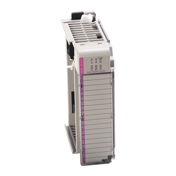
Page 195: 1769-Hsc
(2) Shaded bit positions must be set to 0. Entering a binary value greater than 1111101000 (greater than 1000 decimal) results in a configuration error. 1769-HSC Refer to the Compact High-speed Counter Module User Manual, publication 1769-UM006 for information on configuring the 1769-HSC module. Rockwell Automation Publication 1769-IN088A-EN-P - February 2011... - Page 196 Chapter 3 I/O Memory Mapping Notes: Rockwell Automation Publication 1769-IN088A-EN-P - February 2011...
- Page 197 • Terminal block: 1769-RTBN18 (1 per kit) • Door: 1769-RD (2 per kit) 1769-IT6 • Terminal block: 1769-RTBN18 (1 per kit) • Door label: 1769-RL2 series B (2 per kit) • Door: 1769-RD (2 per kit) Rockwell Automation Publication 1769-IN088A-EN-P - February 2011...
-
Page 198: Appendix A Module Replacement Parts
Not applicable 1769-ASCII Not applicable 1769-BOOLEAN • Terminal block: 1769-RTBN18 (1 per kit) • Door: 1769-RD (2 per kit) 1769-HSC • Terminal block: 1769-RTBN18 (1 per kit) • Door: 1769-RD (2 per kit) Rockwell Automation Publication 1769-IN088A-EN-P - February 2011... - Page 200 Rockwell Automation representative. New Product Satisfaction Return Rockwell Automation tests all of its products to ensure that they are fully operational when shipped from the manufacturing facility. However, if your product is not functioning and needs to be returned, follow these procedures.
Need help?
Do you have a question about the Allen-Bradley 1769-IA16 and is the answer not in the manual?
Questions and answers