Table of Contents
Advertisement
Advertisement
Table of Contents

Related Manuals for Rockwell Automation Allen-Bradley 1794-IB16D


Summary of Contents for Rockwell Automation Allen-Bradley 1794-IB16D
- Page 1 User Manual FLEX I/O Diagnostic Modules Catalog Numbers 1794-IB16D, 1794-OB16D...
- Page 2 IMPORTANT Identifies information that is critical for successful application and understanding of the product. Allen-Bradley, CompactLogix, ControlLogix, DriveLogix, FLEX, FlexLogix, Logix 5000, PLC-5, Rockwell Automation, RSLinx, RSLogix 5000, RSNetWorx, SoftLogix, and TechConnect are trademarks of Rockwell Automation, Inc. CIP, ControlNet, DeviceNet, and EtherNet/IP are trademarks of ODVA, Inc.
-
Page 3: Table Of Contents
Unused Output Channels........34 Configure Your Output Diagnostic Module......34 Rockwell Automation Publication 1794-UM061B-EN-P - March 2020... - Page 4 Ownership ........... 89 Rockwell Automation Publication 1794-UM061B-EN-P - March 2020...
- Page 5 1794-OB8EP 24V DC Electronically Protected 8 Output Module . . 1794-OB16 24V DC 16 Output Module ..... . 122 Rockwell Automation Publication 1794-UM061B-EN-P - March 2020...
- Page 6 ..............127 Rockwell Automation Publication 1794-UM061B-EN-P - March 2020...
-
Page 7: Preface
Also, see the appropriate sections in this publication, as well as Industrial Automation Wiring and Grounding Guidelines, Allen-Bradley publication 1770-4.1, for additional installation requirements pertaining to this equipment. Rockwell Automation Publication 1794-UM061B-EN-P - March 2020... - Page 8 ATTENTION: During mounting of all devices, be sure that all debris (such as metal chips or wire strands) is kept from falling into the module. Debris that falls into the module could cause damage on power-up. Rockwell Automation Publication 1794-UM061B-EN-P - March 2020...
-
Page 9: North American Hazardous Location Approval
S’assurer que l’environnement suitability for Class I, Division 2. est classé non dangereux avant de changer les piles. If this product contains batteries, they must only be changed in an area known to be nonhazardous. Rockwell Automation Publication 1794-UM061B-EN-P - March 2020... -
Page 10: Related Products And Documentation
4 Input/2 Output Analog Module 1794–OF4I 24V DC 4 Output Isolated Analog Module 1794-IN037 1794–6.5.8 1794–IF4I 24V DC 4 Input Isolated Analog Module 1794-IN038 1794–IF2XOF2I 24V DC 2 Input/2 Output Isolated Analog 1794-IN039 Module Rockwell Automation Publication 1794-UM061B-EN-P - March 2020... - Page 11 1794–OA8 120V AC 8 Output Module 1794-IN103 1794–OA8I 120V AC Isolated 8 Output Module 1794–OA16 120V AC 16 Output Module 1794–IM8 220V AC 8 Input Module 1794-IN104 1794–OM8 220V AC 8 Output Module Rockwell Automation Publication 1794-UM061B-EN-P - March 2020...
- Page 12 Analog 8 Output Module 1797-5.3 1797–IRT8 See note 8 Thermocouple/RTD Input Module 1797-5.4 1797–IJ2 See note 2 Channel Frequency Input Module 1797-5.9 1797–TB3 Cage Clamp Terminal Base 1797-5.1 1797–TB3S Spring Clamp Terminal Base 1797-5.2 Rockwell Automation Publication 1794-UM061B-EN-P - March 2020...
- Page 13 For more information on ControlNet® modules in Logix 5000 systems, see ControlNet Network Configuration User Manual, publication CNET-UM001. For more information on EtherNet/IP™ modules in Logix 5000 systems, see EtherNet/IP Network Devices User Manual, publication ENET-UM006. Rockwell Automation Publication 1794-UM061B-EN-P - March 2020...
- Page 14 Preface Notes: Rockwell Automation Publication 1794-UM061B-EN-P - March 2020...
-
Page 15: Introduction
• Open input or output wiring • Shorted output field devices • Shorted input or output wiring • Reversed polarity of user supply wiring • Open user supply wiring or failed user supply (using one diagnostic input channel) Rockwell Automation Publication 1794-UM061B-EN-P - March 2020... -
Page 16: Network Compatibility
• the voltage necessary for your application. • current leakage through the input devices. • the amount of current consumed by the input devices. • whether the application requires sinking or sourcing devices. Rockwell Automation Publication 1794-UM061B-EN-P - March 2020... -
Page 17: 1794-Ob16D Diagnostic Output Module Compatibility
• capable of 2 A surge for 50 ms, repeatable every 2 s. • protection from short circuit and overload. You need a dummy resistor to mask the channel diagnostic function for each unused output channel. Rockwell Automation Publication 1794-UM061B-EN-P - March 2020... -
Page 18: Install Your Digital Input Or Output Module
Mount the terminal base unit See installation instructions 1794-IN096. Install the module in the terminal base unit See installation instructions 1794-IN096. Connect the wiring to the terminal base unit See installation instructions 1794-IN096. Rockwell Automation Publication 1794-UM061B-EN-P - March 2020... - Page 19 Return COM 1 and COM 2 are internally connected together in the module) 3-wire devices only. 2-wire devices use input and sensor power terminals; 3-wire devices use input, sensor power and common terminals. Rockwell Automation Publication 1794-UM061B-EN-P - March 2020...
- Page 20 C-34 and C-51 (1794-TB2) (Power Terminals are internally connected in the terminal base unit. C-34…C-51 (1794-TB3, 1794-TB3S) (Power terminals are internally connected in the terminal base unit. Common B-16…B-33 (Common terminals are internally connected in the terminal base unit. Rockwell Automation Publication 1794-UM061B-EN-P - March 2020...
-
Page 21: Introduction
The module detects: • an open fault if the sensor-power current drops. • a short fault if the sensor-power voltage goes low. • a reverse-polarity fault if reverse voltage is applied to the user terminals. Rockwell Automation Publication 1794-UM061B-EN-P - March 2020... - Page 22 The recommended value of this dummy resistor is 20 k(+10%), 1/8 watt (or larger). Connect the resistor between sensor power and input signal or between sensor power and common. Rockwell Automation Publication 1794-UM061B-EN-P - March 2020...
-
Page 23: Diagnostic Fault Detection
1794-IB16D diagnostic input module. Reverse Reverse User Power Voltage Monitor Shorted Input Monitor Short Fault Indicator Open Sensor Power Open Wire Monitor Input Input Input Circuit Indicator Rockwell Automation Publication 1794-UM061B-EN-P - March 2020... -
Page 24: Sensor Power Open And Short Circuit Detection
The yellow input indicator is in series with the input signal (field-side indication). FLEX I/O system-side logic voltages are isolated from the user power supply and input channels by optocouplers. This provides protection against field side voltages and transients. Rockwell Automation Publication 1794-UM061B-EN-P - March 2020... -
Page 25: User Power Supply Reverse Voltage Detection
– Red indicates either a channel sensor power open or short condition. • Module Fault Status- This indictor turns red for any individual input channel open, short, or module reverse power conditions. With no fault, the module fault status indicator turns off. Rockwell Automation Publication 1794-UM061B-EN-P - March 2020... -
Page 26: Module Limitations
You must derate the allowable current from each channel sensor-power port based on operating ambient temperature to keep module power dissipation to an acceptable level. Sensor Power Current (mA) Ambient Temperature (˚ C) Rockwell Automation Publication 1794-UM061B-EN-P - March 2020... -
Page 27: Unused Sensor Power Ports
User Power Fault if: 1 < 50 A Overcurrent causes PTC to open 24V DC External Sensor User Power Supply Vsensor = (Ext Pwr) - 2.2V Voltage Drop = 2.2V maximum User Power Input Rockwell Automation Publication 1794-UM061B-EN-P - March 2020... -
Page 28: Configure Your Diagnostic Input Module
Filter time 1 0.5 ms Filter time 2 1 ms Filter time 3 2 ms Filter time 4 4 ms Filter time 5 8 ms Filter time 6 16 ms Filter time 7 32 ms Rockwell Automation Publication 1794-UM061B-EN-P - March 2020... -
Page 29: Introduction
• the module error bit is set. When a user supply reverse-polarity fault is detected: • the modules red fault indicator is turned on, • and the reverse error bit is set. • the module error bit is set. Rockwell Automation Publication 1794-UM061B-EN-P - March 2020... -
Page 30: Wiring Output Loads
Output channels are not isolated from one another. All 16 channels share a common return (group isolation from FLEX I/O system-side logic voltages). FLEX TB2/3/3S Terminal Base Output A0-A15 Output Device Common B17-B32 24V DC External User Power Supply Rockwell Automation Publication 1794-UM061B-EN-P - March 2020... -
Page 31: Diagnostic Fault Detection
1794-OB16D diagnostic output module. Reverse Reverse Voltage User Power Monitor Output Indicator Output Current Limiting Thermal Prot. Output FET Open Open Wire Detect Open Wire Current Monitor Fault Indicator Short Shorted Output Output Monitor 40117C Rockwell Automation Publication 1794-UM061B-EN-P - March 2020... -
Page 32: Module Protection Functions
If the on-state output channel short is removed, the output automatically recovers and voltage appears at the output, thus driving the attached load on. Rockwell Automation Publication 1794-UM061B-EN-P - March 2020... -
Page 33: Output Fault & Idle States With Network Communication Failure
See documentation for your FLEX I/O adapter and associated processor or controller for further information. Indicator Status Information The 1794-OB16D diagnostic output module has status indicators that allow you to check the module health and operational status. Rockwell Automation Publication 1794-UM061B-EN-P - March 2020... -
Page 34: Module Limitations
Diagnostic status is read from Word 1: Bit 00: Module Error Bit Bit 01: External Power Reverse Polarity Error Bit Bit 02: Output Short Error Bit Bit 03: Output Open Wire Error Bit Rockwell Automation Publication 1794-UM061B-EN-P - March 2020... -
Page 35: Chapter Objectives
Add a 1794-ASB adapter to the project Configuring Block Transfer Modules Create a Block Transfer (Read or Write) Message Instruction Remote I/O Network ControlLogix Chassis with 1756-DHRIO module 1771-ASB Adapter PLC-5® Controller in Adapter Mode 1747-ASB Adapter 1794-ASB Adapter Rockwell Automation Publication 1794-UM061B-EN-P - March 2020... -
Page 36: Add A 1756-Dhrio Module
B. Click the + to the nonisolated left of the Communications group to display the communication modules available. C. Select the series of 1756-DHRIO module you are using in your configuration. D. Click OK. Rockwell Automation Publication 1794-UM061B-EN-P - March 2020... - Page 37 Open Module Properties Verify that this box is checked to access all available configuration screens for the module. If this box is not checked, clicking OK assigns the default parameters for the remaining configuration fields. Rockwell Automation Publication 1794-UM061B-EN-P - March 2020...
- Page 38 Place a check mark in this box if you want a major fault to occur on the controller if the connection Mode between the controller and the DHRIO module is lost. Leaving this box unchecked means that failure to connect to the DHRIO module will not cause a major controller fault. Rockwell Automation Publication 1794-UM061B-EN-P - March 2020...
-
Page 39: Add A 1794 Remote Adapter Module
A. Define the following parameters: • Name • Rack # • Starting Group • Size • Open Module Properties See the 1794-ASB Adapter Module Properties Dialog Box table for additional information. B. Click OK. Rockwell Automation Publication 1794-UM061B-EN-P - March 2020... - Page 40 For example, if you are using 4 adapters on Channel A of the 1756 DHRIO module that is configured for a baud rate of 57.6 Kbaud, the recommended RPI for all adapters would be: (0.5 ms x 4 adapters x 8 ms per adapter = 16 ms) Rockwell Automation Publication 1794-UM061B-EN-P - March 2020...
- Page 41 ATTENTION: If communication with a module fails, the controller operates on old data from the module. To avoid potential injury or damage, either monitor communications with modules or configure modules to produce a major fault if communications fail. Rockwell Automation Publication 1794-UM061B-EN-P - March 2020...
-
Page 42: Configure Digital Modules
B. Depending on the type of Block I/O module you are using, expand the Analog or Digital list by clicking on the + sign to the left of the group. C. Right-click on RIO-MODULE to highlight. D. Click OK. Rockwell Automation Publication 1794-UM061B-EN-P - March 2020... - Page 43 0, 1, 2 or 3. Slot Enter the location of the remote I/O module. Open Module Properties Uncheck this box. There are no additional module properties to configure for the module. Rockwell Automation Publication 1794-UM061B-EN-P - March 2020...
-
Page 44: Create A Block Transfer (Read Or Write) Message Instruction
Controller to view the I/O tags. 1. Access the project’s Main Routine of ladder logic in the controller organizer. A. Right-click on Main Routine. B. Click Open in the pull-down menu. Rockwell Automation Publication 1794-UM061B-EN-P - March 2020... - Page 45 Data Type Choose Message type. Scope Message Tags can only be created within the Controller Scope. Open Message Configuration Verify that this box contains a check mark to access all available configuration screens. Rockwell Automation Publication 1794-UM061B-EN-P - March 2020...
- Page 46 (that is, browse to a tag) or, click New Tag to create the tag for the controller where data is placed to be transferred to the I/O module. When creating a tag, be sure to select Controller as the scope and assign Integer (INT) as the data type. Rockwell Automation Publication 1794-UM061B-EN-P - March 2020...
- Page 47 Clearing this box means that the connection will be uncached. An uncached connection is a connection between two points that opens only when a message is enabled and closes when the controller completes the block transfer. Uncached connections are not as fast as cached connections. Rockwell Automation Publication 1794-UM061B-EN-P - March 2020...
-
Page 48: Ladder Logic Examples
The following illustration provides you with a ladder logic example for 1794 diagnostic modules. The example is typical ControlLogix software ladder rungs for block transfer message instructions Ladder Logic Example for 1794 Diagnostic Modules. Rockwell Automation Publication 1794-UM061B-EN-P - March 2020... -
Page 49: How To Use This Chapter
This may make your programming easier. Assign one address for the 1794-ADN and all modules that you connect to it. If You Configure the Adapter Offline Set the Address of the Adapter Rockwell Automation Publication 1794-UM061B-EN-P - March 2020... -
Page 50: Rslogix 5000 Software
• If you want to only use the ASCII representation of scanner status/display, then set the Status Size = 10. • If you also want to read the status code of the scanner, set the Status Size = 11. Rockwell Automation Publication 1794-UM061B-EN-P - March 2020... - Page 51 – 5 DINTs status code of lower 32 devices – 1 byte per device DeviceStatus SINT[32] status code of all devices – 1 byte per device DeviceStatus SINT[64] Rockwell Automation Publication 1794-UM061B-EN-P - March 2020...
-
Page 52: Add The Scanner To The I/O Configuration Folder
1. Right-click and choose New Module. SoftLogix 5800 scanners EtherNet/IP to DeviceNet linking device ControlNet to DeviceNet linking device 2. Choose the type of scanner. 3. Select the major revision of the scanner. Rockwell Automation Publication 1794-UM061B-EN-P - March 2020... -
Page 53: Define The Properties Of The Scanner
2. Choose Next. 3. Choose Next. 4. Choose Browse and find the RSNetWorx configuration file for the network (.dnt file). The default path for the file is …\Program Files\Rockwell Software\RSNetWorxII\Networks. 5. Choose Finish. Rockwell Automation Publication 1794-UM061B-EN-P - March 2020... -
Page 54: Determine The Address Of Devicenet Data
If the data is: Then type is: input from a device output to a device status of the network element specific DINT (DWord, 32-bit integer) within the array specific bit within an integer Rockwell Automation Publication 1794-UM061B-EN-P - March 2020... - Page 55 0 0 0 0 0 0 0 0 0 0 0 0 0 0 0 0 0 0 0 0 0 0 0 0 0 0 0 0 0 0 0 0 data map for Bulletin 160 AC drive Rockwell Automation Publication 1794-UM061B-EN-P - March 2020...
-
Page 56: Tally Memory Requirements
As an option, give each module its own memory location (DINTs) within the scanner. This may make your programming easier. Assign one address for the 1794-ADN and all modules that you connect to it. DeviceNet network Rockwell Automation Publication 1794-UM061B-EN-P - March 2020... -
Page 57: If You Configure The Adapter Offline
If you configure the FLEX I/O adapter offline, check the I/O sizes of each module. For FLEX I/O, RSNetWorx software uses offline I/O sizes that differ Adapter Offline from the default values of the modules. Online offline online Offline Configuration configuration configuration Configuration Rockwell Automation Publication 1794-UM061B-EN-P - March 2020... -
Page 58: Set The Address Of The Adapter
It then sets its baud rate to that of the other device. For more information on using DeviceNet in Logix 5000 control systems, see DeviceNet Network Configuration User Manual, publication DNET-UM004. Rockwell Automation Publication 1794-UM061B-EN-P - March 2020... -
Page 59: Introduction
You can also validate connections to distributed I/O when controlling it over ControlNet. This task is useful when one or more of the connections are not working but is not required, especially when all connections appear to work normally. Rockwell Automation Publication 1794-UM061B-EN-P - March 2020... -
Page 60: Set Up The Hardware
Each I/O module has a limit of how many packets it can handle per second. If you exceed this limit, the module cannot open any more connections. Rockwell Automation Publication 1794-UM061B-EN-P - March 2020... -
Page 61: Select A Communication Format
• Some or all remote I/O communicating with a controller via the remote ControlNet communication module use a Rack Optimized communication format. • The connection is going to read inputs but is not going to be controlling outputs. Rockwell Automation Publication 1794-UM061B-EN-P - March 2020... - Page 62 A Listen Only communication format that matches the module. data the I/O module is broadcasting to other controllers. See online help in RSLogix 5000 programming software for specific communication formats per I/O module. Rockwell Automation Publication 1794-UM061B-EN-P - March 2020...
-
Page 63: Direct Or Rack-Optimized Connection
ControlNet communication module the owner-controller still makes direct connections with the 3 I/O modules that are configured as such. You can only make up to 5 rack-optimized connections to one remote ControlNet communication module. Rockwell Automation Publication 1794-UM061B-EN-P - March 2020... - Page 64 In this case, use rack-optimized connections to conserve connection use and network traffic. Rockwell Automation Publication 1794-UM061B-EN-P - March 2020...
- Page 65 I/O modules. To increase the number of available connections, use a rack-optimized connection to any remote adapter with multiple digital I/O modules that allow rack-optimized connection, instead of direct connections to those I/O modules. Rockwell Automation Publication 1794-UM061B-EN-P - March 2020...
-
Page 66: Ownership
It does not write configuration data and con only maintain a connection to the I/O module when the owner controller is actively controlling the I/O module. Rockwell Automation Publication 1794-UM061B-EN-P - March 2020... -
Page 67: Add Local And Remote Controlnet Modules
RSLogix 5000 project. For more detailed information on how to add local and remote ControlNet modules to your project, refer to publication CNET-UM001. 1. Add Local ControlNet Communication Module 2. Add Remote ControlNet Communication Module Rockwell Automation Publication 1794-UM061B-EN-P - March 2020... -
Page 68: Add Distributed I/O
Do these steps to add distributed I/O to your RSLogix 5000 project: 1. Add the local ControlNet communications modules, add the ControlNet adapter for the distributed I/O. 2. Add the distributed I/O module. Rockwell Automation Publication 1794-UM061B-EN-P - March 2020... - Page 69 Open Module Properties is checked, clicking OK will automatically take you to next tab. After you complete adding all FLEX I/O modules to your project file, you must download the project to your Logix 5000 controller. Rockwell Automation Publication 1794-UM061B-EN-P - March 2020...
-
Page 70: Download The Program To The Controller
3. From the Who Active dialog, choose Set Project Path. 4. From the Who Active dialog, choose Download to see the Download dialog. 5. From the Download dialog, choose Download. You see this RSLogix 5000 dialog. Rockwell Automation Publication 1794-UM061B-EN-P - March 2020... -
Page 71: Configure The 1794-Acn15 Adapter
This procedure will synchronize the chassis size value from the RSLogix 5000 software into the 1794-ACN15 adapter. 1. Highlight the 1794-ACN15 adapter, and right-click to choose Properties. Verify the node address and the chassis size. Rockwell Automation Publication 1794-UM061B-EN-P - March 2020... -
Page 72: Schedule I/O Module Connections
RSNetWorx for ControlNet. Schedule I/O Module Use these procedures to schedule I/O module connections. Connections 1. Start RSNetWorx for ControlNet. 2. From the File menu, choose New. 3. Click OK. 4. Choose Network>Online. Rockwell Automation Publication 1794-UM061B-EN-P - March 2020... - Page 73 Chapter 6 5. Browse to ControlNet Selection dialog. 6. Click OK. When you are online, you see the following dialog. 7. Choose Edits Enabled in the top left of the dialog. File and Save. Rockwell Automation Publication 1794-UM061B-EN-P - March 2020...
- Page 74 8. Click OK. 9. Give the RSNetWorx file a unique name, if desired. 10. If the file exists, you are prompted before overwriting it. 11. Click OK. 12. The network is verified, and configured, Rockwell Automation Publication 1794-UM061B-EN-P - March 2020...
- Page 75 These values are set to 99 by default. Change these values to what is installed in your system. This saves you time because the controller will not have to search for all node addresses. Rockwell Automation Publication 1794-UM061B-EN-P - March 2020...
- Page 76 You see the Save Configuration dialog. 22. Click OK. 23. Minimize the RSNetworx for Controlnet window, and open your RSLogix 5000 window. 24. Notice the I/O OK is solid green in your RSLogix 5000 project. Rockwell Automation Publication 1794-UM061B-EN-P - March 2020...
-
Page 77: Access Module Data Via The 1794-Acn15 Adapter
• # = slot number of FLEX I/O module (0…7) • C = configuration, I = input, O = output When there is no slot number, that is the rack-optimized data. Here are some typical sample configuration data examples. Rockwell Automation Publication 1794-UM061B-EN-P - March 2020... - Page 78 ACN15:4:I (1794-OB16D module) input data ACN15:4:O (1794-OB16D module) output data It is also possible to send configurations via CIP™ messages. Use the controller tags in your ladder program to read input data or write output data. Rockwell Automation Publication 1794-UM061B-EN-P - March 2020...
-
Page 79: Slot Status Bits
I/O module. To download the new configuration, you must reinitiate the connection to the I/O module. This download is best achieved by inhibiting and uninhibiting the module. Rockwell Automation Publication 1794-UM061B-EN-P - March 2020... - Page 80 5. Click the Connection tab. 6. Check the Inhibit Module checkbox. When you inhibit an adapter, all modules are inhibited. When you inhibit a module, only the module is inhibited, not the whole rack. 7. Click Apply. Rockwell Automation Publication 1794-UM061B-EN-P - March 2020...
- Page 81 8. Click OK to confirm disabling the connection. The connection is now inhibited. 9. Uncheck the Inhibit Module checkbox to disable the inhibit module function. 10. Click Apply to download the configuration data. 11. Click Yes. Rockwell Automation Publication 1794-UM061B-EN-P - March 2020...
- Page 82 Chapter 6 Configure Your Adapter and Digital Modules on a ControlNet Network 12. The connection status is now Running, and the module is using the updated configuration data. Rockwell Automation Publication 1794-UM061B-EN-P - March 2020...
-
Page 83: How To Use This Chapter
• Use the I/O information in RSLogix 5000 software. You can also validate connections to distributed I/O when controlling it over Ethernet. This task is useful when one or more of the connections are not Rockwell Automation Publication 1794-UM061B-EN-P - March 2020... -
Page 84: Set Up The Hardware
Configure your Digital Module on an EtherNet/IP Network working but is not required, especially when all connections appear to work normally. When you first install a Rockwell Automation EtherNet/IP module (right out of the box), the module is BOOTP/DHCP enabled. Set Up the Hardware In this example, the Logix 5000 controller has an EtherNet/IP communication module to connect to the EtherNet/IP network. -
Page 85: Select A Communication Format
Analog Module a direct connection Float Data... Integer Data (only direct connection is CST Timestamped... supported for analog modules) See online help in RSLogix 5000 programming software for specific communication formats per I/O module. Rockwell Automation Publication 1794-UM061B-EN-P - March 2020... -
Page 86: Choose Direct Or Rack-Optimized Connection
I/O modules in the chassis (or DIN rail). Rather than having individual, direct connections for each I/O module, there is one connection for the entire chassis (or DIN rail). Rack-optimized Connection Rockwell Automation Publication 1794-UM061B-EN-P - March 2020... - Page 87 See Rack-optimized Connections For I/O Modules on page 86 to conserve connection use and network traffic. Rockwell Automation Publication 1794-UM061B-EN-P - March 2020...
- Page 88 To optimize the number of available connections, use a rack-optimized connection between any digital I/O that allow it and the remote adapter that connects the distributed I/O to the controller via the communication module. Rockwell Automation Publication 1794-UM061B-EN-P - March 2020...
-
Page 89: Ownership
Select a Remote Adapter The remote adapter that you use depends on the distributed I/O you use. When using FLEX I/O modules, you use the FLEX I/O adapter, cat. no. 1794-AENT, which requires the BOOTP utility. Rockwell Automation Publication 1794-UM061B-EN-P - March 2020... -
Page 90: Add Distributed I/O
…you build the I/O configuration in this order. 1. Add the local communication module (bridge). 2. Add the remote adapter for the distributed I/O chassis or DIN rail. 3. Add the I/O module. Rockwell Automation Publication 1794-UM061B-EN-P - March 2020... -
Page 91: Add A Module
Follow this procedure to download the program you saved to the ControlLogix controller. the Controller 1. From the main menu, choose Communication>Who-Active. 2. Select the processor slot in the chassis. 3. From the Who-Active dialog, choose Set Project Path. Rockwell Automation Publication 1794-UM061B-EN-P - March 2020... - Page 92 Configure your Digital Module on an EtherNet/IP Network 4. From the Who Active dialog, choose Download to see the Download dialog. 5. From the Download dialog, choose Download. 6. Click OK. 7. Your system is now up and running. Rockwell Automation Publication 1794-UM061B-EN-P - March 2020...
-
Page 93: Access Distributed I/O
Specific data that is related to a MemberName. Bit (optional) Specific point on the I/O module; depends on the size of the I/O module (0…31 for a 32-point module) EXAMPLE Example 1 Example 2 Rockwell Automation Publication 1794-UM061B-EN-P - March 2020... - Page 94 In your logic, you see the tag of the device as aliases for a tag of the adapter. (The tag name of the adapter is in angle brackets). tag name of the I/O device tag name of the adapter conveyor:2:I.0 <conveyor:I.Data[2].0> Rockwell Automation Publication 1794-UM061B-EN-P - March 2020...
-
Page 95: General Information About Ip Addresses
A gateway connects individual physical networks into a system of networks. When a node needs to communicate with a node on another network, a gateway transfers the data between the two networks. This field is set to 0.0.0.0 by default. Rockwell Automation Publication 1794-UM061B-EN-P - March 2020... -
Page 96: Assigning Network Parameters Via The Bootp/Dhcp Utility
Check with your Ethernet network administrator to determine if you must specify all of the above parameters. To configure these network parameters, the recommended method is to use the Rockwell Automation BOOTP/DHCP utility. If this utility is not available, there are other methods that you can use. Assigning Network By default, the EtherNet/IP module is BOOTP enabled. - Page 97 3. Double-click the hardware (MAC) address of the module you want to configure. The hardware address is on a sticker that is on the side of the EtherNet/IP module. The hardware address will be in a format similar to: 00-0b-db-14-55-35. Rockwell Automation Publication 1794-UM061B-EN-P - March 2020...
- Page 98 BOOTP request. If you do not select the Disable BOOTP/DHCP button, on a power cycle, the host controller clears the current IP configuration and will again begin sending BOOTP requests. Rockwell Automation Publication 1794-UM061B-EN-P - March 2020...
-
Page 99: Using Other Methods To Assign Network Parameters
• type of training offered to control engineers and maintenance personnel If you use the Rockwell Automation BOOTP or DHCP server in an uplinked subnet where an enterprise DHCP server exists, a module may get an address from the enterprise server before the Rockwell Automation utility even sees the module. -
Page 100: Using Rslinx Software To Set The Ip Address
5. Also, select the Static radio button to permanently assign this configuration to the port. If you select Dynamic, on a power cycle, the controller clears the current IP configuration and will again begin sending BOOTP requests. Rockwell Automation Publication 1794-UM061B-EN-P - March 2020... -
Page 101: Using Rslogix 5000 Software To Set The Ip Address
3. Start RSLogix 5000 software. In the Controller Organizer, select properties for the EtherNet/IP module. 4. Select the Port Configuration tab and specify the IP address and the other network parameters, if needed. Click Apply and then click OK. Rockwell Automation Publication 1794-UM061B-EN-P - March 2020... -
Page 102: Using Dhcp Software To Set The Ip Address
If the module determines that there is a conflict (some other device on the network already has the IP address), the EtherNet/IP port of the module goes into conflict mode, where the module’s: Rockwell Automation Publication 1794-UM061B-EN-P - March 2020... -
Page 103: Duplicate Detection Scenarios
IP address, regardless of which module obtains the IP address first. The module that supports duplicate IP address detection will detect the conflict and give up the IP address. Rockwell Automation Publication 1794-UM061B-EN-P - March 2020... -
Page 104: Ip Address Swapping
During a switchover in ControlLogix redundancy systems, these modules swap their IP addresses with their partner modules in the other redundant chassis. For more information about IP address swapping, see the ControlLogix Redundancy System User Manual, publication 1756-UM523. Rockwell Automation Publication 1794-UM061B-EN-P - March 2020... -
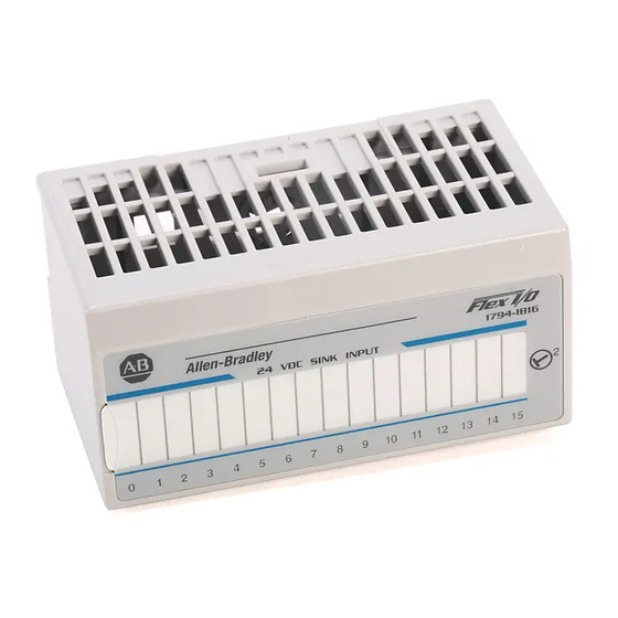
Page 105: Interpret The Indicators
24 VDC SINK INPUT WITH DIAGNOSTIC Allen-Bradley 1794-OB16D 24 VDC SOURCE OUTPUT WITH DIAGNOSTIC Where: 1 = Channel bicolor Status indicator 2 = Insertable label for writing individual input/output designations 3 = Module bicolor Fault Indicator Rockwell Automation Publication 1794-UM061B-EN-P - March 2020... -
Page 106: 1794-Ib16D Diagnostic Functional Details
A dummy resistor must be placed across the contacts of contact input devices (for example, switches). Use 20 k resistors. Fault Device State Fault Indicators Error Bit Conditions Status Field Device Input Status Module Fault Channel Fault Rockwell Automation Publication 1794-UM061B-EN-P - March 2020... - Page 107 Shorted Input Signal/ Common Short and Module Shorted Input Signal/ Common Reverse User Power OFF or ON Reverse and Module User power supply wiring is reversed If sensor can pass Sensor Power short circuit current Rockwell Automation Publication 1794-UM061B-EN-P - March 2020...
-
Page 108: Diagnostic Functions For The 1794-Ib16D
The module monitors each sensor-power port for current and voltage. It turns on the channel red LED and sets (1) the error bit when 1) the module detects a short circuit (no voltage at the sensor-port), and 2) the module detects an open wire (no current at the sensor-port). Rockwell Automation Publication 1794-UM061B-EN-P - March 2020... -
Page 109: 1794-Ob16D Diagnostic Functional Details
Can’t detect an open in the ON-state Short Short and Module Short - output to Common None Can’t detect a short in the OFF-state Reverse OFF or ON Reverse and Module User power supply wiring is reversed User Power Rockwell Automation Publication 1794-UM061B-EN-P - March 2020... -
Page 110: Diagnostic Functions For The 1794-Ob16D
(the output signal is active at a channel and the corresponding output voltage is low), and 2) the module detects an open wire (the output signal is inactive at a channel and the corresponding output voltage is high). Rockwell Automation Publication 1794-UM061B-EN-P - March 2020... -
Page 111: Simplified Schematics Of Flex I/O Digital Modules
24V DC 16 protected sink output module 48V DC 1794-IC16 Input 48V DC 16 sink input module 1794-OC16 Output 48V DC 16 source output module 24V DC 1794-OW8 Output 24V DC 8 relay output module Rockwell Automation Publication 1794-UM061B-EN-P - March 2020... -
Page 112: 1794-Ia8 120V Ac 8 Input Module
Filter Isolation Device (B-0) 85…132V AC Common L2 (C-1) 40945 Note: To maintain isolation, separate AC sources must be used with each channel. Auxiliary terminal strips are required for all terminal base units. Rockwell Automation Publication 1794-UM061B-EN-P - March 2020... -
Page 113: 1794-Ia16 120V Ac 16 Input Module
Typical Simplified Schematic for Output 0 C-34 and a 1794-TB2, 1794-TB3, 1794-TB3S, or (1794-TBN, 1794-TBNF) Terminal Base Flexbus Opto (B-0) Interface Isolation Output 85…132V AC Device (C-1) *Fuse on 1794-TBNF only B-16 Common L2 40105 Rockwell Automation Publication 1794-UM061B-EN-P - March 2020... -
Page 114: 1794-Oa8I 120V Ac 8 Output Module
Typical Simplified Schematic for Output 0 C-34 and a 1794-TBN Terminal Base 85…132V AC Flexbus Opto Output Interface Isolation Device Note: Auxiliary terminal strips are required when using the 1794-TBN with the 1794-OA16 module. 40944A Rockwell Automation Publication 1794-UM061B-EN-P - March 2020... -
Page 115: 1794-Im 8 220V Ac 8 Input Module
1794-OM8 220V AC 8 Output Module Typical Simplified Schematic for Output 0 C-34 and 1794-TBN or 1794-TBNF Terminal Base 170…264V AC Flexbus Output Opto Interface Isolation Device B-16 41701 Fuse on 1794-TBNF only Rockwell Automation Publication 1794-UM061B-EN-P - March 2020... -
Page 116: 1794-Ib8 24V Dc 8 Input Module
Interface C-34 B-16 40107 1794-IB16 24V DC 16 Input Module Typical Simplified Schematic for Input 0 and a 1794-TB3 or 1794-TB3S Terminal Base Opto Isolation Input Device Flexbus C-35 Interface C-34 B-16 40107 Rockwell Automation Publication 1794-UM061B-EN-P - March 2020... -
Page 117: 1794-Ib16D 24V Dc 16 Diagnostic Input Module
Use a 20 KΩ dummy resistor on unused input channels and on inputs that have hard-contact input devices. The dummy resistors can be placed between sensor power and the input channel, or between sensor power and common. Rockwell Automation Publication 1794-UM061B-EN-P - March 2020... -
Page 118: 1794-Ib32 24V Dc 32 Input Module
Typical Simplified Schematic for Input 0 and Input 16 and a 1794-TB32 or 1794-TB32S Terminal Base Opto Isolation Input Flexbus Device C-37 Interface C-35 COM 1 C-36 Opto Isolation B-17 Input Flexbus Device C-45 Interface C-43 COM 2 C-44 0107 Rockwell Automation Publication 1794-UM061B-EN-P - March 2020... -
Page 119: 1794-Ib10Xob6 24V Dc 8 10 Input/6 2A Output Module
Input Device Flexbus C-35 Interface C-34 B-16 40123 Typical Simplified Schematic for Output 0 and a 1794-TB3 or 1794-TB3S Terminal Base C-34 +24V Opto Isolation A-10 Flexbus Interface Output Device B-27 B-16 40124 Rockwell Automation Publication 1794-UM061B-EN-P - March 2020... -
Page 120: 1794-Ib16Xob16P 24V Dc 16 Input/16 Output Module
1794-TB32 or 1794-TB32S Terminal Base Opto Isolation Input Flexbus Device C-37 Interface C-35 C-36 COM 1 C-43 +24V Current Limit Circuit Thermal Protection Output FET B-17 ASIC Output Device C-46 COM 2 C-44 Rockwell Automation Publication 1794-UM061B-EN-P - March 2020... -
Page 121: 1794-Iv16 24V Dc 16 Source Input Module
1794-OB8 24V DC 8 Output Module Typical Simplified Schematic for Output 0 and a 1794-TB2, 1794-TB3, or 1794-TB3S Terminal Base C-34 +24V Opto Isolation Flexbus Interface Output Device B-17 B-16 40117 Rockwell Automation Publication 1794-UM061B-EN-P - March 2020... -
Page 122: 1794-Ob8Ep 24V Dc Electronically Protected 8 Output Module
B-16 40117 1794-OB16 24V DC 16 Output Module Typical Simplified Schematic for Output 0 and a 1794-TB2, 1794-TB3, or 1794-TB3S Terminal Base C-34 +24V Opto Isolation Flexbus Interface Output Device B-17 B-16 40117 Rockwell Automation Publication 1794-UM061B-EN-P - March 2020... -
Page 123: 1794-Ob16D 24V Dc 16 Diagnostic Output Module
1794-OB16P 24V DC 16 Output Module Typical Simplified Schematic for Output 0 and a 1794-TB2, 1794-TB3, or 1794-TB3S Terminal Base C-34 +24V Current Limit Circuit Thermal Protection Output FET ASIC Output Device B-17 B-16 41017 Rockwell Automation Publication 1794-UM061B-EN-P - March 2020... -
Page 124: 1794-Ob32P 24V Dc 32 Output Module
+24V Current Limit Circuit Thermal Protection Output FET ASIC Output Device C-38 COM 1 C-36 C-43 +24V Current Limit Circuit Thermal Protection Output FET B-17 ASIC Output Device C-46 COM 2 C-44 41017 Rockwell Automation Publication 1794-UM061B-EN-P - March 2020... -
Page 125: 1794-Ov16 24V Dc 16 Sink Output Module
1794-OV16P 24V DC 16 Sink Output Module Typical Simplified Schematic for Output 0 and a 1794-TB3 or 1794-TB3S Terminal Base C-34 Opto C-35 Isolation Output Flexbus Device Interface Current Limit Circuit Thermal Protection Output FET B-16 40115 Rockwell Automation Publication 1794-UM061B-EN-P - March 2020... -
Page 126: 1794-Ic 48V Dc 16 Input Module
40146 Note: Auxiliary terminal strips are required for all terminal base units except the 1794-TB3 Fuse on 1794-TBNF only and 1794-TB3S when load power is 24V DC and channel-to-channel isolation is not needed. Rockwell Automation Publication 1794-UM061B-EN-P - March 2020... - Page 127 I/O over ControlNet adding distributed I/O to an RSLogix 5000 project 68 module data requested packet interval 60 access 77 device network parameters 99 address data 54 DeviceNet FLEX I/O 49 DHCP software 102 Rockwell Automation Publication 1794-UM061B-EN-P - March 2020...
- Page 128 60 swap IP addresses 104 RPI 84 RSLinx configuring network parameters 100 RSLogix 5000 adding distributed I/O to an RSLogix 5000 project 68 communication format 61 RSLogix 5000 software 101 Rockwell Automation Publication 1794-UM061B-EN-P - March 2020...
- Page 129 Rockwell Automation Publication 1794-UM061B-EN-P - March 2020...
- Page 130 Rockwell Automation representative. New Product Satisfaction Return Rockwell Automation tests all of its products to ensure that they are fully operational when shipped from the manufacturing facility. However, if your product is not functioning and needs to be returned, follow these procedures.
Need help?
Do you have a question about the Allen-Bradley 1794-IB16D and is the answer not in the manual?
Questions and answers