
Related Manuals for Rockwell Automation Allen-Bradley 1790D-N4CO


Summary of Contents for Rockwell Automation Allen-Bradley 1790D-N4CO
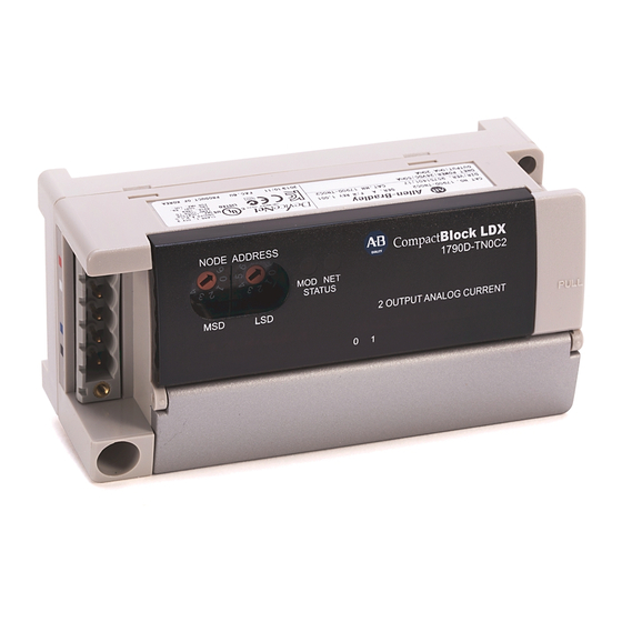
- Page 1 CompactBlock LDX I/O Analog Modules Catalog Numbers 1790D-N4CO, 1790D-TN4CO, 1790D-TN4V0, 1790D-N0C2, 1790D-TN0C2, 1790D-TN0V2, 1790P-TN4C0, 1790P-TN0C2 User Manual Original Instructions...
- Page 2 If this equipment is used in a manner not specified by the manufacturer, the protection provided by the equipment may be impaired. In no event will Rockwell Automation, Inc. be responsible or liable for indirect or consequential damages resulting from the use or application of this equipment.
-
Page 3: Table Of Contents
Analog Input Data Format ........29 Rockwell Automation Publication 1790-UM001B-EN-P - April 2021... - Page 4 Channel Status Indicator Operation ......44 Contacting Rockwell Automation....... . . 45...
- Page 5 Index ............61 Rockwell Automation Publication 1790-UM001B-EN-P - April 2021...
- Page 6 Table of Contents Notes: Rockwell Automation Publication 1790-UM001B-EN-P - April 2021...
-
Page 7: Preface
Industrial Automation Wiring and Grounding Guidelines, publication 1770-4.1 Provides general guidelines for installing a Rockwell Automation industrial system. Product Certifications website, rok.auto/certifications. Provides declarations of conformity, certificates, and other certification details. You can view or download publications at rok.auto/literature. - Page 8 Notes: Rockwell Automation Publication 1790-UM001B-EN-P - April 2021...
-
Page 9: How To Use Analog I/O
SLC™ 500 programmable controller. The module supports connections from any combination of up to four voltage or current analog sensors. The four high-impedance input channels can be wired as single-ended inputs. Rockwell Automation Publication 1790-UM001B-EN-P - April 2021... -
Page 10: Hardware Features
(D- hole shell shown) General Diagnostic Features The CompactBlock LDX I/O modules contain diagnostic features that can help you identify the source of problems that may occur during power-up or during Rockwell Automation Publication 1790-UM001B-EN-P - April 2021... -
Page 11: System Overview
Figure 2 - Input Module Circuitry Block Diagram Isolation Data Optocouplers Signal Input 0 Control Microcontroller XCVR DeviceNet Input 1 Input 2 Input 3 Select 24V DC Analog Field power Analog Power supply power Rockwell Automation Publication 1790-UM001B-EN-P - April 2021... - Page 12 Figure 3 - Output Module Circuitry Block Diagram Isolation Optocouplers Data Analog Output 0 output Microcontroller XCVR DeviceNet Control Analog Output 1 output 24V DC Analog Field Analog power Power power supply Rockwell Automation Publication 1790-UM001B-EN-P - April 2021...
-
Page 13: Power Requirements
AC motor drives • away from modules that generate significant radiated heat. In addition, route shielded, twisted-pair analog input and output wiring away from any high-voltage I/O wiring. Rockwell Automation Publication 1790-UM001B-EN-P - April 2021... -
Page 14: Protect The Circuit Board From Contamination
WARNING: When used in a Class I, Division 2, hazardous location, this equipment must be mounted in a suitable enclosure with proper wiring method that complies with the governing electrical codes. Rockwell Automation Publication 1790-UM001B-EN-P - April 2021... -
Page 15: Mount The Optional Expansion Blocks
15 cm (5.90 in.) ribbon cable (1790-15CMCBL) and alternately position the blocks in a right-side up, upside-down fashion. You can mount your blocks on a panel or DIN rail as described in the previous section. Rockwell Automation Publication 1790-UM001B-EN-P - April 2021... -
Page 16: Connect The Devicenet Cable
The required DeviceNet connector is not supplied with the block. You must purchase it separately. There are three types of connectors that you can order directly from Rockwell Automation or your local distributor: • 1799-DNETCON – 5-position open style connector •... -
Page 17: I/O System Wiring Guidelines
(1) In environments where high-frequency noise may be present, it may be necessary to directly ground cable shields to earth at the module end and via a 0.1 μF capacitor at the sensor end. Rockwell Automation Publication 1790-UM001B-EN-P - April 2021... - Page 18 [Rs + (2 x Rc) + Ri] Vs = Vin x In a current loop system, source and cable impedance do not impact system accuracy. Rockwell Automation Publication 1790-UM001B-EN-P - April 2021...
-
Page 19: Effect Of Device And Cable Output Impedance On Output Module
DC resistance of the Length of Cable (m) cable, Rc () 1000 10,000 100,000 0.0525 0.0605% 0.00605% 0.000605% 0.525 0.155% 0.0155% 0.00155% 2.625 0.575% 0.0575% 0.00575% 5.25 1.1% 0.11% 0.011% Rockwell Automation Publication 1790-UM001B-EN-P - April 2021... -
Page 20: Wiring The Modules
0.1 μF capacitor at the sensor end for analog inputs and at the load end for analog outputs. 4. At the other end of the cable, cut the drain wire and foil shield back to the cable. Rockwell Automation Publication 1790-UM001B-EN-P - April 2021... -
Page 21: 1790D-N4C0 Analog 4 Input Base D-Shell Module Wiring
1790D-TN4C0, 1790D-TN4V0 Analog 4 Input Base Module Wiring Table 6 lists the module pin descriptions. Figure 10 Figure 11 show how to wire each module. Table 6 - 1790D-TN4C0 and 1790D-TN4V0 Module Pin Description Pin Number Description +24V Rockwell Automation Publication 1790-UM001B-EN-P - April 2021... -
Page 22: 1790D-N0C2 Analog 2 Output Base D-Shell Module Wiring
Table 7 - 1790D-N0C2 Module Pin Description Pin Number Description Pin Number Description +24V +24V +24V Pin Number Description Pin Number Description NC = No Connect +24V = Field Power (+) 24V DC GND = Field Power (-) GND Rockwell Automation Publication 1790-UM001B-EN-P - April 2021... -
Page 23: 1790D-Tn0C2, 1790D-Tn0V2 Analog 4 Input Base Module Wiring
Pin Number Description +24V = Field Power (+) 24V DC GND = Field Power (-) GND Figure 13 - Example of Input Wiring to the 1790D-TN0C2 and 1790D-TN0V2 Module +24V – – 24V DC Rockwell Automation Publication 1790-UM001B-EN-P - April 2021... - Page 24 Chapter 2 Installation and Wiring Notes: Rockwell Automation Publication 1790-UM001B-EN-P - April 2021...
-
Page 25: Analog Input Image
Bit Position Word Not Used Analog Input Data Channel 0 Not Used Analog Input Data Channel 1 Not Used Analog Input Data Channel 2 Not Used Analog Input Data Channel 3 Not Used Rockwell Automation Publication 1790-UM001B-EN-P - April 2021... -
Page 26: Analog Input Data File With Discrete Input Expansion Module
Not used: Set to 0 Bits 00…11 Channel 2 input data Read Word 2 Bits 12…15 Not used: Set to 0 Bits 00…11 Channel 3 input data Read Word 3 Bits 12…15 Not used: Set to 0 Rockwell Automation Publication 1790-UM001B-EN-P - April 2021... - Page 27 Discrete Input expansion data Table 15 shows the structure for an analog base module with one of the following 16-input modules: • 1790-16BV0X, 1790-T16BV0X discrete expansion module and one of the following 8-input modules: Rockwell Automation Publication 1790-UM001B-EN-P - April 2021...
- Page 28 Not Used Analog Input Data Channel 3 Not Used Table 18 - Word/Bit Descriptions Word Decimal Bit Description Bits 00…11 Channel 0 input data Read Word 0 Bits 12…15 Not used: Set to 0 Rockwell Automation Publication 1790-UM001B-EN-P - April 2021...
-
Page 29: Analog Input Data Format
Configure Analog Modules To configure analog modules, follow these steps: with RSNetWorx 1. Open RSNetWorx for DeviceNet. 2. Add an analog input module (for example, 1790D-N4C0) to the network, as shown in Figure Rockwell Automation Publication 1790-UM001B-EN-P - April 2021... - Page 30 Figure 15 - General Module Properties 4. Click the Module Configuration tab. Analog input modules have a configuration dialog box similar to the dialog box shown in Figure 16 the 1790D-N4C0 module. Rockwell Automation Publication 1790-UM001B-EN-P - April 2021...
- Page 31 AMP range selection. Figure 17 - Parameters Tab Pull-down menu Click OK. 1. Use the pull-down menu to change range selection. 2. Click OK after making all configuration changes. Rockwell Automation Publication 1790-UM001B-EN-P - April 2021...
- Page 32 Chapter 3 Module Data, Status, and Channel Configuration for Analog Input Modules The Module Configuration dialog box displays. 3. Click Download to save your configuration. 4. Click OK after making all configuration changes. Rockwell Automation Publication 1790-UM001B-EN-P - April 2021...
-
Page 33: Analog Output Image
8-output modules: • 1790-8BV8BX, 1790-T8BV8BX discrete expansion module • 1790-8BV8VX, 1790-T8BV8VX discrete expansion module • 1790-TOA8X discrete expansion module • 1790-T0W8X discrete expansion module. Rockwell Automation Publication 1790-UM001B-EN-P - April 2021... - Page 34 1790-OB16X, 1790-TOB16X discrete expansion module • 1790-OV16X, 1790-TOV16X discrete expansion module and with one of the following 8-input modules • 1790-8BV8BX, 1790-T8BV8BX discrete expansion module • 1790-8BV8VX, 1790T8BV8VX discrete expansion module • 1790-TOA8X discrete expansion module Rockwell Automation Publication 1790-UM001B-EN-P - April 2021...
-
Page 35: Analog Output Data Format
Output Full Scale Module HEX Data Range Decimal Data Range Output Resolution Range 1790D-TNOV2 0…10V DC 0000 0FFF 4095 2.44 mV … … 1790D-N0C2 0…20 mA 0000 0FFF 0…4095 4.88 A … 1790D-TNOC2 Rockwell Automation Publication 1790-UM001B-EN-P - April 2021... -
Page 36: Output Fault And Idle States
Configure Analog Modules To configure analog modules, follow these steps: with RSNetWorx 1. Open RSNetWorx for DeviceNet. 2. Add an analog output module (for example, 1790D-N0C2) to the network, as shown. Rockwell Automation Publication 1790-UM001B-EN-P - April 2021... - Page 37 A dialog box similar to Figure 18 displays. Figure 18 - General Module Properties 4. Click the Module Configuration tab. Analog input modules have a configuration dialog box similar to Figure 19 for the 1790D-N0C2 module. Rockwell Automation Publication 1790-UM001B-EN-P - April 2021...
- Page 38 Figure 20 - Parameters Tab Pull-down menu Click OK. 1. Use the pull-down menu to change range selection. 2. Click OK after making all configuration changes. The screen returns to Module Configuration displays. Rockwell Automation Publication 1790-UM001B-EN-P - April 2021...
- Page 39 Chapter 4 Module Data, Status, and Channel Configuration for Analog Output Modules 3. Click Download to save your configuration. 4. Click OK after making all configuration changes. Rockwell Automation Publication 1790-UM001B-EN-P - April 2021...
- Page 40 Chapter 4 Module Data, Status, and Channel Configuration for Analog Output Modules Notes: Rockwell Automation Publication 1790-UM001B-EN-P - April 2021...
-
Page 41: Safety Considerations
The problem could be intermittent, and sudden unexpected machine motion could occur. Have someone ready to operate an emergency stop switch in case it becomes necessary to shut off power to the machine. Rockwell Automation Publication 1790-UM001B-EN-P - April 2021... -
Page 42: Program Alteration
Table 32 - Module Status Indicator Status Indicator Status Description Steady red Unrecoverable fault in base unit Flashing red Recoverable fault Module status Steady green Normal operation Flashing green Stand by No power Rockwell Automation Publication 1790-UM001B-EN-P - April 2021... -
Page 43: Network Status
Analog input module errors are expressed on a channel basis in input read Definition Table word 4. Figure 34 shows the structure of the status data. Table 34 - Input Channel Status Data Word Bit Position Not used Rockwell Automation Publication 1790-UM001B-EN-P - April 2021... -
Page 44: Module Errors
DeviceNet connection and no field power Green Field power and open wire Green Field power and valid output Flashing red Field power and output out of range Flashing green Output idle Flashing red Recoverable fault Rockwell Automation Publication 1790-UM001B-EN-P - April 2021... -
Page 45: Contacting Rockwell Automation
Chapter 5 Module Diagnostics and Troubleshooting Contacting Rockwell If you must contact Rockwell Automation for assistance, have the following Automation information available when you call: • a clear statement of the problem, including a description of what the system is actually doing. Note the status indicator state; also note input and output image words for the module. - Page 46 Chapter 5 Module Diagnostics and Troubleshooting Notes: Rockwell Automation Publication 1790-UM001B-EN-P - April 2021...
-
Page 47: Power Requirements
(2) Over Voltage Category II is the load level section of the electrical distribution system. At this level, transient voltages are controlled and do not exceed the impulse voltage capability of the product’s insulation. (3) Pollution Degree 2 and Over Voltage Category II are International Electrotechnical Commission (IEC) designations. Rockwell Automation Publication 1790-UM001B-EN-P - April 2021... -
Page 48: Protect The Circuit Board From Contamination
You can mount the base block to a panel or DIN rail. We recommend that you ground the panel or DIN rail before mounting the block. IMPORTANT The analog base module can accommodate a maximum of two discrete expansion modules. Rockwell Automation Publication 1790-UM001B-EN-P - April 2021... - Page 49 (up or down) – add expansion blocks either up or down in a back-to-back configuration. In this configuration, you must use the optional 15 cm (5.90 in.) ribbon cable (1790-15CMCBL) and alternately position the blocks in a right-side up, upside-down fashion. Rockwell Automation Publication 1790-UM001B-EN-P - April 2021...
-
Page 50: Connect The Profibus Dp Terminal Connector
Control-N Once you have properly wired the connector, attach it to the base block as shown in Figure 22. Use the locking screws on the connector to fasten it to the base block. Rockwell Automation Publication 1790-UM001B-EN-P - April 2021... -
Page 51: Connect Power To The Block
If multiple power supplies are used with analog inputs, the power supply commons must be connected together. • The module does not provide loop power for analog inputs. Use a power supply that matches the input transmitter specifications. Rockwell Automation Publication 1790-UM001B-EN-P - April 2021... -
Page 52: Wiring The Modules
52 and Analog Output Wiring on page 53. 6. Connect the other end of the cable to the analog input or output device. 7. Repeat steps 1...5 for each channel on the module. Rockwell Automation Publication 1790-UM001B-EN-P - April 2021... -
Page 53: Analog Input Image
Table 42 - 1790P-TN0C2 Output Wiring Pin Number Description +24V Pin Number Description (1) +24V: Field power (+) 24V DC (2) GND: Field power (-) Ground Figure 24 - 1790P-TN4C0 Output Wiring Diagram +24V – – 24V DC Rockwell Automation Publication 1790-UM001B-EN-P - April 2021... -
Page 54: 1790P-Tn4C0 Data Structure
0000 0FFF 4095 4.88 A … … … The output data files are the same as those shown for the 1790D-TNOC2. Install, Wire, and Configure PROFIBUS Modules on page 47 for more information. Rockwell Automation Publication 1790-UM001B-EN-P - April 2021... -
Page 55: Output Fault And Idle States
B. Choose your PROFIBUS master module. C. Drag-and-drop the master module onto the network. 3. To see the device properties popup screens, double-click the master icon. The first screen is the General properties. Rockwell Automation Publication 1790-UM001B-EN-P - April 2021... - Page 56 5. Access the module properties. A. Right-click the module to see the menu. B. Select Properties. 6. To change the module properties, use the General tab on the Module Properties dialog as shown in Figure Rockwell Automation Publication 1790-UM001B-EN-P - April 2021...
- Page 57 The following screen appears to add modules. A. Choose the module. B. Click OK. Up to two expansion modules may be added to analog base modules. 8. Set the I/O type. This screen also shows the data size information. Rockwell Automation Publication 1790-UM001B-EN-P - April 2021...
-
Page 58: Download The Configuration
2. Verify that the processor is in Program mode. 3. Use the SST PROFIBUS configuration tool to connect to the master. A. Right-click the master to see the pull-down menu. B. Click Connect. Rockwell Automation Publication 1790-UM001B-EN-P - April 2021... - Page 59 B. Click Load Configuration. 6. If the scanner is online, the software prompts you to load the configuration. Choose YES. The master status changes to the Configured Program mode. Rockwell Automation Publication 1790-UM001B-EN-P - April 2021...
- Page 60 Install, Wire, and Configure PROFIBUS Modules This master is in Configured Program mode. 7. Change the processor to Run mode. In addition to steady green indicator lights on the module, you should see the dialog box shown. Rockwell Automation Publication 1790-UM001B-EN-P - April 2021...
-
Page 61: Index
13 open-circuit detection 43 operation system 11 out-of-range detection 43 power-up diagnostics 42 power-up sequence 11 program alteration 42 safety circuits 42 system operation 11 troubleshooting safety considerations 41 Rockwell Automation Publication 1790-UM001B-EN-P - April 2021... - Page 62 Index Notes: Rockwell Automation Publication 1790-UM001B-EN-P - April 2021...
- Page 63 CompactBlock LDX I/O Analog Modules User Manual Rockwell Automation Publication 1790-UM001B-EN-P - April 2021...
- Page 64 At the end of life, this equipment should be collected separately from any unsorted municipal waste. Rockwell Automation maintains current product environmental information on its website at rok.auto/pec. Allen-Bradley, CompactBlock, expanding human possibility, FactoryTalk, Rockwell Automation, RSNetWorx, SLC, and TechConnect are trademarks of Rockwell Automation, Inc. DeviceNet is a trademarks of ODVA, Inc.
Need help?
Do you have a question about the Allen-Bradley 1790D-N4CO and is the answer not in the manual?
Questions and answers