enphase IQ7 Installation And Operation Manual
Microinverters
Hide thumbs
Also See for IQ7:
- Quick start manual ,
- Installation and operation manual (43 pages) ,
- Quick install manual (5 pages)

Related Manuals for enphase IQ7


Summary of Contents for enphase IQ7
- Page 1 INSTALLATION AND OPERATION MANUAL EN-US Enphase IQ7, IQ7+, IQ7X, and IQ7A Microinverters © 2023 Enphase Energy Inc. All rights reserved. September 2023 IOM-00028-1.0...
-
Page 2: Table Of Contents
Safety and advisory symbols ........................ 5 PV Rapid Shutdown Equipment (PVRSE) ................... 9 The Enphase IQ System........................10 How the Enphase IQ Series Microinverters work ..............11 System monitoring ............................11 Planning for microinverter installation ..................12 Compatibility ..........................12 Grounding considerations ..................... - Page 3 IQ7A-72-2-US Microinverter specifications ................39 5.2.5 IQ Cable specifications ....................... 42 5.2.6 Enphase connector ratings ......................42 Enphase installation map ....................... 43 Sample wiring diagram ........................44 Revision history ............................45 © 2023 Enphase Energy Inc. All rights reserved. September 2023 IOM-00028-1.0...
- Page 4 For Enphase patent information, refer to enphase.com/company/patents/. © 2023 Enphase Energy. All rights reserved. Enphase, the e and CC logos, IQ, and certain other marks listed at https://enphase.com/trademark-usage-guidelines are trademarks of Enphase Energy, Inc. in the US and other countries. Data subject to change.
-
Page 5: Important Safety Information
Double insulated Safety and advisory symbols To reduce the risk of electric shock, and to ensure the safe installation and operation of the IQ7 Series Microinverters System, the following safety symbols appear throughout this document to indicate dangerous conditions and important safety instructions. - Page 6 You must protect each microinverter AC branch circuit with a 20 A maximum breaker or fuse as appropriate. DANGER: Risk Do not use Enphase equipment in a manner not specified by the manufacturer. Doing so may cause death or injury to persons, or damage to equipment. of electric shock.
- Page 7 Enphase microinverter. damage. The Enphase microinverter is not protected from damage due to moisture trapped in cabling systems. Never mate microinverters to cables that have been left disconnected and exposed to wet conditions. This voids the Enphase warranty.
- Page 8 Fit the terminator cap using only the prescribed tools and in the prescribed manner. • Use the terminator to seal the conductor end of the IQ Cable; no other method is allowed. © 2023 Enphase Energy Inc. All rights reserved. September 2023 IOM-00028-1.0...
-
Page 9: Pv Rapid Shutdown Equipment (Pvrse)
• Microinverters and all DC connections must be installed inside the array boundary. Enphase further requires installing the microinverters and DC connections under the PV module to avoid direct exposure to rain, UV, and other harmful weather events. -
Page 10: The Enphase Iq System
Enphase IQ Microinverters over on-site AC power lines and transmits the data to the Enphase App through an internet or cellular modem connection. The IQ Gateway can monitor up to 600 Enphase IQ Microinverters and up to 39 Enphase IQ Batteries. For details, refer to the IQ Gateway Installation and Operations Manual. -
Page 11: How The Enphase Iq Series Microinverters Work
65°C (150°F). Ease of design PV systems using Enphase microinverters are very simple to design and install. You will not need string calculations or cumbersome traditional inverters. You can install individual PV modules in any combination of PV module quantity, type, age, and orientation. -
Page 12: Planning For Microinverter Installation
IQ7/IQ7+/IQ7X/IQ7A Microinverters Installation and Operation Manual 2 Planning for microinverter installation The Enphase IQ7 Series Microinverters are compatible with PV modules, as listed in the following table. The microinverter housing is designed for outdoor installation and complies with the NEMA 250, type... -
Page 13: Branch Circuit Capacity
AC branch circuit's beginning to the load center breaker. Enphase recommends a voltage rise of less than 2% for the sections from the microinverter AC branch circuit to the breaker in the load center. -
Page 14: Lightning And Surge Suppression
However, if the surge has sufficient energy, the protection built into the microinverter can be exceeded, and the equipment can be damaged. For this reason, Enphase recommends that you protect your system with a lightning and/or surge suppression device. In addition to having some level of surge suppression, it is also important to have insurance that protects against lightning and electrical surges. -
Page 15: Enphase Microinverter Installation
IQ7/IQ7+/IQ7X/IQ7A Microinverters Installation and Operation Manual 3 Enphase microinverter Installation Installing the Enphase IQ Series Microinverters involves several key steps. Each step listed here is detailed in the following pages. Step 1: Position the IQ Cable Step 2: Position the Enphase IQ Aggregator... - Page 16 IQ7/IQ7+/IQ7X/IQ7A Microinverters Installation and Operation Manual Vertical mount © 2023 Enphase Energy Inc. All rights reserved. September 2023 IOM-00028-1.0...
-
Page 17: Step 1: Position The Iq Cable
Enphase microinverters to propagate correct grid profile settings for 208 VAC trip points. The IQ7A Microinverter has the same power rating at 208 V L1-L2 as the IQ7+ Microinverters. B. Install an Enphase IQ Aggregator or junction box at a suitable location on the racking. -
Page 18: Step 3: Mount The Microinverters
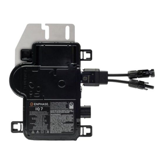
8 mm (5/16") mounting hardware: 9 N m (80 to 85 in-lbs.) • When using UL 2703 mounting hardware, use the manufacturer’s recommended torque value. Horizontal mount DC connector AC connector Vertical mount © 2023 Enphase Energy Inc. All rights reserved. September 2023 IOM-00028-1.0... -
Page 19: Step 4: Create An Installation Map
A. Peel the removable serial number label from each microinverter and affix it to the respective location on the paper installation map. B. Peel the label from the IQ Gateway and any Enphase battery, if installed) and affix it to the installation map. -
Page 20: Step 5: Manage The Cabling
Cable clip Step 6: Connect the microinverters A. Connect the microinverter. Listen for a click as the connectors engage. B. Cover any unused connector with Enphase Sealing Caps. Listen for a click as the connectors engage. WARNING: Risk of electric shock. Risk of fire. -
Page 21: Step 7: Terminate The Unused End Of The Cable
WARNING: The terminator cannot be re- used. If you unscrew the nut, you must discard the terminator. © 2023 Enphase Energy Inc. All rights reserved. September 2023 IOM-00028-1.0... -
Page 22: Step 8: Complete The Installation Of The Junction Box
WARNING: Electrical shock hazard. The DC conductors of this photovoltaic system are ungrounded and may be energized. A. If required, attach the Enphase DC bulkhead adaptors to the microinverters. Ensure they are fully seated. Do not reverse the adaptor connections. -
Page 23: Step 10: Energize The System
You can set the grid profile through the Enphase Installer App, during system registration, or through the Enphase Installer App at any time. You must have an IQ Gateway communications gateway to set or change the grid profile. -
Page 24: Troubleshooting
If a microinverter registers a “DC Resistance Low - Power Off” condition, you can attempt to clear this condition. If the condition does not clear after you perform the following procedure, contact Enphase Support at enphase.com/en-us/support/contact. -
Page 25: Other Faults
Method 1: Clear this error using the Enphase Installer App • Log in to the Enphase Installer App and access the system. • Click the Events tab. The next screen shows a current “DC Resistance Low - Power Off”... -
Page 26: Troubleshoot An Inoperable Microinverter
K. Verify the PV module DC voltage is within the allowable range shown in Specifications. L. Swap DC leads with a known good, adjacent PV module. If, after checking the Enphase Installer Portal periodically (this may take up to 30 minutes), the problem moves to the adjacent module, this indicates that the PV module is not functioning correctly. -
Page 27: Disconnect A Microinverter
4.3 Disconnect a microinverter If problems remain after following the troubleshooting steps listed previously, contact Enphase at enphase.com/en-us/support/contact. If Enphase authorizes a replacement, follow the steps below. To ensure the microinverter is not disconnected from the PV modules under load, follow the disconnection steps in the order shown: A. -
Page 28: Install A Replacement Microinverter
Status LED on the connector side of the microinverter. Use the Enphase Installer App to delete the old microinverter serial number from the IQ Gateway database. In the Enphase Installer App, once connected to the IQ Gateway: a. -
Page 29: Ordering Replacement Parts
Microinverter Communications LED Device Scan button K. Log in to Enphase App to use Enphase App’s Array Builder to add the newly detected microinverter to the virtual array. L. Ship the old microinverter to Enphase using the supplied return shipping label. -
Page 30: Cabling Options
AC module mount • IQ Sealing Caps (female): (Q-SEAL-10) One needed to cover each unused connector on the cabling • IQ Terminator: (Q-TERM-10) Terminator cap for cut cable ends © 2023 Enphase Energy Inc. All rights reserved. September 2023 IOM-00028-1.0... -
Page 31: Technical Data
Apply the following considerations when installing the Enphase IQ7 Series Microinverter system: WARNING: Risk of equipment damage. You must match the DC operating voltage range of the PV module with the allowable input voltage range of the Enphase microinverter. WARNING: Risk of equipment damage. The maximum open circuit voltage of the PV module must not exceed the specified maximum input voltage of the Enphase microinverter. -
Page 32: Specifications
208 VAC (single phase) Arms 1.15 Nominal frequency No enforced DC/AC ratio. See the compatibility calculator at enphase.com/en-us/support/module- compatibility Nominal Voltage Range can be extended if required by the utility. © 2023 Enphase Energy Inc. All rights reserved. September 2023 IOM-00028-1.0... - Page 33 When using UL 2703 mounting hardware, use the manufacturer’s recommended torque value Limits may vary. Refer to local requirements to define the number of microinverters per branch in your area. © 2023 Enphase Energy Inc. All rights reserved. September 2023 IOM-00028-1.0...
- Page 34 Power line communication (PLC) Integrated DC disconnect/ The DC and AC connectors have been evaluated and approved for use as the load-break disconnect required by Integrated AC disconnect NEC 690. © 2023 Enphase Energy Inc. All rights reserved. September 2023 IOM-00028-1.0...
-
Page 35: Iq7Plus-72-2-Us Microinverter Specifications
Overvoltage class AC port AC port backfeed under single fault No enforced DC/AC ratio. See the compatibility calculator at enphase.com/en-us/support/module- compatibility Nominal Voltage Range can be extended if required by the utility. © 2023 Enphase Energy Inc. All rights reserved. September 2023 IOM-00028-1.0... - Page 36 2015 Rule 64-218 Rapid Shutdown of PV Systems, for AC and DC conductors when installed according to manufacturer’s instructions. Limits may vary. Refer to local requirements to define the number of microinverters per branch in your area. © 2023 Enphase Energy Inc. All rights reserved. September 2023 IOM-00028-1.0...
-
Page 37: Iq7X-96-2-Us Microinverter Specifications
Grounding arrays in NEC. Ground fault protection (GFP) is integrated into the class II double-insulated microinverter. Monitoring Enphase Installer Portal monitoring options require an Enphase IQ Gateway. Integrated DC disconnect/ The DC and AC connectors have been evaluated and Integrated AC disconnect approved for use as the load-break disconnect required by NEC 690. - Page 38 Natural convection - no fans Relative humidity range 4% to 100% condensing Limits may vary. Refer to local requirements to define the number of microinverters per branch in your area. © 2023 Enphase Energy Inc. All rights reserved. September 2023 IOM-00028-1.0...
-
Page 39: Iq7A-72-2-Us Microinverter Specifications
The DC circuit meets the requirements for ungrounded PV arrays in NEC. Ground fault protection (GFP) is integrated into the class II double-insulated microinverter. Monitoring Enphase Installer Portal monitoring options require an Enphase IQ Gateway. Integrated DC disconnect/ The DC and AC connectors have been evaluated and... - Page 40 Nominal Voltage Range can be extended if required by the utility. Limits may vary. Refer to local requirements to define the number of microinverters per branch in your area. © 2023 Enphase Energy Inc. All rights reserved. September 2023 IOM-00028-1.0...
- Page 41 The DC circuit meets the requirements for ungrounded PV arrays in NEC. Ground fault protection (GFP) is integrated into the class II double-insulated microinverter. Monitoring Enphase Installer Portal monitoring options require an Enphase IQ Gateway. Integrated DC disconnect/ The DC and AC connectors have been evaluated and approved Integrated AC disconnect for use as the load-break disconnect required by NEC 690.
-
Page 42: Iq Cable Specifications
5.2.6 Enphase connector ratings Enphase connectors on the cable assemblies in the following table have a maximum current of 20 A, a maximum OCPD of 20 A, and a maximum ambient temperature of -40°C to 79°C (-40°F to 174.2°F) and are rated for disconnection under load. -
Page 43: Enphase Installation Map
IQ7/IQ7+/IQ7X/IQ7A Microinverters Installation and Operation Manual 5.3 Enphase installation map © 2023 Enphase Energy Inc. All rights reserved. September 2023 IOM-00028-1.0... -
Page 44: Sample Wiring Diagram
IQ7/IQ7+/IQ7X/IQ7A Microinverters Installation and Operation Manual Sample wiring diagram © 2023 Enphase Energy Inc. All rights reserved. September 2023 IOM-00028-1.0... -
Page 45: Revision History
September 2023 Updated the document to the latest template. © 2023 Enphase Energy. All rights reserved. Enphase, the e and CC logos, IQ, and certain other marks listed at https://enphase.com/trademark-usage-guidelines are trademarks of Enphase Energy, Inc. in the US and other countries.
Need help?
Do you have a question about the IQ7 and is the answer not in the manual?
Questions and answers