enphase IQ 7 Installation And Operation Manual
Microinverters
Hide thumbs
Also See for IQ 7:
- Quick start manual ,
- Installation and operation manual (45 pages) ,
- Quick install manual (5 pages)

Related Manuals for enphase IQ 7


Summary of Contents for enphase IQ 7
- Page 1 INSTALLATION AND OPERATION MANUAL Enphase IQ 7, IQ 7+, IQ 7X, and IQ 7A Microinverters July 08, 2020 141-00044-02...
- Page 2 IQ 7 / IQ 7+ / IQ 7X / IQ 7A Installation and Operation Corporate Headquarters Contact Information Enphase Energy Inc. https://enphase.com/en-us/support/global-contact Other Information Product information is subject to change without notice. All trademarks are recognized as the property of their respective owners.
-
Page 3: Table Of Contents
IQ 7 / IQ 7+ / IQ 7X / IQ 7A Installation and Operation Table of Contents Important Safety Information ............................ 4 Read this First ............................4 Product Labels ............................4 Safety and Advisory Symbols........................4 IQ 7 Series Microinverter Safety Instructions ..................... 4 The Enphase IQ System............................ -
Page 4: Important Safety Information
Double-insulated Safety and Advisory Symbols To reduce the risk of electric shock, and to ensure the safe installation and operation of the Enphase IQ System, the following safety symbols appear throughout this document to indicate dangerous conditions and important safety instructions. - Page 5 IQ 7 / IQ 7+ / IQ 7X / IQ 7A Installation and Operation Do not use Enphase equipment in a manner not specified by the manufacturer. Doing so may cause DANGER: Risk of death or injury to persons, or damage to equipment.
- Page 6 When installing the Enphase Q Cable, secure any loose cable to minimize tripping hazard. When looping the Enphase Q Cable, do not form loops smaller than 4.75” (12 cm) in diameter. NOTES: Provide support for the Enphase Q-Cable every 1.8m (6 feet).
-
Page 7: The Enphase Iq System
The Enphase IQ System The Enphase IQ System includes: • Enphase IQ 7, IQ 7+, IQ 7X and IQ 7A Microinverters. The smart grid ready IQ Series Microinverters convert the DC output of the PV module into grid-compliant AC power. •... -
Page 8: How The Enphase Iq Series Micros Work
Microinverter systems are inherently more reliable than traditional inverters. The distributed nature of a microinverter system ensures that there is no single point of system failure in the PV system. Enphase Microinverters are designed to operate at full power at ambient temperatures as high as 65 C (150 F). -
Page 9: Planning For Microinverter Installation
• The Enphase IQ 7 Microinverter is compatible with 60-cell PV modules. • The IQ 7+ and IQ 7A Microinverters support PV modules with 60 cells / 120-half-cells or 72 cells / 144-half-cells. • The IQ 7X requires a 96-cell PV module. -
Page 10: Branch Circuit Capacity
Select the correct wire size based on the distance from the beginning of the microinverter AC branch circuit to the breaker in the load center. Enphase recommends a voltage rise total of less than 2% for the sections from the microinverter AC branch circuit to the breaker in the load center. -
Page 11: Parts And Tools Required
IQ 7 / IQ 7+ / IQ 7X / IQ 7A Installation and Operation Parts and Tools Required In addition to the microinverters, PV modules, and racking, you will need the following: Enphase Equipment • Enphase Envoy-S gateway required to monitor solar production. For installation information, refer to the Enphase Envoy-S Installation and Operations Manual. -
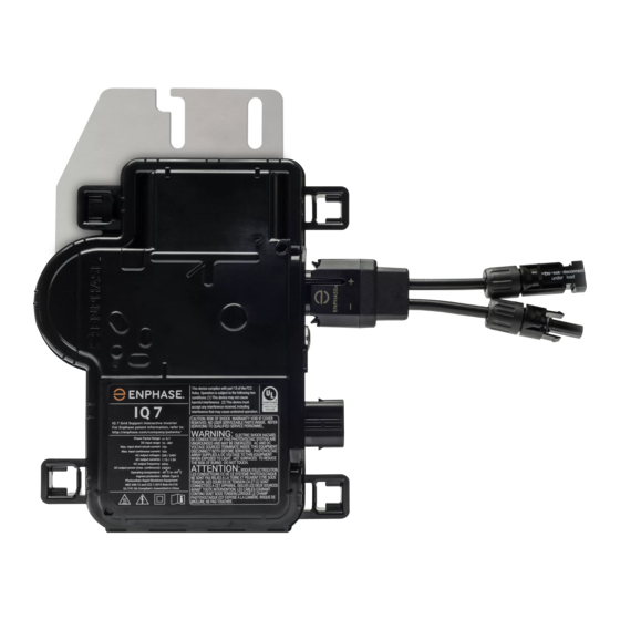
Page 12: Enphase Microinverter Installation
IQ 7 / IQ 7+ / IQ 7X / IQ 7A Installation and Operation Enphase Microinverter Installation Installing the Enphase IQ Series Micros involves several key steps. Each step listed here is detailed in the following pages. Step 1: Position the Enphase Q Cable... -
Page 13: Step 1: Position The Enphase Q Cable
IQ 7 / IQ 7+ / IQ 7X / IQ 7A Installation and Operation Step 1: Position the Enphase Q Cable A. Plan each cable segment to allow drop connectors on the Enphase Q Cable to align with each PV module. Allow extra length for slack, cable turns, and any obstructions. -
Page 14: Step 3: Mount The Microinverters
IQ 7 / IQ 7+ / IQ 7X / IQ 7A Installation and Operation Step 3: Mount the Microinverters A. If the Enphase DC bulkhead connectors are not already attached to the microinverters, attach them now. Make sure they are fully seated. -
Page 15: Step 4: Create An Installation Map
Each Enphase Microinverter, Envoy, and Battery have a removable serial number label. Build the installation map by peeling the serial number labels from the microinverter mounting plates and placing the labels on the map. You will also place the Enphase Envoy-S and IQ Battery serial number on the map after installation. -
Page 16: Step 5: Manage The Cabling
IQ 7 / IQ 7+ / IQ 7X / IQ 7A Installation and Operation Step 5: Manage the Cabling A. Use cable clips or tie wraps to attach the cable to the racking. Leave no more than 1.8 m between cable clips or tie wraps. -
Page 17: Step 7: Terminate The Unused End Of The Cable
IQ 7 / IQ 7+ / IQ 7X / IQ 7A Installation and Operation Step 7: Terminate the Unused End of the Cable Terminate the unused end of the Enphase Q Cable as follows: Single-phase Q Cable Three-phase Q Cable 13mm A. -
Page 18: Step 8: Complete Installation Of The Junction Box
IQ 7 / IQ 7+ / IQ 7X / IQ 7A Installation and Operation Step 8: Complete Installation of the Junction Box A. Connect the Enphase Q Cable into the junction box. B. Refer to the wiring diagrams on page 39 for more information. Q Cable uses the following... -
Page 19: Step 10: Energize The System
Enlighten, during system registration, or through Installer Toolkit at any time. You must have an Enphase Envoy to set or change the grid profile. For more information on setting or changing the grid profile, refer to the Enphase Envoy- S Installation and Operation Manual at enphase.com/support. -
Page 20: Troubleshooting
IQ 7 / IQ 7+ / IQ 7X / IQ 7A Installation and Operation Troubleshooting Follow all the safety measures described throughout this manual. Qualified personnel can use the following troubleshooting steps if the PV system does not operate correctly. -
Page 21: Other Faults
The app then indicates that a clear message was sent. Other Faults All other faults are reported to the Envoy. Refer to the Enphase Envoy-S Installation and Operation Manual at enphase.com/support for troubleshooting procedures. -
Page 22: Troubleshoot An Inoperable Microinverter
IQ 7 / IQ 7+ / IQ 7X / IQ 7A Installation and Operation Troubleshoot an Inoperable Microinverter To troubleshoot an inoperable microinverter, follow the steps in the order shown. WARNING: Risk of electric shock. Always de-energize the AC branch circuit before servicing. -
Page 23: Disconnect A Microinverter
IQ 7 / IQ 7+ / IQ 7X / IQ 7A Installation and Operation Disconnect a Microinverter If problems remain after following the troubleshooting steps listed previously, contact Customer Support at https://enphase.com/en-us/support/global-contact. If Enphase authorizes a replacement, follow the steps below. To ensure the microinverter is not disconnected from the PV modules under load, follow the disconnection steps in the order shown: A. -
Page 24: Install A Replacement Microinverter
IQ 7 / IQ 7+ / IQ 7X / IQ 7A Installation and Operation Install a Replacement Microinverter A. When the replacement microinverter is available, verify that the AC branch circuit breaker is de-energized. B. Mount the microinverter bracket side up and under the PV module, away from rain and sun. -
Page 25: Ordering Replacement Parts
IQ 7 / IQ 7+ / IQ 7X / IQ 7A Installation and Operation J. Add the new microinverter serial number to the Envoy database by initiating a device scan using one of the following methods: a. Method 1: Initiate a scan using the Installer Toolkit mobile app •... -
Page 26: Enphase Q Cable Planning And Ordering
IQ 7 / IQ 7+ / IQ 7X / IQ 7A Installation and Operation Enphase Q Cable Planning and Ordering The Enphase Q Cable is a continuous length of double insulated, outdoor-rated cable with integrated connectors for microinverters. These connectors are preinstalled along the Q Cable at intervals to accommodate varying PV module widths. -
Page 27: Technical Data
Harmonic injection (soon to be replaced by VAR injection) PQ Capability Curve If needed, Enphase IQ 7 Series Microinverters have the capability to absorb or inject reactive power, provided that current and voltage ratings are not exceeded. Below is an active power (P) capabilities curve relative to reactive power (Q) related to the power rating in the operating voltage range for Enphase IQ 7 Series. -
Page 28: Specifications
IQ 7 / IQ 7+ / IQ 7X / IQ 7A Installation and Operation Specifications The following tables list specifications for the various IQ 7 Series models and for the Q Cable. IQ7-60-2-INT Microinverter Specifications Enphase IQ7-60-2-INT Microinverter Parameters Topic... - Page 29 IQ 7 / IQ 7+ / IQ 7X / IQ 7A Installation and Operation Enphase IQ7-60-2-INT Microinverter Parameters Miscellaneous Parameters Maximum microinverters per 20A (max) AC branch circuit 16 (single-phase) 230 VAC 48 (multiphase) EN 50530 (EU) weighted efficiency 230 VAC (single phase) 96.5...
-
Page 30: Iq7Plus-72-2-Int Microinverter Specifications
IQ 7 / IQ 7+ / IQ 7X / IQ 7A Installation and Operation IQ7PLUS-72-2-INT Microinverter Specifications IQ7PLUS-72-2-INT Microinverter Parameters Topic Unit Typical DC Parameters Commonly used module pairings 235 W - 440+ W Peak power tracking voltage Operating range... - Page 31 IQ 7 / IQ 7+ / IQ 7X / IQ 7A Installation and Operation IQ7PLUS-72-2-INT Microinverter Parameters Miscellaneous Parameters Maximum microinverters per 20A (max) AC branch circuit 13 (single-phase) 230 VAC (single phase) 39 (multiphase) EN 50530 (EU) weighted efficiency 230 VAC (single phase) 96.5...
-
Page 32: Iq7A-72-2-Int Microinverter Specifications
IQ 7 / IQ 7+ / IQ 7X / IQ 7A Installation and Operation IQ7A-72-2-INT Microinverter Specifications IQ7A-72-2-INT Microinverter Parameters Topic Unit Typical DC Parameters Commonly used module pairings 295 W - 460+ W Peak power tracking voltage Operating range... - Page 33 IQ 7 / IQ 7+ / IQ 7X / IQ 7A Installation and Operation IQ7A-72-2-INT Microinverter Parameters Miscellaneous Parameters Maximum microinverters per 20A (max) AC 11 (single-phase) branch circuit – 230 VAC 39 (multiphase, requires 25 A OCPD) EN 50530 (EU) weighted efficiency 230 VAC (single phase) 96.5...
-
Page 34: Iq7X-96-2-Int Microinverter Specifications
IQ 7 / IQ 7+ / IQ 7X / IQ 7A Installation and Operation IQ7X-96-2-INT Microinverter Specifications IQ7X-96-2-INT Microinverter Parameters Topic Unit Typical DC Parameters Commonly used module pairings 320 W - 460+ W Peak power tracking voltage Operating range 79.5... - Page 35 IQ 7 / IQ 7+ / IQ 7X / IQ 7A Installation and Operation IQ7X-96-2-INT Microinverter Parameters Miscellaneous Parameters Maximum microinverters per 20A (max) AC branch circuit 12 (single-phase) 230 VAC (single phase) 36 (multiphase) EN 50530 (EU) weighted efficiency 230 VAC (single phase) 96.5...
-
Page 36: Q Cable Specifications
IQ 7 / IQ 7+ / IQ 7X / IQ 7A Installation and Operation Q Cable Specifications H07BQ-F Cable IEC60227 Cable Specification (without “-A” designation (with “-A” designation) 450/750V Voltage rating 300/500V (connector rating up to 250V) Voltage withstand test (kV/1min) AC 3.0... -
Page 37: Enphase Installation Map
IQ 7 / IQ 7+ / IQ 7X / IQ 7A Installation and Operation Enphase Installation Map © 2020 Enphase Energy Inc. All rights reserved. 141-00044-02... -
Page 38: Sample Wiring Diagram - Single-Phase
IQ 7 / IQ 7+ / IQ 7X / IQ 7A Installation and Operation Sample Wiring Diagram – single-phase: © 2020 Enphase Energy Inc. All rights reserved. 141-00044-02... -
Page 39: Sample Wiring Diagram - Multiphase
IQ 7 / IQ 7+ / IQ 7X / IQ 7A Installation and Operation Sample Wiring Diagram – multiphase: © 2020 Enphase Energy Inc. All rights reserved. 141-00044-02...
Need help?
Do you have a question about the IQ 7 and is the answer not in the manual?
Questions and answers