enphase IQ 7 Quick Install Manual
Microinverters
Hide thumbs
Also See for IQ 7:
- Quick start manual ,
- Installation and operation manual (45 pages) ,
- Installation and operation manual (39 pages)
Advertisement
Q U I C K I N S T A L L G U I D E
Installing Enphase IQ 7, IQ 7+ and IQ 7X Microinverters
To install Enphase IQ Series Microinverters, read and follow all warnings and instructions in this guide and in the Enphase IQ 7 and IQ 7+ Microinverter
Installation and Operation Manual at: enphase.com/support. Safety warnings are listed on the back of this guide.
The Enphase Microinverter models listed in this guide do not require grounding electrode conductors (GEC), equipment grounding conductors (EGC), or
grounded conductor (neutral). The microinverter has a Class II double-insulated rating, which includes ground fault protection (GFP). To support GFP, use
only PV modules equipped with DC cables labeled PV Wire or PV Cable.
IMPORTANT: Enphase IQ Series Microinverters require the Q Cable and are not compatible with previous Enphase cabling. An IQ Envoy is required to
monitor performance of the IQ
PREPARATION
A ) Download the Enphase Installer Toolkit mobile app and
open it to log in to your Enlighten account. With this app,
you can scan microinverter serial numbers and connect
to the Enphase IQ Envoy to track system installation
progress. To download, go to
scan the QR code at right.
B ) Refer to the following table and check PV module electrical compati-
bility at: enphase.com/en-us/support/module-compatibility.
Model
DC connector
IQ7-60-2-US
MC-4 locking type
IQ7PLUS-72-2-US
MC-4 locking type
IQ7X-96-2-US
MC-4 locking type
C ) In addition to the Enphase Microinverters, PV modules and racking,
you will need these Enphase items:
Enphase IQ Envoy (model ENV-IQ-AM1-240) communications
•
gateway or IQ Combiner+ (model X-IQ-AM1-240-2): required to
monitor solar production
Tie wraps or cable clips (Q-CLIP-100)
•
Enphase Sealing Caps (Q-SEAL-10): for any unused connectors on
•
the Enphase Q Cable
Enphase Terminator (Q-TERM-10): one needed at the end of each AC
•
cable segment
Enphase Disconnect Tool (Q-DISC-10)
•
Enphase Q Cable:
•
Cable model Connector
spacing*
Q-12-10-240
1.3m
Q-12-17-240
2.0m
Q-12-20-200
2.3m
*Allows for 30 cm of cable slack
Microinverters.
The Q Accessories work only with Enphase IQ Series Microinverters.
enphase.com/toolkit
or
PV module cell count
Pair only with 60-cell modules.
Pair with 60- or 72-cell modules.
Pair only with 96-cell modules.
PV module
Connectors
orientation
per box
Portrait (all)
Landscape (60- and 96-cell)
Landscape (72-cell)
.
junction box
D ) Check that you have these other items:
AC junction box.
•
Tools: screwdrivers, wire cutter, voltmeter, torque wrench, sockets,
•
and wrenches for mounting hardware
E ) Protect your system with lightning and/or surge suppression devices. It
is also important to have insurance that protects against lightning and
electrical surges.
F ) Plan your AC branch circuits to meet the following limits for maximum
number of microinverters per branch when protected with a 20-amp
over-current protection device (OCPD).
Maximum*
IQ Micros
per AC
branch
circuit
* Limits may vary. Refer to local requirements to define the number of
microinverters per branch in your area.
G ) Size the AC wire gauge to account for voltage rise. Select the correct
wire size based on the distance from the beginning of the Enphase Q
Cable to the breaker in the load center. Design for a voltage rise total of
less than 2% for the sections from the Enphase Q Cable to the breaker
in the load center. Refer to the Voltage Rise Technical Brief at
enphase.com/support
Best practice: Center-feed the branch circuit to minimize voltage rise in
a fully-populated branch.
240
240
200
DC connector
Tie wraps or
cable clips
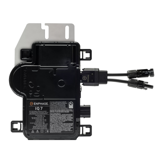
Enphase
IQ Series Micro
IQ 7 Micros
IQ 7+ Micros
(240V single phase)
(240V single phase)
16
13
IQ 7 Micros
IQ 7+ Micros
(208V single phase)
(208V single phase)
13
11
for more information.
Enphase
Q Cable
AC connector
IQ 7X Micros
(240V single phase)
12
IQ 7X Micros
(208V single phase)
10
terminator
Enphase
disconnect
tool
Advertisement
Table of Contents

Related Manuals for enphase IQ 7


Summary of Contents for enphase IQ 7
- Page 1 Installing Enphase IQ 7, IQ 7+ and IQ 7X Microinverters To install Enphase IQ Series Microinverters, read and follow all warnings and instructions in this guide and in the Enphase IQ 7 and IQ 7+ Microinverter Installation and Operation Manual at: enphase.com/support. Safety warnings are listed on the back of this guide.
-
Page 2: Installation
Position the Enphase Q Cable A ) Peel the removable serial number label from each microinverter A ) Plan each cable segment to allow connectors on the Enphase Q Cable and affix it to the respective location on the paper installation map. - Page 3 • Enphase Connector Rating Enphase Connectors on the cable assemblies in the following table have a maximum current of 20 A, a maximum OCPD of 20 A, and maximum ambient temperature of -40° to +79° C (-40° to +174.2° F) and are rated for disconnection under load.
-
Page 4: Pv Rapid Shutdown Equipment (Pvrse)
Part 1 and NFPA 70 (NEC). tains important instructions to follow during installation You must cover any unused connector with a of the Enphase IQ 7 and IQ 7+ Microinverter. ✓ NOTE: The AC and DC connectors on the sealing cap.
Need help?
Do you have a question about the IQ 7 and is the answer not in the manual?
Questions and answers