CARDIOSTRONG EX80 Plus Assembly And Operating Instructions Manual
Elliptical cross trainer
For more information, please visit cardiostrong.com, sport-tiedje.com

Related Manuals for CARDIOSTRONG EX80 Plus


Summary of Contents for CARDIOSTRONG EX80 Plus
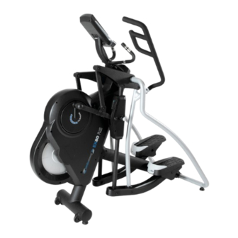
- Page 1 Assembly and operating instructions CSTEX80PLUS.02.04 Art. No. CST-EX80-2-Plus Elliptical cross trainer EX80 Plus ...
- Page 2 EX80 Plus...
- Page 3 Dear Customer, Thank you for deciding for a high-quality training equipment of the brand cardiostrong®, the brand that makes athlete‘s hearts beat faster. cardiostrong® offers a wide range of home fitness equipment like elliptical cross trainers, ergometers, treadmills and rowing machines. cardiostrong® equipment is the optimal equipment for all those who want to train at home independent of goals and fitness level.
-
Page 4: Table Of Contents
CONTENTS GENERAL INFORMATION 1.1 Technical data 1.2 Personal safety 1.3 Electrical safety 1.4 Set-up place ASSEMBLY INSTRUCTIONS, MAINTENANCE AND CARE 2.1 General instructions 2.2 Faults and Troubleshooting 2.3 Maintenance and service calendar ASSEMBLY 3.1 Package contents 3.2 Assembly instructions OPERATING INSTRUCTIONS 4.1 Console display 4.2 Button functions 4.3 Turning on and setting the equipment... -
Page 5: General Information
GENERAL INFORMATION Technical data LCD display of speed in km/h training time in min training distance in km cadence (rotations per minute) calories burnt in kcal heart rate (when using the hand sensors or a chest strap) Watt resistance level Resistance system: electronic magnetic brake system Resistance level:... -
Page 6: Personal Safety
Personal safety Before you start using the equipment, you should consult your physician that this type of exercise is suitable for you from a health perspective. Particularly affected are persons who: have a hereditary disposition to high blood pressure or heart disease, are over the age of 45, smoke, have high cholesterol values, are overweight and/or have not exercised regularly in the past year. -
Page 7: Electrical Safety
Electrical safety The equipment requires a 220 - 230V / 50 Hertz mains power supply. The equipment should be connected directly to a grounded plug socket only by means of the power cable supplied. The use of multi-socket adapters or similar is not recommended. Extension leads must comply with local electrical safety guidelines. -
Page 8: Assembly Instructions, Maintenance And Care
You should therefore immediately replace damaged or worn components. Please contact your contract partner in such a case. The equipment should no longer be used until it has been repaired. When needed, only use original cardiostrong® spare parts. Check the tightness of all screw connections once a month. -
Page 9: Faults And Troubleshooting
Faults and Troubleshooting The equipment runs through regular quality controls during production. Nevertheless, errors or malfunctions on the equipment may occur. Individual parts are often the cause of faults and replacement is usually sufficient. Please use the following overview to see the six most common errors and how to repair them. -
Page 10: Assembly
ASSEMBLY Package contents The package contains the parts represented in the illustration, including a power cable with mains plug. If one of the illustrated parts is missing, please contact your contract partner. EX80 Plus... -
Page 11: Assembly Instructions
Assembly instructions Before starting assembly, look carefully through the individual assembly steps shown and assemble the equipment in the order indicated. Caution while unpacking: Place box flat on the ground, remove cover. Unpack handles, side supporting bars, pedal bars and operating instructions. - Page 12 Step 1: Assembly of the console mast (1) Remove the two pre-mounted screws (F5) from the main frame (A) and two screws (F5) from the console mast (F1). (2) Mount the console mast (F1) on the main frame (A) with the previously removed screws (F5). Note: Tighten all four screws (F5) before you continue with step 2.
- Page 13 Step 2: Assembly of the right connecting tube (1) See view A: Mount right connecting tube (C2) on the main frame (A). (2) Tighten the tube with screws (J8) M8 x 20 on the frame. (3) See view B: Tighten tube with two screws (J2) M8x60 and clamp (F2) on the bottom of the frame. Note: First completely View A tighten screws (J8 and...
- Page 14 Step 3: Assembly of the left supporting foot and joint cover (1) Mount the left connecting tube (C1) with the main frame (A) on the top with the screw (J8) and on the bottom with the two screws (J2) with the clamp (F2) - just like the right tube (C2) in figure 2. (2) Now all screws (J8, J2) of steps 2 and 3 can be tightened.
- Page 15 Step 4: Assembly of the pedal supporting tube (1) See view C: Connect right pedal supporting tube (B2) with the main frame (A) and tighten with nut (J4), washer (J9) and screw (J3). (2) See view D: Tighten nut (J4), washer(J9) and screw (J3) after the screw (J5), washer (J9) and nut (J4) are tight.
- Page 16 Step 5: Assembly of the handles (1) Remove the six pre-mounted screws (J10 and J11) from the left handle (E1). (2) See view F: Mount left handle (E1) on main frame (A) and tighten all screws (J10 and J11) with two 6mm Allen wrenches.
- Page 17 Step 6: Assembly of the console supporting tube and the bottle holder (1) Connect cable (D1) from the console supporting tube (D) with cables (A1) on the main frame (A). (2) See view G: Mount the console supporting tube (D) on the main frame (A) with two screws (J1) and the two pre-mounted screws (J1).
- Page 18 Step 7: Assembly of the console (1) Remove four screws (G1) on the back of the console (G). (2) Connect the console cable (D1) and pulse cable (D3) with the fitting pieces on the console (G). Make sure that the cables are connected correctly.
- Page 19 Step 8: Transport In order to move the equipment, lift on both sides of the connecting tubes until the transport wheels touch the ground. Then move the equipment to the desired place. Now slowly and carefully lower the equipment to the floor. If necessary, adjust the leveling feet below the rear base of the equipment. WARNING: Do not lift the equipment alone! For safety reasons, at least with two people.
- Page 20 Step 9: Power cable Insert power cable in the plug on the equipment before the equipment is connected to the outlet. Note: The overload switch serves as a protective mechanism. It is triggered if the equipment has an electrical overload. Turn off the power switch and then back on in order to restart the equipment. ...
- Page 21 Step 10: Adjust stride lengths (1) There are five different stride lengths (45 cm (18“), 50 cm (20“), 55 cm (22“), 60 cm (24“), 65 cm (26“), which are illustrated in the LED window. (2) Loosen and remove the pin in order to set the desired stride length. (3) Once the stride length has been selected, tighten the pin again.
-
Page 22: Operating Instructions
OPERATING INSTRUCTIONS Console display EX80 Plus... - Page 23 Time 0:00 - 99:00 minutes Speed 0.0 - 99.9 km/h RPM (cadence; rotations per minute) 0 - 999 RPM Distance 0.0 - 99.9 km Calories 0 - 990 Cal Gender Male/Female (m/f ) Pulse (heart rate; heart beats per minute) 30 - 230 BPM Heart rate symbol On/off - blinking...
-
Page 24: Button Functions
Button functions TURNING KNOB With this button, you can change the RIGHT settings or increase the resistance. With this button, you can change the TURNING KNOB LEFT settings or lower the resistance. TURNING KNOB With this button, you can confirm all ENTER settings. -
Page 25: Turning On And Setting The Equipment
Turning on and setting the equipment Connect the power cable with the console and press the RESET button for two seconds. An alarm will sound for two seconds and the specification 78.0 will be displayed in the lower left window (see figure 1 and 2). -
Page 26: Programs
Programs Once you have entered all values, you can select one of the five program categories with the control knob (see figure 9-13). The equipment has a total of 19 programs and a fitness test. • Manual (manual training): 1 •... -
Page 27: Man. - Manual Program
4.4.1 MAN. - Manual program After you have selected the manual program and confirmed with ENTER, you can enter the values for the intensity level (1-16), time, distance, calories and pulse with the control knob. If you enter a target value for time, distance and calories, the training will stop automatically once you have achieved one of these target values. - Page 28 Profiles from preset training programs: Procedure for setting the preset training programs: Set program mode Select program P1-P12 Specification of the training time Turn left Press Turn left Press Turn left Press Press or right Enter or right Enter or right Enter Start/Stop ...
-
Page 29: User - User Defined Program
4.4.3 USER - User defined program Once you have selected the program, you can manually set each of the 20 sections of the profile with the control knob. For each section, select an intensity level between 1-16, confirm the setting with ENTER and continue with the next section. -
Page 30: H.r.c. - Heart Rate Oriented Programs
4.4.4 H.R.C. - Heart rate oriented programs After you have selected the program, you can enter the desired target heart rate. Either select one of the three target heart rates (55%, 75% or 90% of your maximum heart rate) or select “TAG” and enter a target heart rate. -
Page 31: Watt - Watt Controlled Program
4.4.5 WATT - Watt controlled program If you selected the program, use the control knob to enter the desired watt value that you would like to train with between 10 and 350 Watt. The preset value is 120 Watt. Confirm the setting with the ENTER button. -
Page 32: Recovery - Fitness Test
4.4.6 RECOVERY - Fitness test With this button, you can measure your recovery heart rate after training. After training, press the RECOVERY button and hold the hand pulse sensors if you are not wearing a chest strap. After this, a one-minute countdown will start. -
Page 33: Heart Rate Measuring
Heart-rate measuring Pulse measuring via hand sensors The hand sensors integrated in the handles allow you to determine your heart rate. You can measure your heart rate by lightly grasping the sensors with both hands at the same time. Blood pressure changes occur due to the heartbeat. - Page 34 Fat burning (weight management): The main goal here is to burn deposits of fat. In order to achieve this training goal, a low training intensity (approximately 55% of the maximum heart rate) and a longer training period are required. Cardiovascular training (cardio training): The primary goal is to increase stamina and fitness through an improved provision of oxygen through the cardiovascular system.
-
Page 35: Warranty Information
WARRANTY INFORMATION cardiostrong‘s fitness equipment is subject to strict quality controls. However, if a fitness equipment purchased from us does not work perfectly, we take it very seriously and ask you to contact our customer service as indicated. We are happy to help you by phone via our service hotline. - Page 36 Warranty conditions For the warranty to be valid, the following steps must be taken: Please contact our customer service by email or phone. If the product under warranty has to be sent in for repair, the seller bears costs. After expiry of the warranty, the buyer bears the costs of transport and insurance.
-
Page 37: Disposal
DISPOSAL At the end of its operational life, this equipment cannot be disposed of in normal household waste. Instead, it must be disposed of via an electricals recycling centre. Further information can be obtained from your local authority‘s recycling service. The materials can be recycled as per their symbols. -
Page 38: Ordering Spare Parts
10:00 - 17:00 Serial number and model name Before assembling your equipment, find the serial number on the white sticker and enter it in the appropriate space. Serial number: Brand / category: Model name: cardiostrong elliptical cross trainer EX80-2-Plus EX80 Plus... -
Page 39: Parts List
Parts list Description Qty. Description Qty. Main Frame Crank Sensor Wire Flat Key Connection Slice Screw Motor Turing Plate A3-1 Screw Pressing Pipe Dc Wire Bearing 6003Zz C Lip Sensor Wire Nut M12 Sensor Wire Housing Washer M12 Screw Axle Screw M8 X 45 Bearing 6001Mrb Nut M8... - Page 40 Description Qty. Description Qty. Washer M8 Small Chain Cover ( R ) Bolt M12 X 53 Screw Washer M12 Screw Nut M12 Pedal Supporting Tube ( L ) Led Display Pedal Supporting Tube ( R ) Bearing Sleeve Pedal Housing ( L ) Bush Pedal Housing ( R ) Bearing 6201Zz...
- Page 41 Description Qty. Description Qty. Bush Screw M3 X 8 Bearing 6003Zz End Cap Bush Handle Bar ( L ) Screw Handle Bar ( R ) Pedal Reinforcement Strip Central Supporting Tube Screw Iron Bracket Side Connecting Tube ( L ) Central Supporting Tube Cover ( L ) Side Connecting Tube ( R ) Central Supporting Tube Cover ( R )
-
Page 42: Exploded Drawing
Exploded drawing EX80 Plus... - Page 44 DISCLAIMER ©2010 cardiostrong® is a registered brand of the company Sport- Tiedje GmbH. All rights reserved. Any use of this trademark without the explicit written permission of Sport- Tiedje is prohibited. Product and manual are subject to change. Technical data can be changed without advance notice.
- Page 46 Elliptical cross trainer EX80 Plus ...
Need help?
Do you have a question about the EX80 Plus and is the answer not in the manual?
Questions and answers