CARDIOSTRONG EX90 Plus Assembly And Operating Instructions Manual
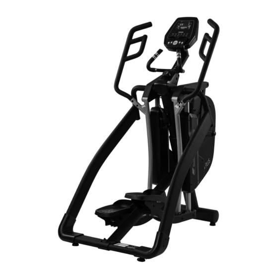
Elliptical cross trainer
For more information, please visit cardiostrong.com, sport-tiedje.com

Related Manuals for CARDIOSTRONG EX90 Plus


Summary of Contents for CARDIOSTRONG EX90 Plus
- Page 1 Assembly and Operating Instructions CSTEX90PLUS.01.04 Art. No. CST-EX90-PLUS Elliptical cross trainer EX90 Plus ...
- Page 2 EX90 PLUS ...
-
Page 3: Table Of Contents
Content GENERAL INFORMATION Technical Data Personal Safety Electrical Safety Set-Up Place ASSEMBLY General Instructions Scope of Delivery Assembly OPERATING INSTRUCTIONS Console Display Turning On and Setting the Equipment Programs 3.3.1 Quick Start and Manual 3.3.2 PROG - Pre-set programs 3.3.3 H.R.C. - Heart rate controlled programs 3.3.4 H.R.C. - Page 4 ORDERING SPARE PARTS Serial Number and Model Name Parts List Exploded Drawing WARRANTY CONTACT EX90 PLUS ...
- Page 5 With cardiostrong® fitness equipment, the focus is on what sport is all about: maximum performance! Therefore, the equipment is developed in close consultation with athletes and sports scientists.
- Page 6 ABOUT THIS MANUAL Please carefully read the entire manual before installation and first use. The manual will help you to quickly set up the system and explains how to safely use it. Make sure that all persons exercising with the equipment (especially children and persons with physical, sensory, mental or motor disabilities) are informed about this manual and its contents in advance.
-
Page 7: General Information
GENERAL INFORMATION Technical Data LCD display of speed in km/h training time in min training distance in km cadence (rotations per minute) calories burnt in kcal heart rate (when using the hand sensors or a chest strap) Watt resistance level Resistance system: electronic magnetic brake system Resistance level: Watt:... -
Page 8: Personal Safety
Personal Safety ⚠ DANGER Before you start using the equipment, you should consult your physician that this type of exercise is suitable for you from a health perspective. Particularly affected are persons who: have a hereditary disposition to high blood pressure or heart disease, are over the age of 45, smoke, have high cholesterol values, are overweight and/or have not exercised regularly in the past year. -
Page 9: Electrical Safety
Electrical Safety ⚠ DANGER In order to reduce the risk of an electric shock, always unplug the equipment from the mains socket immediately after your workout, before assembly or dismantling, and before maintenance or cleaning. Do not pull on the cable. ⚠... -
Page 10: Set-Up Place
Set-Up Place ⚠ WARNING Do not place the equipment in main corridors or escape routes. CAUTION ⚠ Choose a location in which to place the equipment such that there is enough free space/ clearance to the front, the rear and to the sides of the equipment. Make sure that you leave at least 30 cm on each side of the equipment and at least 15 cm in front of and behind the equipment as a training zone. -
Page 11: Assembly
ASSEMBLY General Instructions ⚠ DANGER Do not leave any tools, packaging materials such as foils or small parts lying around, as otherwise there is a danger of suffocation for children. Keep children away from the equipment during assembly. ⚠ WARNING Pay attention to the instructions attached to the equipment in order to reduce the risk of injuries. -
Page 12: Scope Of Delivery
Scope of Delivery The scope of delivery consist of the following parts. At the beginning, check whether all parts and tools belonging to the device are included in the scope of delivery and whether damage has occurred. In the event of complaints, the contractual partner must be contacted directly. ⚠... - Page 13 Screws M4x6 Screws M4x16 Screws M8x55 Washers M8 Screws M8x20 Screws M12x73 Washers M12 Screws M12x109 Screws M8x16 Nuts M12 Screws M5...
-
Page 14: Assembly
Assembly Before assembly, take a close look at the individual assembly steps shown and carry out the assembly in the order given. NOTICE First loosely screw all parts together and check that they fit properly. Tighten the screws using the tool only when you are instructed to do so. Step 1: Unpacking Place box flat on the ground, remove cover. - Page 15 Step 2: Assembly of the main mast (F1) Loosen two screws (F5) from the main frame (A) and two screws from the main mast (F1). Connect the main mast (F1) with the main frame (A) with the previously loosened four screws (J1). NOTICE Before you continue with step 3 of the assembly, make sure that the four screws...
- Page 16 Step 4: Assembly of the right side bar (C2) Mount the right side bar (C2) on the main frame (A) with a screw (J8) on top (figure A) and two screws (J5) including washers (J5) with the bracket (F2) on the bottom (figure B). ࣑...
- Page 17 Step 5: Assembly of the left side bar (C1) and covers Connect the left side bar (C1) on the main frame (A) with a screw (J6) on top and two screws (J2) and the bracket (F2) on the bottom. Now you can tighten all of the screws from the previous steps (J6, J4).
- Page 18 Step 7: Assembly of the handles Loosen the six pre-mounted screws (J12 and J11) from the left handle (E1). Connect the left handle (E1) with the main frame (A) by tightening all screws (J12 and J11) with two 6mm Allen keys; see figure F. Repeat the process for the right handle (E2).
- Page 19 Step 9: Assembly of the console and setting the supporting feet Loosen the four pre-mounted screws (G1) from the console (G). Connect the console cables (D1& D3) and the heart rate cable (D4) from the console mast with the console. NOTICE Make sure that the cables are properly connected with each other.
- Page 20 Step 11: Function buttons to adjust the stride length: There is a button on the left and right small handles of the console mast. The left button has the following function: The fine, infinitely variable reduction of the current stride length. The right button has the following function: The fine, infinitely variable increase of the current stride length.
- Page 21 Step 12: Setting the stride length via the incline motor Corresponding to personal requirements, the stride length, as shown on the LED display, can be set or changed to 18”, 20”, 22”, 24” or 26”. There are five quick selection buttons to set the stride length. Press one of the 18”...
- Page 22 Step 13: Alignment of the feet If the floor is uneven, you can stabilize the equipment by turning the two setting screws under the main frame. Lift the equipment on the desired side and rotate the setting screws under the main frame. Rotate the screws clockwise in order to remove them and to raise the equipment.
-
Page 23: Operating Instructions
OPERATING INSTRUCTIONS NOTICE Familiarise yourself with all the functions and setting options of the device before starting training. Have the proper use of this product explained to you by a specialist. Console Display Time 0:00 - 99:00 minutes Speed 0.0 - 99.9 km/h 0 - 999 RPM (cadence;... - Page 24 Programs P1 - P12 User data U1 - U4 Watt/load (output/resistance) 0 - 999 Watt; Watt control: 10 - 350 Watt Level 1 - 16 55 / 75 / 90% of the max. heart rate; manual target rate H.R.C. (heart rate control) (TAG) 1 - 99 years Height...
-
Page 25: Turning On And Setting The Equipment
Turning On and Setting the Equipment NOTICE If the user stops pedaling for more than four minutes, the console will change into the energy saving mode. All settings and training data will be saved until the next training is started. Connect the power cable and the console will turn on with a long beep and all segments from the LCD display will light up for two seconds. -
Page 26: Prog - Pre-Set Programs
3.3.2 PROG - Pre-set programs In the stop mode, the user can press the P1-P12 buttons to get to the selected program quickly. Before training in the program mode, the user can set a target time (TIME). Press UP or DOWN in order to select a program profile and press ENTER/MODE to confirm. The level can be changed during training by pressing UP or DOWN. -
Page 27: H.r.c. - Heart Rate Controlled Programs
3.3.3 H.R.C. - Heart rate controlled programs WARNING ⚠ Your training equipment is not a medical device. The heart rate measurement of this equipment may be inaccurate. Various factors can affect the accuracy of the heart rate measurement. The heart rate measurement serves only as a training aid. Before heart rate controlled training, the user can select 55%, 75% or 90% of the target heart rate. -
Page 28: Storage And Transport
STORAGE AND TRANSPORT General Instructions ⚠ WARNING The storage location should be chosen so that improper use by third parties or children can be prevented. If your equipment does not have transportation wheels, the equipment must be disassembled before transportation. ࣑... -
Page 29: Troubleshooting, Care And Maintenance
TROUBLESHOOTING, CARE AND MAINTENANCE General Instructions ⚠ WARNING Do not make any improper changes to the equipment. CAUTION ⚠ Damaged or worn components may affect your safety and the life of the equipment. Therefore, immediately replace damaged or worn components. In such a case, contact the contract partner. -
Page 30: Maintenance And Inspection Calendar
Eliminate sources of interference (e.g. Sources of interference in mobile phone, WLAN, lawn mower the room and vacuum cleaner robot, etc..) unsuitable chest strap Use a suitable chest strap (see RECOMMENDED ACCESSORIES). Wrong position of chest No pulse display Reposition chest strap... -
Page 31: Recommended Accessories
RECOMMENDED ACCESSORIES To make your training experience even more efficient and pleasant, we recommend that you add suiting accessories to your fitness equipment. This could be a floor mat, for example, which makes your fitness equipment stand more securely and also protects the floor from falling sweat, but it could also be additional handrails on some crosstrainers or silicone spray to keep moving parts in good shape. - Page 32 It's located on a white sticker. The exact position of this sticker is shown in the following illustration. Enter the serial number in the appropriate field. Serial number: Brand / Category: cardiostrong / crosstrainer Model Name: EX90 Plus Article Number: CST-EX90-PLUS EX90 PLUS ...
- Page 33 Parts List Name Qty. Specification Qty. MAIN FRAME AXLE Φ25x160mm SENSOR WIRE 900mm MAGNETIC Φ15x7 CONTROLLER WIRE 500mm BELT WHEEL Φ360 (J10) KONB BELT 530 (1355mm)Xj8 CONNECTION SLICE 40 (4T) NUT M8 INCLINE MOTOR SENSOR WIRE OSCILLATING AXLE BASE ( R ) INCLINE MOTOR CONTROL BOX OSCILLATING AXLE BASE ( L ) SCREW M5x10...
- Page 34 POWER CORD SOCKET FLAT KEY 7x7x20mm SCREW M3x10 FRONT PEDAL SUPPORTING TUBE SCREW M8x10 WASHER M10xΦ27x2T TRANSPORTATION WHEEL SCREW M10x40mm SCREW M12x53 PRESSING PIPE BRAKE WASHER Φ10xΦ23x2T SPRING BEARING 6200 (MRB) AXLE FOR MOTOR PUSH ROD SCREW M10x30 JSHAPE SCREW M6 NYLON SLEEVE WIRE (AC POWER SWITCH TO PUSH ROD BRACKET (FRONT)
- Page 35 A108 MOTOR SENSOR WIRE SPACER RING Φ32x30.4 HOUSING A109 MOTOR SENSOR WIRE HANDLE PULSE HOUSING SCREW A110 END CAP UPPER HANDLE PULSE HOUSING A111 CRANK HOUSING LOWER HANDLE PULSE HOUSING A112 SCREW HANDLE PULSE RING Φ31.8x0.9Tx30.5mm A113 SIDE DECORATION HOUSING PLASTIC PIPE SCREW PEDAL SUPPORTING TUBE ( L )
- Page 36 MIDDLE PEDAL SUPPORTING CONSOLE NUT M8 CONSOLE SCREW M5x10 BUSH Φ8x(Φ12+Φ15) STRIDE LED SENSOR BOARD BEARING 6001 (TPX) WATER BOTTLE HOLDER SCREW M8x45 SCREW M10x16 SCREW M12x133 SCREW M4x16 BUSH Φ15xΦ12.35x90mm SCREW M4x6 BEARING 6003zz SCREW M8x55 BUSH WASHER M8x18 PEDAL HOUSING ( R ) SCREW M8x20 PEDAL HOUSING ( L )
- Page 37 Exploded Drawing...
- Page 38 EX90 PLUS ...
- Page 39 WARRANTY Training equipment from Taurus® is subject to strict quality control. However, if a fitness equipment purchased from us does not work perfectly, we take it very seriously and ask you to contact our customer service as indicated. We are happy to help you by phone via our service hotline. Error Descriptions Your fitness equipment is developed for long-term, high-quality training.
- Page 40 Warranty Conditions For the warranty to be valid, the following steps must be taken: Please contact our customer service by email or phone. If the product under warranty has to be sent in for repair, the seller bears costs. After expiry of the warranty, the buyer bears the costs of transport and insurance.
- Page 41 CONTACT TECHNICAL SUPPORT TECHNICAL SUPPORT & SERVICE TECHNICAL SUPPORT & SERVICE �� �� �� +49 4621 4210-900 80 90 16 50 +33 (0) 172 770033 +49 4621 4210-945 +49 4621 4210-933 �� +49 4621 4210-698 �� �� info@fitshop.dk service-france@fitshop.fr �� technik@sport-tiedje.de ��...
- Page 42 LIVE FITNESS WEBSHOP AND SOCIAL MEDIA Sport-Tiedje is Europe’s largest specialist store for www.sport-tiedje.co.uk home fitness equipment with currently 80 stores www.sport-tiedje.de/blog and one of the world’s most renowned online mail order companies for fitness equipment. Private customers order via the 25 web shops www.facebook.com/SportTiedje in the respective national language or have their desired equpiment assembled on site.
- Page 44 Elliptical cross trainer EX90 Plus ...
Need help?
Do you have a question about the EX90 Plus and is the answer not in the manual?
Questions and answers