Table of Contents
Advertisement
Quick Links
Advertisement
Chapters
Table of Contents

Related Manuals for Beckhoff C5240


Summary of Contents for Beckhoff C5240
- Page 1 Manual | EN C5240 Panel PC 2023-09-11 | Version: 3.0...
-
Page 3: Table Of Contents
4.3.4 Connecting the 24 V power supply .................. 26 Switching the Industrial PC on and off .................... 28 5 Configuration............................ 31 Beckhoff Device Manager ....................... 31 UPS configuration ........................... 32 6 Decommissioning ........................... 35 Disconnecting the power supply and cables ................... 35 Disassembly and disposal....................... - Page 4 Table of contents 8 Troubleshooting ............................ 49 9 Technical data ............................ 50 10 Appendix .............................. 51 10.1 Service and support ........................ 51 10.2 Approvals ............................ 52 Version: 3.0 C5240...
-
Page 5: Notes On The Documentation
Copyright © Beckhoff Automation GmbH & Co. KG. Publication of this document on websites other than ours is prohibited. Offenders will be held liable for the payment of damages. All rights reserved in the event of the grant of a patent, utility model or design. -
Page 6: For Your Safety
Exclusion of liability Beckhoff shall not be liable in the event of non-compliance with this documentation and thus the use of the devices outside the documented operating conditions. -
Page 7: Fundamental Safety Instructions
• the operating instructions are in good condition and complete, and always available for reference at the location where the products are used. C5240 Version: 3.0... -
Page 8: Notes On Information Security
For your safety Notes on information security The products of Beckhoff Automation GmbH & Co. KG (Beckhoff), insofar as they can be accessed online, are equipped with security functions that support the secure operation of plants, systems, machines and networks. Despite the security functions, the creation, implementation and constant updating of a holistic security concept for the operation are necessary to protect the respective plant, system, machine and networks against cyber threats. -
Page 9: Product Overview
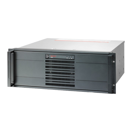
Product overview Product overview The C5240 is a powerful industrial PC with ATX motherboard for installation in a 19-inch rack. The device is suitable for various applications and requirements. The available processor options allow you to use the industrial PC for the following applications, among others: •... -
Page 10: Structure
Product overview Structure Fig. 1: Structure Table 1: Legend - C5240 structure Component Description Front flap Access to ATX and reset button, USB interfaces, drives, hard drive caddy, front fan filter mat Front flap lock Opening the front flap Status LEDs Status display for hard disk, fieldbus and power... -
Page 11: Interface Description
Product overview Interface description In the basic configuration, the C5240 includes the following interfaces: • Power supply (X101) • PS/2 mouse and keyboard (X103, X104) • USB (X108-X111, X212, X213) • Ethernet RJ45 (X112, X113) • DVI (X114, X115) • RS232 (X116) •... -
Page 12: Power Supply
The positive pole of the supply voltage at PIN 1 of the power supply socket (X101) is looped through to PIN 3 of the socket (X102). PIN 3 thus serves as the positive pole for PC-ON. Fig. 6: Socket External wiring Version: 3.0 C5240... -
Page 13: Fig. 7 Ps/2 Mouse And Keyboard
Mouse Data Reserved Ground (S)VCC 5 V supply voltage MCLK Mouse Clock Reserved Table 6: PS/2 interface keyboard pin assignment Name Description KDAT Keyboard data MDAT Mouse Data Ground (S)VCC 5 V supply voltage KCLK Keyboard Clock MCLK Mouse Clock C5240 Version: 3.0... -
Page 14: Usb
Fig. 8: USB interfaces rear side pin numbering Table 7: USB interface pin assignment Connection Typical assignment Vbus White Green Black StdA_SSRX - Blue StdA_SSRX + Yellow GND_DRAIN StdA_SSTX - Purple StdA_SSTX + Orange For USB 2.0, only pins 1 to 4 are relevant. Version: 3.0 C5240... -
Page 15: Ethernet Rj45
LED lights up green. The LED flashes when data transmission is in progress on the interface. The LED on the right in the figure indicates the speed of the data transmission. If the speed is 100 Mbit/s the LED is orange, at 1000 Mbit/s it is green. C5240 Version: 3.0... -
Page 16: Dvi
BIOS setup if required. X116 Fig. 11: RS232 interface pin numbering Table 10: COM1 interface pin numbering Name Description Data Carrier Detect Receive Data Transmit Data Data Terminal Ready Ground Data Set Ready Request to Send Clear to Send Ring Indicator Version: 3.0 C5240... -
Page 17: Displayport
LVDS lane 2 + Ground LVDS lane 2 - LVDS lane 3 + Ground LVDS lane 3 - Config 1 Config 2 AUX channel + Ground AUX channel - Hot-plug detection Power supply: ground Power supply: 3.3 V / 500 mA C5240 Version: 3.0... -
Page 18: Audio Connections
The three sockets are brought out for 3.5 mm jack plugs. The pins of the jack plugs are assigned as follows: Fig. 14: Jack plug pin assignment Table 12: Jack plug pin assignment Connection Left sound signal Right sound signal Common ground (return) Version: 3.0 C5240... -
Page 19: Status Leds
TwinCAT Config blue/red flashing TwinCAT Config (fieldbus error) green TwinCAT Run green/red flashing TwinCAT Run (fieldbus error) HDD (hard disk) Accessing storage media The activity of NVM Express™ SSDs is not displayed via the HDD LED. C5240 Version: 3.0... -
Page 20: Name Plate
HDD/SSD 0: HDD/SSD 1: HDD/SSD 2: xxxxxxxxxxxx xxxxxxxxxxxx Fig. 16: Name plate Table 14: Legend C5240 name plate Description Model: The last four digits indicate the device generation. Serial number (BTN) Date of manufacture Mainboard Main memory MAC addresses of the Ethernet interfaces (X112, X113) -
Page 21: Commissioning
4. Check the contents for visible shipping damage. 5. In case of discrepancies between the package contents and the order, or in case of transport damage, please inform Beckhoff Service (see Chapter 10.1 Service and Support [} 51]). C5240 Version: 3.0... -
Page 22: Rack Installation
Fig. 17: Device dimensions Beckhoff provides the following ordering option C9900-M712 with telescopic rails and brackets: • C9900-M712: Drawer slides for C5210 and C5240. Telescopic rails and bracket set for installation in 19-inch racks The telescopic rails and brackets allow you to pull the industrial PC out of the rack. This makes it easier to open or connect the industrial PC, for example. -
Page 23: Connecting The Industrial Pc
If you need a replacement for the power supply connector and strain relief housing, you can order this from Beckhoff Sales by specifying the following ordering option: • C9900-P917: Power supply connector for industrial PC, connector with strain relief for the external supply cable with 24 V label... -
Page 24: Grounding Of The Industrial Pc
Potential differences are minimized and electrical currents are diverted to the ground through grounding or potential equalization of electronic devices. This is to prevent dangerous touch voltages and electromagnetic interference. The protection provided by the devices may be impaired by non-intended use. Version: 3.0 C5240... -
Page 25: Fig. 21 Threaded Hole Functional Earthing
Use either a wide, flat ground strap or a round conductor with a minimum cross-section of 10 mm for the ground connection. In the case of a round conductor, also use a cable lug with a ring and place the ring over the grounding bolt. Fig. 21: Threaded hole Functional earthing C5240 Version: 3.0... -
Page 26: Connecting Cables And Power Supply
The connection of incorrect battery packs can lead to damage to the industrial PC with C9900-P209 power supply unit option and to the battery packs. • Only connect the C9900-U330 Beckhoff battery pack to your industrial PC. As an alternative to the 100-240 V AC power supply unit in the basic configuration, you can order the industrial PC with a 24 V DC power supply unit. -
Page 27: Table 15 Order Identifier Battery Pack
If you ordered your device with the C9900-P209 power supply unit with an integrated UPS, then you can connect an external battery pack and install it on a DIN rail near to the PC. Use only Beckhoff battery packs for this: Table 15: Order identifier battery pack... -
Page 28: Switching The Industrial Pc On And Off
Switching off the PC before the running software is terminated and the operating system is shut down can lead to data loss. • Quit the running software and shut down the operating system before switching off the PC. Version: 3.0 C5240... - Page 29 You can use the UPS output to supply another device, such as a control panel as an operating element. If the power supply fails without a UPS, both the industrial PC and devices supplied via the UPS output are switched off directly. C5240 Version: 3.0...
- Page 30 You then use the installation package to install the UPS software components. The UPS software components come with a detailed help function. Call up the help files either directly from the configuration register by clicking the Help button or start the file under Start > Programs > Beckhoff > UPS software components.
-
Page 31: Configuration
PC with a UPS. The Beckhoff Device Manager is a tool for detailed system diagnostics of hardware and software components. You will be shown the procedure for the first start of the Beckhoff Device Manager as well as for manual start. -
Page 32: Ups Configuration
Secure passwords Strong passwords are an important prerequisite for a secure system. Beckhoff supplies the device images with standard user names and standard passwords for the operating system. It is imperative that you change these. Controllers are shipped without a password in the UEFI/BIOS setup. Beckhoff recommends assigning a password here as well. -
Page 33: Fig. 25 Select Ups
Configuration Fig. 25: Select UPS 2. Select the manufacturer Beckhoff from the drop-down menu. Fig. 26: Select manufacturer 3. Select at Model/Interface Beckhoff P24Vxxxx. 4. Select the port COM4. 5. Click Finish. Fig. 27: Select model/interface & port 6. Click Apply. C5240 Version: 3.0... -
Page 34: Fig. 28 Apply Configuration
Configuration Fig. 28: Apply configuration ð You have configured the UPS. The status of the connected UPS is displayed. Fig. 29: UPS status Version: 3.0 C5240... -
Page 35: Decommissioning
5. Make a note of the wiring of all data transmission cables if you want to restore the cabling with another device. 6. Disconnect the data transmission cables from the industrial PC. 7. Finally, disconnect the ground connection. ð You have disconnected the power supply and the cables. C5240 Version: 3.0... -
Page 36: Disassembly And Disposal
• Electronic parts such as fans and circuit boards must be disposed of in accordance with national electronic scrap regulations. • Stick insulating tape over the poles of the CR2032 battery on the motherboard and dispose of the battery via the local battery recycling. Version: 3.0 C5240... -
Page 37: Maintenance
NOTICE Use of incorrect spare parts The use of spare parts not ordered from Beckhoff Service can lead to unsafe and faulty operation. • Only use spare parts that you have ordered from Beckhoff Service. Beckhoff industrial PCs are manufactured from components of the highest quality and robustness. They are selected and tested for best interoperability, long-term availability and reliable function under the specified environmental conditions. -
Page 38: Table 16 Replacement Recommendations For Pc Components
Motherboard battery 5 years Beckhoff is excluded from liability in the event of possible damage occurring during maintenance work. In order to avoid damage caused by electrostatic discharge when replacing device components, protective measures are recommended. Below are some suggestions. -
Page 39: Access To Device Components
To reinstall the card holder afterwards, follow the steps below, shown in Figure 32: 1. Release all plastic elements of the card holder (section A). 2. Insert the holder back into the industrial PC with the left side first (section B). C5240 Version: 3.0... -
Page 40: Fig. 32 Mounting Card Holder
1. Place the housing cover on the housing 1 cm before the target position (section A). 2. Slide the housing cover 1 cm forward (section B). 3. Fasten the cover with the two M4 screws (section C). ð You have mounted the housing cover again. Fig. 33: Mounting housing cover Version: 3.0 C5240... -
Page 41: Replacing The Battery
NOTICE Incorrect battery type Inserting the wrong type of battery can damage the device. • Only replace the battery with a replacement battery from Beckhoff Service. • When replacing the battery, make sure that the polarity is correct. NOTICE Battery damage Incorrect handling of the motherboard battery can damage it. -
Page 42: Replacing The Storage Media
If you want to exchange a storage medium according to Beckhoff's recommendation, you must copy the data from the old to the new storage medium. You can use the Beckhoff Service Tool (BST) for this purpose. BST is a graphical backup and restore program for PCs with a Windows operating system. You can create an image of your operating system and use it to back up the operating system. -
Page 43: Fig. 36 Exchange Hard Disk Hard Drive Caddy
3. Pull the key of the hard drive caddy to unlock it (section B). 4. Open the hard drive caddy (section C). 5. Pull the SSD out of the hard drive caddy by the protruding Beckhoff sticker (section D). 6. Reinsert the new SSD in the same orientation. -
Page 44: Exchange Filter Mat
You can equip your industrial PC with additional hard disks and SSDs, which are permanently installed in 5¼-inch drive slots via mounting adapters (see Fig. 35). You cannot replace these storage media on your own. To replace the hard disks and SSDs in mounting adapters, contact Beckhoff Service (Chapter 10.1 Service and support [} 51]). -
Page 45: Fig. 39 Exchange Filter Mat
If you want to replace the filter mat, you can choose one of the two ordering options for a replacement mat, depending on the equipment of your PC: • C9900-Z326: Filter mat for fans in C5240 with three 5¼-inch slots, 5 pcs • C9900-Z327: Filter mat for fans in C5240 with six 5¼-inch slots, 5 pcs The procedure for replacing the filter mat is the same in both cases. -
Page 46: Replacing The Fan
The industrial PC may be damaged if the wrong type of fan is installed. • Only replace the fans with a fan from Beckhoff Service. Before you can replace the fan and CPU cooler, you must gain access to the interior of the industrial PC (see chapter 7.2.1 Access to device components [} 39]). -
Page 47: Fig. 40 Exchange Front Fan
8. Connect the supply cable to the motherboard. 9. Fasten the four M4 screws again. 10. Reinsert the filter mat. Alternatively, you can order a new filter mat from Beckhoff Sales and insert it. 11. Replace the filter cover. 12. Fasten the filter cover with the two M4 screws. -
Page 48: Fig. 41 Exchange Cpu Cooler
7. Turn the locking elements in the opposite direction of the arrows shown on them to lock the cooler onto the motherboard. ð You have replaced the CPU cooler. Fig. 41: Exchange CPU cooler The old fan must be disposed of in accordance with the national electronic waste regulations. Version: 3.0 C5240... -
Page 49: Troubleshooting
Nothing happens after the Missing power supply of the Check the power supply cable industrial PC has been switched on industrial PC Call Beckhoff Service Other cause The industrial PC does not boot Setup settings are incorrect Check the setup settings... -
Page 50: Technical Data
Technical data Technical data Table 20: Technical data Product designation C5240 Dimensions (W x H x D) 482 x 509 x 81 mm Weight of the basic configuration Approx. 17 kg Supply voltage 100–240 V , max. 3 A, 50 – 60 Hz Power consumption: approx. -
Page 51: 10 Appendix
33415 Verl Germany Phone: + 49 5246/963-0 email: info@beckhoff.de The addresses of the worldwide Beckhoff branches and agencies can be found on our website at http:// www.beckhoff.com/. You will also find further documentation for Beckhoff components there. C5240 Version: 3.0... -
Page 52: 10.2 Approvals
FCC approvals for Canada FCC: Canadian Notice This device does not exceed the class A limits for radiation, as specified by the Radio Interference Regulations of the Canadian Department of Communications. Version: 3.0 C5240... - Page 53 Disassembly of the strain relief housing..................Fig. 21 Threaded hole Functional earthing ....................Fig. 22 Wiring diagram ..........................Fig. 23 Beckhoff Device Manager - Change passwords ................Fig. 24 Beckhoff Device Manager – Start page ..................Fig. 25 Select UPS........................... Fig. 26 Select manufacturer ........................
- Page 54 List of tables List of tables Table 1 Legend - C5240 structure ......................Table 2 Current carrying capacity power supply unit ................Table 3 Power supply socket (X101) pin assignment ................Table 4 Socket external wiring (X102) pin assignment ................
- Page 56 More Information: www.beckhoff.com/c5240 Beckhoff Automation GmbH & Co. KG Hülshorstweg 20 33415 Verl Germany Phone: +49 5246 9630 info@beckhoff.com www.beckhoff.com...
Need help?
Do you have a question about the C5240 and is the answer not in the manual?
Questions and answers