
Related Manuals for Beckhoff C5240


Summary of Contents for Beckhoff C5240
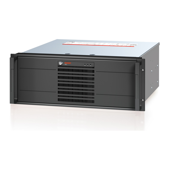
- Page 1 Installation and Operating instructions for C5240 | 19-inch slide-in Industrial PC Version: 1.0 Date: 2019-02-08...
-
Page 3: Table Of Contents
Operator requirements 2 Product Description Product overview Appropriate Use Opening the Housing Access to the battery Changing the filter mat Interfaces from C5240 2.6.1 PS/2 connections (X103, X104) 2.6.2 Serial interface COM1 (X105) 2.6.3 Network connection LAN1, LAN2 (X106, X107) 2.6.4... - Page 4 4.2.2 Maintenance 4.2.3 Replacing the Battery on the Motherboard Emergency procedures Shutting down 4.4.1 Disposal 5 Troubleshooting 6 Assembly dimensions 7 Technical Data 8 Appendix Beckhoff Support and Service 8.1.1 Beckhoff branches and partner companies 8.1.2 Beckhoff company headquarters C5240...
- Page 5 Table of contents Approvals for USA and Canada FCC Approvals for the United States of America FCC Approval for Canada C5240...
-
Page 6: Foreword
Modifications to hardware or software configurations other than those described in the documentation are not permitted, and nullify the liability of Beckhoff Automation GmbH & Co.KG. 1.1.6 Delivery conditions In addition, the general delivery conditions of the company Beckhoff Automation GmbH & Co.KG apply. C5240... -
Page 7: Description Of Safety Symbols
CAUTION Hazard to devices and environment If you do not adhere the notice adjoining this symbol, there is obvious hazard to materials and environment. Attention Note or pointer This symbol indicates information that contributes to better understanding. Note C5240... -
Page 8: Basic Safety Measures
• if connecting cables internal to the PC are removed or inserted during operation. • if plug-in cards are removed or inserted when the PC is switched on. C5240... -
Page 9: Operator's Obligation To Exercise Diligence
1.4.3 Operator requirements Anyone who uses the Industrial PC must have read these operating instructions and must be familiar with all the functions of the software installed on the Industrial PC to which he has access. C5240... -
Page 10: Product Description
C5240 | 19-inch slide-in Industrial PC The C5240 Industrial PC expands the C52xx Industrial PC series by a version with four height units and seven PCI and PCIe plug-in card slots in 24 V DC or 110…230 V AC versions. The basic configuration includes three 5¼-inch drive bays behind the front flap. -
Page 11: Appropriate Use
Product Description 2.2 Appropriate Use The C5240 Industrial PC has been designed as a rack mount PC for fitting into 19-inch racks used in machine and plant engineering applications. Risk of explosion! The Industrial PC must not be used where there is a risk of explosion. - Page 12 The standard ATX Motherboard (1) with six slots for plug-in cards (2) is located under the housing cover. The power supply unit (3) and the hard drive (4) are easily accessible. The connections to the outside are located at the rear of the housing (5) and behind the front flap. C5240...
-
Page 13: Access To The Battery
Replace battery only with the identical type or an alternative type recommended by the WARNING manufacturer. Notice correct polarity! Polarität der Batterie: Handling of Lithium Batteries Lithium Batteries should not be recharged, exposed to fire, opened and they should be WARNING protected against sunlight and moisture. C5240... -
Page 14: Changing The Filter Mat
Beckhoff filter mat. Order number Description C9900-Z326 Filter mat for C5240 with three 5¼-inch slots, 5 per pack C9900-Z327 Filter mat for C5240 with six 5¼-inch slots, 5 per pack Front view with filter cover Access to the filter mat is obtained behind the front flap. This must be opened with its key. After removing the two cross-head screws (2) the filter cover (1) can be removed. -
Page 15: Interfaces From C5240
Product Description 2.6 Interfaces from C5240 X116 X105 X104 X117 X115 X106 X107 X103 X118 X109 X111 X114 X119 X108 X110 2.6.1 PS/2 connections (X103, X104) The upper PS/2 connector (X104) allows a PS/2 mouse to be used, while a PC keyboard can be connected to the lower PS/2 connector (X103). -
Page 16: Usb Interfaces And Control Elements
The LED FB is a multi-color LED and shows the status of fieldbus and TwinCAT: Color LED FB Description TwinCAT STOP blue TwinCAT CONFIG blue/ red blinking TwinCAT CONFIG with Bus Error green TwinCAT RUN green/ red blinking TwinCAT RUN with Bus Error C5240... -
Page 17: Installation
4. Please keep the associated paperwork. It contains important information for handling the unit. 5. Check the contents for visible shipping damage. 6. If you notice any shipping damage or inconsistencies between the contents and your order, you should notify Beckhoff Service. C5240... -
Page 18: Installation Of The Pc In The Control Cabinet
Installation 3.2 Installation of the PC in the control cabinet The C5240 Industrial PC has been designed as a rack mount PC for fitting into 19-inch racks used in machine and plant engineering applications. The ambient conditions specified for operation must be observed (see chapter Technical Data). -
Page 19: Power Supply Of The Industrial Pc
Listed, Detachable, maximum 4.5 m (14.76 ft.) long; rated minimum 250 V, 10 A, Type SJT or Type SVT; one end terminates in NEMA 6-15P/-20P grounding-type attachment plug, other end in appliance coupler. Minimum temperature rating of supply cables should be 80 °C. C5240... -
Page 20: Power Supply With
The new Beckhoff power supply technology approach addresses this problem and now offers the user the option of switching the PC off without the need for using the battery, thereby reducing the load on the battery. -
Page 21: Current Carrying Capacity Of The 24 V Power Supply Unit
Two 5-pin plug connectors with CAGE CLAMP connection are installed at the PC housing in order to connect the 24 V power supply and the external components. Pin assignment power supply Pin assignment for connecting the power supply and X101 the battery pack (optional) Function 24 V Power Supply Battery Pack (with UPS only) C5240... -
Page 22: Fitting The Cables
4. Relieve the strain on the supply cable by fixing it in place with the cable clamp and fixing screws. 5. Fix the upper part of the strain relief housing by snapping it onto the lower part. C5240... -
Page 23: Connecting Power Supply
1.4 A (max. 2.5 A from 2016 and later). • Once the PC has been de-energized via the UPS software, the UPS output is switched to 0 V. Any connected panel is thus switched off, and total discharge of the rechargeable battery is prevented. C5240... -
Page 24: Wiring Diagram
Wiring according to the wiring diagram (the circuit of PC_ON and Power-Status is symbolical): Wiring diagram external switch and power supply Connection of the Battery Pack and UPS Output Connection of the Battery Pack and UPS Output only in combination with integrated UPS (order option). Note C5240... -
Page 25: Connecting The Industrial Pc
2. Insert the power supply cable that you have assembled into the Industrial PC's power supply socket. Then connect it to your external 24 V power supply. Use same type of rechargeable battery If a 24 V UPS is installed, the same type of rechargeable battery must be used. Attention C5240... -
Page 26: Operating Instructions
If the PC was ordered without operating system, you have to install the operating system and the driver software for any auxiliary hardware yourself. Please follow the instructions in the documentation for the operating system and the additional devices. C5240... -
Page 27: Servicing And Maintenance
Housing components (polycarbonate, polyamide (PA6.6)) are suitable for plastic recycling • Metal parts can be sent for metal recycling • Electronic parts such as disk drives and circuit boards must be disposed of in accordance with national electronics scrap regulations. C5240... -
Page 28: Troubleshooting
Nothing happens after the Industrial No power supply to the Industrial Check power supply cable PC has been switched on Other cause Call Beckhoff Service The Industrial PC does not boot CD in drive Remove CD and press any fully... -
Page 29: Assembly Dimensions
Assembly dimensions 6 Assembly dimensions Industrial PC C5240 Notice mounting orientation The assembly of the unit must take place with the orientation diagrammed here. Attention All dimensions in mm. Front view Side view Top view C5240... - Page 30 Assembly dimensions Notice mounting orientation The assembly of the unit must take place with the orientation diagrammed here. Attention All dimensions in mm. With guide rail Maedler Accuride 2907 Side view Top view C5240...
-
Page 31: Technical Data
7 Technical Data Risk of explosion! Do not use the Industrial PC in areas of explosive hazard! Danger Product description C5240 Dimensions (B x H x T) 482 x 177 x 511 mm (with handles) Weight 17.0 kg (basic configuration) -
Page 32: Appendix
Please contact your Beckhoff branch office or partner company for local support and service on Beckhoff products! The contact addresses for your country can be found in the list of Beckhoff branches and partner companies: www.beckhoff.com. You will also find further documentation for Beckhoff components there. -
Page 33: Approvals For Usa And Canada
Technological changes to the device may cause the loss of the FCC approval. Note 8.4 FCC Approval for Canada FCC: Canadian Notice This equipment does not exceed the Class A limits for radiated emissions as described in the Radio Interference Regulations of the Canadian Department of Communications. C5240...
Need help?
Do you have a question about the C5240 and is the answer not in the manual?
Questions and answers