Beckhoff CP72 Series Manual
Hide thumbs
Also See for CP72 Series:
- Installation and operating instructions manual (31 pages) ,
- Installation and operating instructions manual (38 pages)
Table of Contents
Advertisement
Quick Links
Advertisement
Chapters
Table of Contents

Related Manuals for Beckhoff CP72 Series


Summary of Contents for Beckhoff CP72 Series
- Page 1 Manual | EN CP72xx Panel PC 2024-02-02 | Version: 3.0...
-
Page 3: Table Of Contents
Grounding the panel PC.................... 24 4.3.2 Connecting cables and power supply ................ 26 Switching the panel PC on and off .................... 28 5 Beckhoff Device Manager ........................ 30 6 Decommissioning ........................... 32 Disconnecting the power supply and cables ................... 32 Disassembly and disposal....................... 33 7 Maintenance ............................ 34... - Page 4 Table of contents Version: 3.0 CP72xx...
-
Page 5: Notes On The Documentation
Copyright © Beckhoff Automation GmbH & Co. KG. Publication of this document on websites other than ours is prohibited. Offenders will be held liable for the payment of damages. All rights reserved in the event of the grant of a patent, utility model or design. -
Page 6: For Your Safety
Exclusion of liability Beckhoff shall not be liable in the event of non-compliance with this documentation and thus the use of the devices outside the documented operating conditions. -
Page 7: Fundamental Safety Instructions
For your safety Fundamental safety instructions The following safety instructions must be observed when handling the device. Application conditions • Do not use the device under extreme environmental conditions. • Only use the device in hazardous areas if it is explicitly designed for this purpose. •... -
Page 8: Notes On Information Security
For your safety Notes on information security The products of Beckhoff Automation GmbH & Co. KG (Beckhoff), insofar as they can be accessed online, are equipped with security functions that support the secure operation of plants, systems, machines and networks. Despite the security functions, the creation, implementation and constant updating of a holistic security concept for the operation are necessary to protect the respective plant, system, machine and networks against cyber threats. -
Page 9: Product Overview
Product overview Product overview The CP72xx Economy Panel PC is designed for installation on the mounting arm and represents a powerful platform for use in machine and system engineering. Thanks to its processors, you can use the panel PC for the following applications, among others: •... -
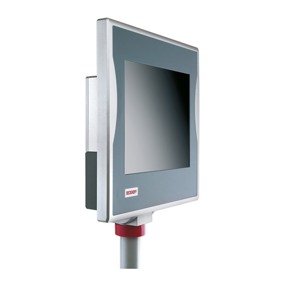
Page 10: Structure
Product overview Structure The figure only shows an example device. Fig. 1: Structure Table 1: CP72xx structure Component Description Side cover Access to battery and storage medium Name plate Information on the equipment of the panel PC Connection compartment Access to interfaces Mounting arm adapter Adapter for installation on the mounting arm tube Mounting arm tube... -
Page 11: Interface Description
Product overview Interface description In the basic configuration, the panel PC includes the following interfaces: • Power supply (X101) • Ethernet RJ45 (X106) The interfaces are located on the rear side of the panel PC behind two plastic caps. Loosen and remove the four M4 screws and then remove the plastic caps (see Fig. -
Page 12: Power Supply
The main supply voltage is applied between pins 5 (0 V) and 6 (24 V). If the panel PC is equipped with an integrated uninterruptible power supply (UPS), an external battery can additionally be connected to PIN 1 and PIN 2. The Beckhoff option C9900-U330 is available for this purpose. Table 2: Wiring with 8-core cable... -
Page 13: Ethernet Rj45
Product overview 3.2.2 Ethernet RJ45 The basic version of the panel PC has an Ethernet RJ45 interface (X106) in the form of a push-pull built-in socket. The 100Base-T, 1000Base-T and 2500Base-T Ethernet standards enable the connection of corresponding network components and data rates of 100/1000/2500 Mbit/s. The required speed is selected automatically. -
Page 14: Optional Interfaces
Product overview Optional interfaces Various interface options are available to expand your panel PC with additional interfaces beyond the basic configuration. The following table provides information about the available interfaces depending on the device generation: Table 6: CP72xx interface options Ordering option Description Device generation C9900-E185... -
Page 15: Name Plate
Product overview Name plate The name plate provides information about the panel PC equipment. The name plate shown here serves only as an example. xxxxxxxx xxxxxxxxxxxx xxxxxxxxxxxx Fig. 4: Name plate Table 7: Legend CP72xx name plate Description Model: The last four digits indicate the device generation. Address of the vendor Symbols Note: Here are the symbols applicable to the device such as CE, EAC, UKCA,... -
Page 16: Key Functions
Product overview Key functions Table 8: Key functions CP72xx Function Move the cursor one step in the corresponding direction Home = cursor to beginning of the line Home End = cursor to end of the line Pg Up = scroll forward one page Pg Up Pg Dn Pg Dn = turn back one page... -
Page 17: Connection Cable
Product overview Function keys = functions of the keys determined by the software Special keys = special keys with LED that can be controlled by the TwinCAT automation software Einschub Einschub Einschub Einschub Streifen Streifen Streifen Streifen Connection cable Optionally, ready-made connecting cables for all connections are available in various lengths. You can order them using the following article descriptions: Table 9: Power supply cable Connecting cable... -
Page 18: Table 10 Network Cable
Product overview Table 10: Network cable Connecting cable Network cable with IP65 plug C9900-K363 Network cable for CP32xx, CP37xx and CP72xx, length 2 m, pre-assembled, push- pull Ethernet connector IP65, second end RJ45, IP20 C9900-K281 Network cable for CP32xx, CP37xx and CP72xx, length 3 m, pre-assembled, push- pull Ethernet connector IP65, second end RJ45, IP20 C9900-K282 Network cable for CP32xx, CP37xx and CP72xx, length 5 m, pre-assembled, push-... -
Page 19: Accessories
Product overview Accessories You can order your panel PC with accessories already mounted ex factory. The following Beckhoff options are available: • C9900-M400: Toolboard for keyboard or tools, mounted on the bottom of a Control Panel or Panel PC CP7xxx, can only be ordered together with the control panel or panel PC. -
Page 20: Commissioning
You can either order a Beckhoff protective film individually and fit it yourself retrospectively, or you can order the film for fitting directly ex factory. Please refer to the price list for the available protective films according to the display size of your device. -
Page 21: Transport And Unpacking
4. Check your delivery for completeness by comparing it with your order. 5. Check the contents for visible shipping damage. In case of discrepancies between the package contents and the order, or in case of transport damage, please inform Beckhoff Service (see Chapter 10.1 Service and Support [} 43]). CP72xx Version: 3.0... -
Page 22: Installation
• Do not expose the panel PC to direct sunlight. Regardless of which of the Beckhoff mounting arm adapters you have chosen, the procedure for installing the mounting arm tube is the same. Depending on whether you have oriented the mounting arm adapter upwards or downwards, the mounting arm tube has to be installed on the adapter in the same direction. -
Page 23: Fig. 7 Installing The Mounting Arm Tube
Commissioning Figure 7 shows an example of the procedure with the standard mounting arm adapter facing upwards. To install the mounting arm tube on the mounting arm adapter, proceed as follows: 1. Slide the red plastic cover ring upwards (section A). 2. -
Page 24: Connecting The Panel Pc
Commissioning Connecting the panel PC CAUTION Risk of electric shock Dangerous touch voltages can lead to electric shock. To avoid electric shock, observe the following: • Never connect or disconnect the device cables during a thunderstorm. • Provide protective earthing for handling the device. To prepare the industrial PC for operation, it must be connected. -
Page 25: Fig. 8 Grounding Bolt For Functional Earthing
Commissioning The functional earth is necessary for the EMC of the device. The functional earth is established via the connection of the grounding bolt in the connection section of the panel PC (see Fig. 8). Use wires with a cross-section of at least 4 mm or a flat conductor for the ground connection, as the circumference of the conductor should be as large as possible. -
Page 26: Connecting Cables And Power Supply
If you ordered your device with an integrated UPS, then you can connect an external battery pack and install it on a DIN rail near to the PC. Use only Beckhoff battery packs for this: • C9900-U330: universal battery pack for PCs and panel PCs in any configuration PIN 4 and 5 of the battery pack are available for looping through a 24 V power supply. -
Page 27: Fig. 9 Wiring Diagram
Commissioning Industrial PC power connector Battery Power 24 V 24 V DC L max = 10 m ext. switch 1,5 mm / AWG14 Power status UPS Output 24 V DC 24 V/3,4 Ah 30 V/9 A C9900-U330 battery pack Fig. 9: Wiring diagram For more information on the battery pack, please refer to the corresponding manual. -
Page 28: Switching The Panel Pc On And Off
When you switch on the PC for the first time, the optionally pre-installed operating system will be started. For any additional hardware you have connected, you have to install the drivers yourself afterwards. In addition, the Beckhoff Device Manager starts automatically. The Device Manager is a software from Beckhoff that supports you in configuring the PC. - Page 29 You then use the installation package to install the UPS software components. The UPS software components come with a detailed help function. Call up the help files either directly from the configuration register by clicking the Help button or start the file under Start > Programs > Beckhoff > UPS software components.
-
Page 30: Beckhoff Device Manager
• User name: Administrator • Password: 1 You also have the option of using the Beckhoff Device Manager to remotely configure the industrial PC via a web browser. More detailed information is available in the Beckhoff Device Manager manual. First start Beckhoff Device Manager When your industrial PC is booted for the first time, the Beckhoff Device Manager also starts automatically for the first time. -
Page 31: Fig. 11 Beckhoff Device Manager - Start Page
Secure passwords Strong passwords are an important prerequisite for a secure system. Beckhoff supplies the device images with standard user names and standard passwords for the operating system. It is imperative that you change these. Controllers are shipped without a password in the UEFI/BIOS setup. Beckhoff recommends assigning a password here as well. -
Page 32: Decommissioning
Decommissioning Decommissioning NOTICE Hardware damage due to power supply A connected power supply can cause damage to the panel PC during disassembly. • Disconnect the power supply from the device before starting to disassemble it. As part of the decommissioning of the panel PC, you must first disconnect the power supply and cables. Afterwards, you can dismount the device from the mounting arm. -
Page 33: Disassembly And Disposal
Decommissioning Disassembly and disposal In order to be able to dismount the panel PC from the mounting arm, you must first have disconnected the power supply and the cables (see Chapter 6.1 Disconnecting the power supply and cables [} 32]). Disassembly mounting arm tube NOTICE Damage to property due to falling down If the panel PC is suspended from the ceiling and you remove the mounting arm tube from the mounting... -
Page 34: Maintenance
You can clean the front screen of the panel PC during operation. In order to avoid inadvertent touch entries when doing this, you must first set the device to "Cleaning Mode" with the help of the Beckhoff Control Tool. Also make sure that you not only clean the display area, but also the edge of the glass pane. Impurities in... -
Page 35: Fig. 13 Select "Cleaning Mode
Maintenance The Beckhoff Control Tool does not start automatically when the panel PC starts up. Proceed as follows to activate the "Cleaning Mode" of the Beckhoff Control Tool: 1. Go to the Beckhoff Control Tool to start it. ð When the tool is started, a small sun symbol appears in the taskbar. -
Page 36: Table 13 Replacement Recommendations For Pc Components
Motherboard battery 5 years Beckhoff is excluded from liability in the event of possible damage occurring during maintenance work. In order to avoid damage caused by electrostatic discharge when replacing device components, protective measures are recommended. Below are some suggestions. -
Page 37: Fig. 15 Access To Battery And Storage Media
Maintenance • Do not walk around with electronic components in your hand if they are not in ESD packaging. Access to battery and storage media To be able to replace the battery and the storage media, you must first gain access to these device components. -
Page 38: Replacing The Battery
Replace the battery with R/C (BBCV2), order number CR2032, nominal voltage 3 V. Using any other battery may cause fire or explosion. • Only replace the battery with a replacement battery from Beckhoff Service. • When replacing the battery, make sure that the polarity is correct. -
Page 39: Replacing The Storage Media
If you want to exchange a storage medium according to Beckhoff's recommendation, you must copy the data from the old to the new storage medium. You can use the Beckhoff Service Tool (BST) for this purpose. BST is a graphical backup and restore program for PCs with a Windows operating system. You can create an image of your operating system and use it to back up the operating system. -
Page 40: Fig. 18 Replacing The Cfast
Maintenance 3. Insert the new CFast into the PC in the same orientation until it protrudes just a bit from the PC. 4. Press the CFast into the PC. ð You have replaced the CFast. Fig. 18: Replacing the CFast Version: 3.0 CP72xx... -
Page 41: Troubleshooting
No function of the panel PC No power supply to the panel PC Check the power supply cable Other cause Call Beckhoff Service The panel PC does not boot fully BIOS setup settings are incorrect Check BIOS setup settings (load... -
Page 42: Technical Data
CP72xx Supply voltage 22-30 V (24 V power supply unit) Power consumption Data sheet for calculating power consumption and power loss in the download finder - Data sheets: http://www.beckhoff.com/downloadfinder Protection rating IP65 Vibration resistance (sinusoidal EN 60068-2-6: 10 ... 58 Hz: 0.035 mm vibration) 58 ... -
Page 43: 10 Appendix
33415 Verl Germany Phone: + 49 5246/963-0 email: info@beckhoff.de The addresses of the worldwide Beckhoff branches and agencies can be found on our website at http:// www.beckhoff.com/. You will also find further documentation for Beckhoff components there. CP72xx Version: 3.0... -
Page 44: Approvals
Appendix 10.2 Approvals Your device has at least the following approvals: • CE • EAC • UKCA • FCC You will find all other applicable approvals on the name plate of your device. FCC approvals for the United States of America FCC: Federal Communications Commission Radio Frequency Interference Statement This device was tested and complies with the limits for a digital device of class A, according part 15 of the FCC regulations. - Page 45 Installing the mounting arm tube ....................Fig. 8 Grounding bolt for functional earthing ..................Fig. 9 Wiring diagram ..........................Fig. 10 Beckhoff Device Manager - Change passwords ................Fig. 11 Beckhoff Device Manager – Start page ..................Fig. 12 Disassembly mounting arm tube....................Fig. 13 Select "Cleaning Mode"...
- Page 46 List of tables List of tables Table 1 CP72xx structure.......................... Table 2 Wiring with 8-core cable....................... Table 3 Wiring with 12-core cable......................Table 4 Controller classification based on device generation ..............Table 5 Ethernet interface pin assignment....................Table 6 CP72xx interface options ......................Table 7 Legend CP72xx name plate......................
- Page 48 More Information: www.beckhoff.com/cp72xx Beckhoff Automation GmbH & Co. KG Hülshorstweg 20 33415 Verl Germany Phone: +49 5246 9630 info@beckhoff.com www.beckhoff.com...
Need help?
Do you have a question about the CP72 Series and is the answer not in the manual?
Questions and answers