Beckhoff CP6606-0001-0020 Installation And Operating Instructions Manual
‘economy' built-in panel pc
Hide thumbs
Also See for CP6606-0001-0020:

Related Manuals for Beckhoff CP6606-0001-0020


Summary of Contents for Beckhoff CP6606-0001-0020
- Page 1 Installation and Operating instructions for CP6606-0001-0020 „Economy“ Built-in Panel PC Version: 1.1 Date: 2016-10-07...
-
Page 3: Table Of Contents
3 Installation Transport and Unpacking 3.1.1 Transport 3.1.2 Unpacking Installation in the control cabinet 3.2.1 Preparation of the control cabinet 3.2.2 Installation in a control cabinet wall 3.2.3 Mounting of the Panel PC Wall installation with wall mounting frame (optional) CP6606-0001-0020... - Page 4 5 Troubleshooting 6 Assembly dimensions 7 Technical Data 8 Appendix Beckhoff Support and Service 8.1.1 Beckhoff branches and partner companies 8.1.2 Beckhoff company headquarters Approvals for USA and Canada FCC Approvals for the United States of America FCC Approval for Canada...
-
Page 5: Foreword
Modifications to hardware or software configurations other than those described in the documentation are not permitted, and nullify the liability of Beckhoff Automation GmbH & Co. KG. 1.1.6 Delivery conditions In addition, the general delivery conditions of the company Beckhoff Automation GmbH & Co. KG apply. CP6606-0001-0020... -
Page 6: Description Of Safety Symbols
CAUTION Hazard to devices and environment If you do not adhere the notice adjoining this symbol, there is obvious hazard to materials and environment. Attention Note or pointer This symbol indicates information that contributes to better understanding. Note CP6606-0001-0020... -
Page 7: Basic Safety Measures
Fitting work on the Panel PC can result in damage: • if metal objects such as screws or tools fall onto operating circuit boards • if connecting cables internal to the Panel PC are removed or inserted during operation. CP6606-0001-0020... -
Page 8: Operator's Obligation To Exercise Diligence
1.4.3 Operator requirements Anyone who uses the Panel PC must have read these operating instructions and must be familiar with all the functions of the software installed on the Industrial PC to which he has access. CP6606-0001-0020... -
Page 9: Product Description
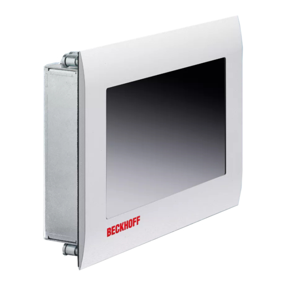
2.1 Product overview The compact built-in Panel PC The built-in Panel PC CP6606-0001-0020 with Ethernet port can be used as an independent Panel PC, remote desktop display or server terminal. The powerful 1 GHz ARM Cortex™ A8 CPU is suitable for versatile use in PLC and Motion Control applications in small and medium-sized machines, plants or buildings. -
Page 10: Appropriate Use
Product Description 2.2 Appropriate Use The built-in Panel PC CP6606-0001-0020 is suitable for versatile use in PLC and Motion Control applications in small and medium-sized machines, plants or buildings. A TFT display with touchscreen is accommodated in a steel housing with aluminium front. The Panel PC is installed in the front of control cabinets, for wall installation the wall mounting frame with order option C9900-M317 is necessary. -
Page 11: Interfaces
2.4.5 Serial interface COM1 (X107) The Panel PC has one serial interface COM1 (X107) using the type RS232, which is brought to a 9 pin SUB-D plug connector. 2.4.6 Ground connection (Ground) The Panel PC is grounded via the M4-screw connection (Ground). CP6606-0001-0020... -
Page 12: Access To The Battery And The Plug-In Card Slot
2.6 Status-LEDs The Status-LEDs are located near the power supply connector (X101): LED TC (1) X101 LED PWR (2) Description of the Status-LEDs TC (TwinCAT): Stop Mode green Run Mode blue Configuration Mode PWR (Power): green Busy green blinking Standby CP6606-0001-0020... -
Page 13: Installation
4. Please keep the associated paperwork. It contains important information for handling the unit. 5. Check the contents for visible shipping damage. If you notice any shipping damage or inconsistencies between the contents and your order, you should notify Beckhoff Service. CP6606-0001-0020... -
Page 14: Installation In The Control Cabinet
Installation 3.2 Installation in the control cabinet The Panel PC CP6606-0001-0020 is designed for mounting in control cabinets in machine and plant engineering applications. The ambient conditions specified for operation must be observed (see chapter Technical Data). 3.2.1 Preparation of the control cabinet The control cabinet wall must be prepared with the required mounting opening according to the Panel PC’s dimensions (see chapter... -
Page 15: Mounting Of The Panel Pc
Data, the wall thickness is between 1 mm and 5 mm. 1. Insert the Panel PC into the cutout. 2. Release the clamping levers with a 2.5 mm Allen key. 3. Turn the clamping levers to the side. 4. Retighten the screws. CP6606-0001-0020... -
Page 16: Wall Installation With Wall Mounting Frame (Optional)
3.3 Wall installation with wall mounting frame (optional) For wall installation the wall mounting frame with order option C9900-M317 is necessary. Reduced operating temperature Installation of the CP6606-0001-0020 in the wall mounting frame will reduce the Note maximum operating temperature down to 45 °C. -
Page 17: Cut Out Dimension
The ball catch counter parts are delivered with the wall mounting frame and have to be screwed onto the back side of the CP6606-0001-0020. The needed countersunk head screws M3x6 are delivered with the wall mounting frame as well. The holding force of the ball catch can be adjusted. -
Page 18: Fitting The Power Supply Cable
Put the plug connector into that lower part of the stain relief housing. Tighten the lacing cord and pinch off the plastic strap. Fixing the upper part of the stain relief housing Fix the upper part of the stain relief housing by snapping it onto the lower part. CP6606-0001-0020... -
Page 19: Connecting The Panel Pc
Earthing connections dissipate interference from external power supply cables, signal cables or cables to peripheral equipment. Establish a low-impedance connection from the earthing point on the Panel PC housing (see chapter Ground connection (Ground)) to the central earthing point on the control cabinet wall, in which the computer is being installed. CP6606-0001-0020... -
Page 20: Operating Instructions
The touch screen may only be actuated by finger tips or with the touch screen pen. The operator may wear gloves but there must be no hard particles such as metal shavings, Warning glass splinters embedded in the glove. CP6606-0001-0020... -
Page 21: Servicing And Maintenance
Housing components (polycarbonate, polyamide (PA6.6)) are suitable for plastic recycling. • Metal parts can be sent for metal recycling. • Electronic parts such as disk drives and circuit boards must be disposed of in accordance with national electronics scrap regulations. CP6606-0001-0020... -
Page 22: Troubleshooting
No power supply to the Panel PC Check power supply cable Cable not connected Correctly connect cable Call Beckhoff Service Panel PC boots, software starts, but Cause of the fault is either in the Call the manufacturer of the control does not operate correctly... -
Page 23: Assembly Dimensions
Assembly dimensions 6 Assembly dimensions Notice mounting orientation The assembly of the unit must take place with the orientation diagrammed here. Warning All dimensions are in mm. Front view Rear view with cutout-dimensions Side view CP6606-0001-0020... -
Page 24: Technical Data
Pixel errors in the TFT display are production-caused and represent no complaint- reason! Note Anomalies of the Touchscreen Anomalies of the touchscreen sensor are production-caused and represent no complaint-reason! Note Product name CP6606-0001-0020 Dimensions (B x H x T) See chapter Assembly dimensions Weight approx. 0.9 kg Supply voltage 24 V (20.4 –... -
Page 25: Appendix
Please contact your Beckhoff branch office or partner company for local support and service on Beckhoff products! The contact addresses for your country can be found in the list of Beckhoff branches and partner companies: www.beckhoff.com. You will also find further documentation for Beckhoff components there. -
Page 26: Approvals For Usa And Canada
Technological changes to the device may cause the loss of the FCC approval. Note 8.4 FCC Approval for Canada FCC: Canadian Notice This equipment does not exceed the Class A limits for radiated emissions as described in the Radio Interference Regulations of the Canadian Department of Communications. CP6606-0001-0020...
Need help?
Do you have a question about the CP6606-0001-0020 and is the answer not in the manual?
Questions and answers