Table of Contents
Advertisement
Quick Links
Advertisement
Chapters
Table of Contents

Related Manuals for Beckhoff CP6600


Summary of Contents for Beckhoff CP6600
- Page 1 Manual | EN CP6600 Panel PC 2/17/2022 | Version: 2.0...
-
Page 3: Table Of Contents
Disconnecting the power supply and cables ................... 25 Disassembly and disposal ....................... 26 6 Maintenance ............................. 27 Cleaning ............................ 27 Maintenance ............................ 27 6.2.1 Replacing the battery....................... 29 6.2.2 Replacing the storage medium .................. 30 7 Troubleshooting ............................ 31 8 Technical data............................ 32 9 Appendix .............................. 33 Service and support......................... 33 Approvals............................ 34 CP6600 Version: 2.0... - Page 4 Table of contents Version: 2.0 CP6600...
-
Page 5: Notes On The Documentation
Copyright © Beckhoff Automation GmbH & Co. KG. Publication of this document on websites other than ours is prohibited. Offenders will be held liable for the payment of damages. All rights reserved in the event of the grant of a patent, utility model or design. -
Page 6: For Your Safety
Exclusion of liability Beckhoff shall not be liable in the event of non-compliance with this documentation and thus the use of the devices outside the documented operating conditions. Description of safety symbols The following safety symbols are used in these operating instructions. -
Page 7: Fundamental Safety Instructions
• the operating instructions are in good condition and complete, and always available for reference at the location where the products are used. CP6600 Version: 2.0... -
Page 8: Notes On Information Security
For your safety Notes on information security The products of Beckhoff Automation GmbH & Co. KG (Beckhoff), insofar as they can be accessed online, are equipped with security functions that support the secure operation of plants, systems, machines and networks. Despite the security functions, the creation, implementation and constant updating of a holistic security concept for the operation are necessary to protect the respective plant, system, machine and networks against cyber threats. -
Page 9: Product Overview
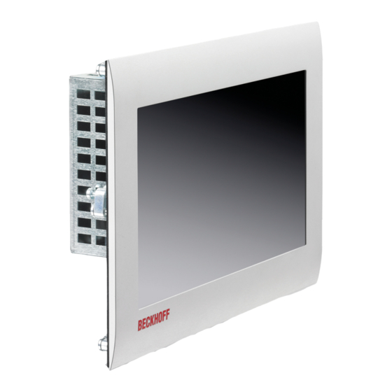
Product overview Product overview The built-in Panel PC CP6600 is designed for installation in the front of a control cabinet or control housing and can be used in a variety of ways in machine and system engineering. The Panel PC is suitable for universal use in PLC as well as Motion Control applications in small and medium-sized machines, plants or buildings. -
Page 10: Structure
Fig. 2: CP6600_Structure Table 1: Key: C6600 structure Component Description Clamping lever Mounting the Panel PC in the panel of the control cabinet Display and touch screen glass Operation of the Panel PC Access to interfaces Interfaces on the underside Version: 2.0 CP6600... -
Page 11: Interface Description
22 V should be present at the power supply plug of the Panel PC so that the PC remains switched on in the event of voltage fluctuations. The plug is included in the delivery. You can obtain a replacement plug from your Beckhoff Sales using the following ordering option: • C9900-P927: power supply connector for Panel PC CP66xx CP6600 Version: 2.0... -
Page 12: Ethernet Rj45
The Panel PC has two USB 2.0 interfaces (X104, X105). They are used to connect peripheral devices with USB interfaces. X104 1 2 3 4 X10⁵ 1 2 3 4 Fig. 5: CP6600_USB interface pin numbering Table 4: USB interface pin assignment Connection Shield Vbus Version: 2.0 CP6600... -
Page 13: Rs232
The serial interface (X107) is fed out via a 9-pin standard DSUB connector. The signals comply with the RS232 standard. X107 Fig. 6: CP6600_RS232 interface pin numbering Table 5: RS232 pin assignment Signal Description Data Carrier Detect Receive Data Transmit Data Data Terminal Ready Ground Data Set Ready Request to Send Clear to Send Rind Indicator CP6600 Version: 2.0... -
Page 14: Status Leds
Table 7: Meaning of the PWR LED Color Flashing interval Meaning Green Steadily lit Connection to power supply unit with power supply switched on Flashing rapidly Error in the power supply Flashing slowly No or faulty MicroSD card inserted Version: 2.0 CP6600... -
Page 15: Name Plate
Product overview Name plate The name plate provides information about the Panel PC equipment. Fig. 8: CP6600_name plate CP6600 Version: 2.0... -
Page 16: Table 8 Key: Name Plate Cp6600
Product overview Table 8: Key: name plate CP6600 Description Model: the last four digits indicate the device generation. Serial number Date of manufacture Mainboard Power supply Main memory Storage medium Display Touch screen MAC addresses of the Ethernet interfaces RS232 interface (X107) -
Page 17: Commissioning
Beckhoff Service (see Chapter 9.1 Service and Support [} 33]). Control cabinet installation The Panel PC CP6600 is designed for installation in the front of a control cabinet in machine and system engineering. The environmental conditions specified for operation must be observed (see chapter 8 Technical data [} 32]). -
Page 18: Dimensions
All dimensions are in mm. Figure 9 shows the dimensions of the Panel PC without push button extension. Fig. 9: CP6600_dimensions Figure 10 shows the dimensions of the Panel PC with push button extension. Fig. 10: CP6600_dimensions push button extension Version: 2.0 CP6600... -
Page 19: Installation In The Control Cabinet
2. Loosen the clamping levers with a 2.5 mm Allen key (sections A and B). 3. Fold out the clamping levers 90° (section C). 4. Retighten the clamping levers with the Allen key (section D). Fig. 11: CP6600_control cabinet installation CP6600 Version: 2.0... -
Page 20: Connecting The Panel Pc
5-pin connection strip and a strain relief housing with cable tie. If you require a replacement for the voltage connector or the strain relief housing, you can order these from Beckhoff Sales. Assembly of the supply cable First mount the plug on the cable as follows: 1. -
Page 21: Fig. 12 Cp6600_Assembly Of Strain Relief Housing
1. Use your fingers to bend the latching lugs on the lower part slightly outward (see Fig. 13). 2. Lever the upper part off the lower part. 3. Cut the cable tie. Fig. 13: CP6600_Disassembly of strain relief housing CP6600 Version: 2.0... -
Page 22: Grounding The Panel Pc
To do this, the Panel PC must comply with certain protection requirements. The Panel PC has EMC interference immunity according to EN 61000-6-2. The EMC interference emission of the device meets the requirements of EN 61000-6-4. The functional earth is necessary for the EMC of the device. Version: 2.0 CP6600... -
Page 23: Connecting Cables And Power Supply
4. Screw the voltage connector to the voltage socket. 5. Connect the PC to your external 24 V power supply. 6. Switch on the 24 V power supply. 7. Measure the voltage on the power supply plug of the PC. CP6600 Version: 2.0... -
Page 24: Switching The Panel Pc On And Off
Since there is a risk of data loss if the Panel PC is switched off incorrectly, assign the rights advisedly. A user who is not allowed to terminate the software should not be allowed to switch off the Panel PC. Version: 2.0 CP6600... -
Page 25: Decommissioning
Proceed as follows to disconnect the cables from the Panel PC: 1. Make a note of the wiring configuration, if you wish to restore it with another device. 2. Disconnect all data transfer cables from the Panel PC. 3. Finally, disconnect the ground connection. CP6600 Version: 2.0... -
Page 26: Disassembly And Disposal
3. To reattach the clamping levers to the housing, retighten them with the Allen key (section D). Fig. 15: CP6600_Removal from the control cabinet Disposal of the Panel PC When disposing of the Panel PC, be sure to observe the national electronic waste regulations. Version: 2.0 CP6600... -
Page 27: Maintenance
Repair Only the manufacturer may repair the device. If a repair should be necessary, contact Beckhoff Service (see Chapter 9.1 Service and Support [} 33]). Cleaning... -
Page 28: Table 9 Replacement Recommendations For Pc Components
Motherboard battery 5 years Beckhoff is excluded from liability in the event of possible damage occurring during maintenance work. In order to avoid damage caused by electrostatic discharge when replacing device components, protective measures are recommended. Below are some suggestions. -
Page 29: Replacing The Battery
Replace the battery with R/C (BBCV2), order number C2032, nominal voltage 3 V. Using any other battery may cause fire or explosion. • Only replace the battery with a replacement battery from Beckhoff Service. • When replacing the battery, make sure that the polarity is correct. -
Page 30: Replacing The Storage Medium
If you want to exchange a storage medium according to Beckhoff's recommendation, you must copy the data from the old to the new storage medium. You can use the Beckhoff Service Tool (BST) for this purpose. The BST is a graphical backup and restore program for Industrial PCs with a Windows operating system. You can create an image of your operating system and use it to back up the operating system. -
Page 31: Troubleshooting
No power supply to the Panel PC Check the power supply cable Cable not connected 1. Correctly connect the cable 2. Call Beckhoff Service Panel PC boots, software starts, The cause of the error is the Call the machine or software... -
Page 32: Technical Data
Technical data Technical data Table 12: Technical data Product designation CP6600-0001-0020 Weight 1.4 kg Supply voltage 20.4-30 V (24 V power supply unit, NEC class 2) Power consumption max. 14 W Protection rating Front IP54, rear IP20 Vibration resistance (sinusoidal EN 60068-2-6: 10 ... -
Page 33: Appendix
Telephone: + 49 (0) 5246/963-0 Fax: + 49 (0) 5246/963-198 email: info@beckhoff.de The addresses of the worldwide Beckhoff subsidiaries and agencies can be found on our website at http:// www.beckhoff.com/. You will also find further documentation for Beckhoff components there. -
Page 34: Approvals
FCC approvals for Canada FCC: Canadian Notice This device does not exceed the class A limits for radiation, as specified by the Radio Interference Regulations of the Canadian Department of Communications. Version: 2.0 CP6600... - Page 35 CP6600_Disassembly of strain relief housing ................Fig. 14 CP6600_Grounding bolt for functional earthing................Fig. 15 CP6600_Removal from the control cabinet ................. Fig. 16 CP6600_Access to battery and storage medium ................ Fig. 17 CP6600_Replacing the battery....................Fig. 18 CP6600_Replacing the storage medium ..................CP6600 Version: 2.0...
- Page 36 Table 5 RS232 pin assignment......................... Table 6 Meaning of the TC LED ....................... Table 7 Meaning of the PWR LED......................Table 8 Key: name plate CP6600......................Table 9 Replacement recommendations for PC components ..............Table 10 Technical data of the battery .......................
- Page 38 More Information: www.beckhoff.com/CP6600 Beckhoff Automation GmbH & Co. KG Hülshorstweg 20 33415 Verl Germany Phone: +49 5246 9630 info@beckhoff.com www.beckhoff.com...
Need help?
Do you have a question about the CP6600 and is the answer not in the manual?
Questions and answers