Table of Contents
Advertisement
Quick Links
Evaluating the ADAU1861 Three ADCs, One DAC, Low Power Codec with Audio DSPs
EVALUATION KIT CONTENTS
EVAL-ADAU1861EBZ evaluation board
►
USB cable with Micro-USB plug
►
DOCUMENTS NEEDED
ADAU1861
data sheet
►
EVAL-ADAU1861EBZ user guide
►
SOFTWARE NEEDED
Lark Studio
GUI tool
►
GENERAL DESCRIPTION
This user guide details the design and setup of the EVAL-
ADAU1861EBZ evaluation board. The EVAL-ADAU1861EBZ pro-
vides all the analog and digital inputs and outputs on the
ADAU1861. The ADAU1861 core is controlled by Analog Devices,
Inc., Lark Studio graphical user interface (GUI) software, which
interfaces with the EVAL-ADAU1861EBZ by a USB connection.
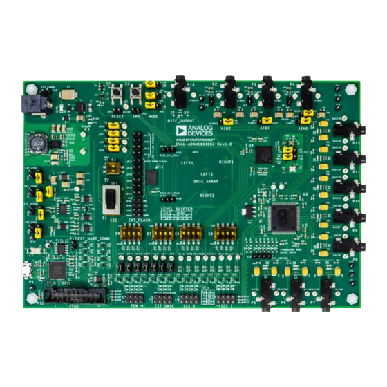
EVAL-ADAU1861EBZ BOARD PHOTOGRAPH
PLEASE SEE THE LAST PAGE FOR AN IMPORTANT
WARNING AND LEGAL TERMS AND CONDITIONS.
User Guide | EVAL-ADAU1861
The EVAL-ADAU1861EBZ can be powered by the USB bus or by
a single 12 V supply. Any of these supplies are regulated to the
voltages required on the EVAL-ADAU1861EBZ.
The printed circuit board (PCB) of the EVAL-ADAU1861EBZ is a
4-layer design, with a ground plane and a power plane on the inner
layers. The EVAL-ADAU1861EBZ contains connectors for external
microphones and speakers. The main clock of ADAU1861 can be
provided externally or by the on-board 24.576 MHz oscillator or
crystal.
The EVAL-ADAU1861EBZ contains a microphone array, aim for
beamforming. A 16-channel, high performance, 192 kHz, 24-bit
digital-to-analog converter (DAC) is used as the analog output for
audio tuning. For compatibility with 3.3 V inputs and outputs, all
digital audio interfaces can be transferred to 3.3 V inputs and
outputs from 1.8 V with a level shifter.
For full details on the ADAU1861, see the ADAU1861 data sheet,
which must be consulted with this user guide when using the
EVAL-ADAU1861EBZ evaluation board.
Figure 1. EVAL-ADAU1861EBZ Board Photograph
UG-2062
Rev. 0 | 1 of 24
Advertisement
Table of Contents

Related Manuals for Analog Devices EVAL-ADAU1861


Summary of Contents for Analog Devices EVAL-ADAU1861
-
Page 1: Evaluation Kit Contents
For full details on the ADAU1861, see the ADAU1861 data sheet, ADAU1861. The ADAU1861 core is controlled by Analog Devices, which must be consulted with this user guide when using the Inc., Lark Studio graphical user interface (GUI) software, which... -
Page 2: Table Of Contents
User Guide EVAL-ADAU1861 TABLE OF CONTENTS Evaluation Kit Contents......... 1 Connecting the Audio Cables......5 Documents Needed..........1 Creating a Basic Signal Flow......5 Software Needed...........1 Using the Evaluation Board........8 General Description..........1 Power Supply............. 8 EVAL-ADAU1861EBZ Board Photograph..... 1 Control Port............9 EVAL-ADAU1861EBZ Block Diagram.... -
Page 3: Eval-Adau1861Ebz Block Diagram
User Guide EVAL-ADAU1861 EVAL-ADAU1861EBZ BLOCK DIAGRAM Figure 2. EVAL-ADAU1861EBZ Block Diagram analog.com Rev. 0 | 3 of 24... -
Page 4: Setting Up The Eval-Adau1861Ebz Evaluation Board
User Guide EVAL-ADAU1861 SETTING UP THE EVAL-ADAU1861EBZ EVALUATION BOARD INSTALLING THE LARK STUDIO SOFTWARE INSTALLING THE USB DRIVERS Take the following steps to download and install the latest version of If the USB interface is not recognized by the Lark Studio GUI... -
Page 5: Setting Up Communication In Software
User Guide EVAL-ADAU1861 SETTING UP COMMUNICATION IN SOFTWARE 1. Download and install Lark Studio from www.ana- POWERING UP THE EVAL-ADAU1861EBZ log.com/ADAU1861. EVALUATION BOARD 2. Double click the Lark Studio shortcut on the PC desktop. 3. Go to the Project and select New Project from the dropdown... - Page 6 User Guide EVAL-ADAU1861 SETTING UP COMMUNICATION IN SOFTWARE Configure the Register Control, FastDSP, and EQ settings on 2. With the default 24.576 MHz oscillator on board, within the left navigation panel. Lark Register Control has multiple tabs the Clock tab, select MCLK_FREQ_24P576 within the that control different sections of the ADAU1861.
- Page 7 User Guide EVAL-ADAU1861 SETTING UP COMMUNICATION IN SOFTWARE If FastDSP is required in the project, a schematic must be created 1. Select EQ in the navigation panel. with the desired path for the ADAU1861 as follows: 2. Select the filter numbers and relative filter parameters.
-
Page 8: Using The Evaluation Board
User Guide EVAL-ADAU1861 USING THE EVALUATION BOARD A buck or boost DC-DC converter (LTC3115EDHD-1#PBF) with POWER SUPPLY ► a 7 V output. The three ways to supply power to the EVAL-ADAU1861EBZ in- An LDO regulator circuit (LT3042IMSE#TRPBF) that provides a ►... -
Page 9: Control Port
User Guide EVAL-ADAU1861 USING THE EVALUATION BOARD CONTROL PORT The EVAL-ADAU1861EBZ is configured to SPI mode by default. It also supports I2C and UART communications. Detailed connection and jumpers please refer to Table Table 3. Control Port Jumper and Switch (S1) Settings... -
Page 10: Codec System
User Guide EVAL-ADAU1861 USING THE EVALUATION BOARD CODEC SYSTEM Table 5. ADAU1966A Configurations (Continued) Mode Resistor Installed Resistor Uninstalled Clock Option Standalone The EVAL-ADAU1861EBZ has three options for providing a main Main clock to the ADAU1861. The default option is to use the on-board Subordinate 24.576 MHz oscillator. -
Page 11: Serial Audio Interface
User Guide EVAL-ADAU1861 USING THE EVALUATION BOARD Table 7. DAC Output Interfaces and Signal (Continued) SERIAL AUDIO INTERFACE Chip Number Function Pin Number and Px Value Serial audio signals in I S, left-justified, right-justified, and TDM DAC14P Pin 2 of P11... -
Page 12: Hardware Description
User Guide EVAL-ADAU1861 HARDWARE DESCRIPTION JUMPERS Table 10 lists the connector and jack descriptions. Table 10. Connector and Jack Description Reference Designator Functional Name Description USB interface USB +5 V power and communication with GUI. Analog Input 2 Default differential-input, 3.5 mm jack. - Page 13 User Guide EVAL-ADAU1861 HARDWARE DESCRIPTION Table 10. Connector and Jack Description (Continued) Reference Designator Functional Name Description JP10 RESET option The FT4232HQ-REEL sends the reset signal to the ADAU1861BCSZ and the ADAU1966A. Note that the default is floating if the jumper is connected. Use S2 to reset the ADAU1861BCSZ and the ADAU1966A.
-
Page 14: Evaluation Board Schematics
User Guide EVAL-ADAU1861 EVALUATION BOARD SCHEMATICS Figure 7. EVAL-ADAU1861EBZ Schematic, Page 1 analog.com Rev. 0 | 14 of 24... - Page 15 User Guide EVAL-ADAU1861 EVALUATION BOARD SCHEMATICS Figure 8. EVAL-ADAU1861EBZ Schematic, Page 2 analog.com Rev. 0 | 15 of 24...
- Page 16 User Guide EVAL-ADAU1861 EVALUATION BOARD SCHEMATICS Figure 9. EVAL-ADAU1861EBZ Schematic, Page 3 analog.com Rev. 0 | 16 of 24...
- Page 17 User Guide EVAL-ADAU1861 EVALUATION BOARD SCHEMATICS Figure 10. EVAL-ADAU1861EBZ Schematic, Page 4 analog.com Rev. 0 | 17 of 24...
- Page 18 User Guide EVAL-ADAU1861 EVALUATION BOARD SCHEMATICS Figure 11. EVAL-ADAU1861EBZ Schematic, Page 5 analog.com Rev. 0 | 18 of 24...
- Page 19 User Guide EVAL-ADAU1861 EVALUATION BOARD SCHEMATICS Figure 12. EVAL-ADAU1861EBZ Schematic, Page 6 analog.com Rev. 0 | 19 of 24...
- Page 20 User Guide EVAL-ADAU1861 EVALUATION BOARD SCHEMATICS Figure 13. EVAL-ADAU1861EBZ Schematic, Page 7 analog.com Rev. 0 | 20 of 24...
-
Page 21: Ordering Information
HPOUTP, MCLKO, MO, MP0, MP1, MP2, MP22, MP23, MP24, MP25, SCL, SDA, SDI0, SDI1, SDO0, SDO1, TP1 Microprocessors supervisory circuit in 4-Lead SOT-143, Analog Devices, Inc. ADM811TARTZ-REEL7 C1, C6, C8, C9, C10, C12, C14, 0.1 µF ceramic capacitors, 16 V, 10%, X7R, 0402, Murata... - Page 22 User Guide EVAL-ADAU1861 ORDERING INFORMATION Table 11. Bill of Materials (Continued) Components Description Manufacturer Manufacturer Number C52, C53, C76 to C89 100 µF tantalum capacitors, 6.3 V, 10%, 3528-20 AVX Corporation TAJB107K006RNJ 5600 pF ceramic capacitor, 25 V, 10%, X7R, 0402...
- Page 23 U7, U23 to U36 IC, transistor-to-transistor logic (TTL) translator 1- NEXPERIA 74AVC1T45GN,132 channel bidirectional IC, 16-channel, high performance, 192 kHz, 24-bit DAC Analog Devices ADAU1966AWBSTZ IC, 20 V, 200 mA, ultra-low noise, ultra-high power- Analog Devices LT3042IMSE#TRPBF supply rejection ratio (PSRR) RF linear regulator...
- Page 24 Evaluation Board until you have read and agreed to the Agreement. Your use of the Evaluation Board shall signify your acceptance of the Agreement. This Agreement is made by and between you (“Customer”) and Analog Devices, Inc. (“ADI”), with its principal place of business at Subject to the terms and conditions of the Agreement, ADI hereby grants to Customer a free, limited, personal, temporary, non-exclusive, non-sublicensable, non-transferable license to use the Evaluation Board FOR EVALUATION PURPOSES ONLY.
Need help?
Do you have a question about the EVAL-ADAU1861 and is the answer not in the manual?
Questions and answers