Table of Contents
Advertisement
Quick Links
Evaluating the ADAQ23876/ADAQ23878 16-/18-Bit, 15 MSPS, µModule Data Acquisition Solutions
FEATURES
Evaluation boards for
ADAQ23876
►
15 MSPS, µModule data acquisition solutions
Versatile analog signal conditioning circuitry
►
On-board reference, LDO, and power supply circuits
►
PC software for control and data analysis of time and frequency
►
domain
System demonstration platform-compatible (SDP-H1)
►
EVALUATION BOARD KIT CONTENTS
EVAL-ADAQ23876FMCZ or EVAL-ADAQ23878FMCZ evaluation
►
board
EQUIPMENT NEEDED
®
PC running Windows
10 or higher
►
SDP-H1 (EVAL-SDP-CH1Z) controller board
►
Low noise, precision signal source (such as the SYS-2700 ser-
►
ies)
Standard USB A to USB mini-B
►
Band-pass filter suitable for 18-bit testing (value based on signal
►
frequency)
SOFTWARE NEEDED
ADAQ23876 or ADAQ23878
►
SDP-H1 driver
►
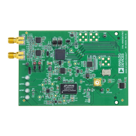
EVALUATION BOARD PHOTOGRAPH
Analog Devices is in the process of updating documentation to provide terminology and language that is culturally appropriate. This is a process
with a wide scope and will be phased in as quickly as possible. Thank you for your patience.
PLEASE SEE THE LAST PAGE FOR AN IMPORTANT
WARNING AND LEGAL TERMS AND CONDITIONS.
User Guide | EVAL-ADAQ23876/EVAL-
and ADAQ23878, 16-/18-bit,
ACE
plugin
GENERAL DESCRIPTION
The EVAL-ADAQ23876FMCZ and EVAL-ADAQ23878FMCZ eval-
uation boards (see
Figure
the ADAQ23876 and ADAQ23878 15 MSPS, 16-/18-bit, high
speed, precision µModule
The EVAL-ADAQ23876FMCZ and EVAL-ADAQ23878FMCZ dem-
onstrate the performance of the ADAQ23876 and ADAQ23878
µModules, respectively, and are versatile tools for a variety of
applications.
The ADAQ23876 and ADAQ23878 µModules combine multiple
common signal processing and conditioning blocks into devices
that include a low noise, fully differential analog-to-digital converter
(ADC) driver, a stable reference buffer, high resolution, 16-/18-bit,
15 MSPS successive approximation register (SAR) ADCs, and the
critical passive components necessary for optimum performance.
The EVAL-ADAQ23876FMCZ and EVAL-ADAQ23878FMCZ inter-
face with a high speed system demonstration platform (SDP),
SDP-H1 (EVAL-SDP-CH1Z), via a 160-pin connector, as shown in
Figure
2.
For full details on the ADAQ23876 and ADAQ23878, see the
ADAQ23876 and ADAQ23878 data sheets, which must be con-
sulted in conjunction with this user guide when using the EVAL-
ADAQ23876FMCZ or EVAL-ADAQ23878FMCZ.
Figure 1.
ADAQ23878
UG-2023
1) enable simplified evaluation of
®
data acquisition solutions, respectively.
Rev. A | 1 of 29
Advertisement
Table of Contents

Subscribe to Our Youtube Channel
Related Manuals for Analog Devices EVAL-ADAQ23876FMCZ


Summary of Contents for Analog Devices EVAL-ADAQ23876FMCZ
-
Page 1: Features
Figure 1. Analog Devices is in the process of updating documentation to provide terminology and language that is culturally appropriate. This is a process with a wide scope and will be phased in as quickly as possible. Thank you for your patience. -
Page 2: Table Of Contents
Exiting the Software..........11 Equipment Needed..........1 Description of Analysis Window ...... 11 Software Needed...........1 Troubleshooting........... 17 General Description..........1 Connecting the EVAL-ADAQ23876FMCZ or Evaluation Board Photograph........1 EVAL-ADAQ23878FMCZ and the SDP-H1 Evaluation Board Hardware........3 to the PC............17 Setting Up the Evaluation Board ....... 3 Verifying the Board Connection......17... -
Page 3: Evaluation Board Hardware
ADAQ23876FMCZ and EVAL-ADAQ23878FMCZ are powered by to the SDP-H1 controller board. The board consists of one µModule a 3.3 V rail coming from the SDP-H1. The EVAL-ADAQ23876FMCZ (U1, ADAQ23878 or ADAQ23876), a choice of a 4.096 V reference and EVAL-ADAQ23878FMCZ can be powered from an external (U5, LTC6655) or 2.048V reference (U3, ADR4520), on-board pow-... -
Page 4: Link Configuration Options
Table 2 shows the presents a 4.096 V on the REFBUF pin and a buffered 2.048 default positions of the links for the EVAL-ADAQ23876FMCZ and V (midscale) of the fully differential ADC driver amplifier (FDA)'s EVAL-ADAQ23878FMCZ. VCMO pin of the ADAQ23876 and ADAQ23878. -
Page 5: Evaluation Board Connectors
Table 4 Table 5). There are several test points and single in line (SIL) headers on the EVAL-ADAQ23876FMCZ and EVAL-ADAQ23878FMCZ. These test points provide easy access to on-board signals for troubleshooting and evaluation purposes. Table 3 details the different gain positions for the links of the Figure 5. - Page 6 User Guide EVAL-ADAQ23876/EVAL-ADAQ23878 EVALUATION BOARD HARDWARE Table 5. 160-Pin FMC Connector (P5) Details Signals Function OSC_CLK+ 100 MHz low jitter positive line of differential pair for carrying clock signals from the daughter board. OSC_CLK− 100 MHz low jitter negative line of differential pair for carrying clock signals from the daughter board. 1, 2 CLK±...
-
Page 7: Software Installation
ACE. ACE is a desktop software application allowing the evaluation and control of multiple evaluation systems across the Analog Devices, Inc., product portfolio. The installation process consists of the ACE software installation and the SDP-H1 driver installation. - Page 8 User Guide EVAL-ADAQ23876/EVAL-ADAQ23878 SOFTWARE INSTALLATION Figure 11. Choose Components Figure 13. Installation in Progress 8. The Windows Security window opens (see Figure 12). Click 9. When the installation is complete, click Next > (see Figure 14), Install. The installation is in progress. No action is required and then click Finish to complete the installation process.
-
Page 9: Launching The Software
3. Double click the ADAQ23876 Board or ADAQ23878 Board 1. From the Start menu, select All Programs > Analog Devices icon to open the board view window. > ACE > ACE.exe to open the ACE software main shown Figure 15. - Page 10 User Guide EVAL-ADAQ23876/EVAL-ADAQ23878 SOFTWARE OPERATION Figure 16. Chip View Figure 17. Analysis View analog.com Rev. A | 10 of 29...
-
Page 11: Exiting The Software
User Guide EVAL-ADAQ23876/EVAL-ADAQ23878 SOFTWARE OPERATION EXITING THE SOFTWARE DESCRIPTION OF ANALYSIS WINDOW To exit the software, click the file icon on the upper right tab Click Proceed to Analysis in the chip view window to open the and then click Exit. analysis view window shown in Figure 17. - Page 12 User Guide EVAL-ADAQ23876/EVAL-ADAQ23878 SOFTWARE OPERATION Figure 19. Histogram Tab Figure 20. FFT Tab analog.com Rev. A | 12 of 29...
- Page 13 User Guide EVAL-ADAQ23876/EVAL-ADAQ23878 SOFTWARE OPERATION The data Waveform graph shows each successive sample of the Waveform Tab µModule output. The user can zoom in on and pan across the The Waveform tab displays results in the time domain, as shown in Waveform graph using the embedded waveform tools.
- Page 14 To perform a linearity test, apply a sinusoidal signal with 0.5 INL Tab and DNL Tab dB above full scale to the EVAL-ADAQ23876FMCZ or EVAL- The INL tab and DNL tab display linearity analysis. INL is the ADAQ23878FMCZ at the VIN+ and VIN− SMA inputs. Set the deviation of each individual code from a line drawn from negative number of hits per code and adjust to the desired accuracy.
- Page 15 User Guide EVAL-ADAQ23876/EVAL-ADAQ23878 SOFTWARE OPERATION Figure 22. INL Tab Figure 23. DNL Tab analog.com Rev. A | 15 of 29...
- Page 16 User Guide EVAL-ADAQ23876/EVAL-ADAQ23878 SOFTWARE OPERATION ANALYSIS Pane RESULTS Pane The General Settings section allows the user to set up the prefer- The Signal section displays the sample frequency, fundamental fre- red configuration of the FFT analysis. This configuration sets how quency (Fund Frequency), and fundamental power (Fund Power).
-
Page 17: Troubleshooting
4. If the SDP-H1 driver software is installed and the board is CNV± or CLK±, and the DA± and DB± digital outputs must not run connected to the PC properly, Analog Devices SDP-H1 ap- near or cross over analog signal paths to prevent noise coupling to pears under ADI Development Tools in the Device Manager the ADAQ23876 and ADAQ23878. -
Page 18: Mechanical Stress
User Guide EVAL-ADAQ23876/EVAL-ADAQ23878 TROUBLESHOOTING the μModule supply rails (VDD, VIO, VS+, and VS−) to GND to MECHANICAL STRESS minimize electromagnetic interference (EMI) susceptibility and to The mechanical stress of mounting a device to a board can cause reduce the effect of glitches on the power supply lines. All the other subtle changes to the SNR and internal voltage reference. -
Page 19: Evaluation Board Schematics And Silkscreens
User Guide EVAL-ADAQ23876/EVAL-ADAQ23878 EVALUATION BOARD SCHEMATICS AND SILKSCREENS Figure 25. EVAL-ADAQ23876FMCZ and EVAL-ADAQ23878FMCZ Board Schematic, Power Supplies analog.com Rev. A | 19 of 29... - Page 20 User Guide EVAL-ADAQ23876/EVAL-ADAQ23878 EVALUATION BOARD SCHEMATICS AND SILKSCREENS Figure 26. EVAL-ADAQ23876FMCZ and EVAL-ADAQ23878FMCZ Board Schematic, Input Signal Path analog.com Rev. A | 20 of 29...
- Page 21 User Guide EVAL-ADAQ23876/EVAL-ADAQ23878 EVALUATION BOARD SCHEMATICS AND SILKSCREENS Figure 27. EVAL-ADAQ23876FMCZ and EVAL-ADAQ23878FMCZ Board Schematic, External Clock analog.com Rev. A | 21 of 29...
- Page 22 User Guide EVAL-ADAQ23876/EVAL-ADAQ23878 EVALUATION BOARD SCHEMATICS AND SILKSCREENS Figure 28. EVAL-ADAQ23876FMCZ and EVAL-ADAQ23878FMCZ Board Schematic, FMC Connector and External Supplies analog.com Rev. A | 22 of 29...
- Page 23 User Guide EVAL-ADAQ23876/EVAL-ADAQ23878 EVALUATION BOARD SCHEMATICS AND SILKSCREENS Figure 29. EVAL-ADAQ23876FMCZ and EVAL-ADAQ23878FMCZ Board Primary Silkscreen Figure 30. EVAL-ADAQ23876FMCZ and EVAL-ADAQ23878FMCZ Board Primary Layer, L1 analog.com Rev. A | 23 of 29...
- Page 24 User Guide EVAL-ADAQ23876/EVAL-ADAQ23878 EVALUATION BOARD SCHEMATICS AND SILKSCREENS Figure 31. EVAL-ADAQ23876FMCZ and EVAL-ADAQ23878FMCZ Board Ground Layer, L2 Figure 32. EVAL-ADAQ23876FMCZ and EVAL-ADAQ23878FMCZ Board Power Layer, L3 analog.com Rev. A | 24 of 29...
- Page 25 User Guide EVAL-ADAQ23876/EVAL-ADAQ23878 EVALUATION BOARD SCHEMATICS AND SILKSCREENS Figure 33. EVAL-ADAQ23876FMCZ and EVAL-ADAQ23878FMCZ Board Bottom Layer, L4 Figure 34. EVAL-ADAQ23876FMCZ and EVAL-ADAQ23878FMCZ Board Secondary Silkscreen analog.com Rev. A | 25 of 29...
- Page 26 User Guide EVAL-ADAQ23876/EVAL-ADAQ23878 EVALUATION BOARD SCHEMATICS AND SILKSCREENS Figure 35. EVAL-ADAQ23876FMCZ and EVAL-ADAQ23878FMCZ Board Drill Chart and Size 69 mm × 100.5 mm analog.com Rev. A | 26 of 29...
-
Page 27: Ordering Information
+4899, −4899 Connector PCB test points, red 5000 Keystone Electronics A2, A3 Unity-gain stable, ultralow distortion ADA4899-1YRDZ Analog Devices C1, C2, C9, C47 2.2 μF ceramic capacitors, X5R, general-purpose GRM188R61H225KE11J Murata C3, C4, C7, C10 0.1 μF ceramic capacitors, X7R, 0603 06035C104KAT2A 0.01 μF multilayer ceramic capacitor, X7R, automotive... - Page 28 2.4 kΩ resistor precision thick film chip, 0603 ERJ-3EKF2401V Panasonic Transformer RF1:1 MABA-007159-000000 Macom Technology Solutions 16-/18-bit, 15 MSPS, μModule data acquisition solutions ADAQ23876BBCZ/ Analog Devices ADAQ23878BBCZ D-type positive edge NL17SZ74USG ON Semiconductor Low voltage dual supply, 2-bit signal translator FXL2TD245L10X...
-
Page 29: Notes
Evaluation Board until you have read and agreed to the Agreement. Your use of the Evaluation Board shall signify your acceptance of the Agreement. This Agreement is made by and between you (“Customer”) and Analog Devices, Inc. (“ADI”), with its principal place of business at Subject to the terms and conditions of the Agreement, ADI hereby grants to Customer a free, limited, personal, temporary, non-exclusive, non-sublicensable, non-transferable license to use the Evaluation Board FOR EVALUATION PURPOSES ONLY.
Need help?
Do you have a question about the EVAL-ADAQ23876FMCZ and is the answer not in the manual?
Questions and answers