Table of Contents
Advertisement
Quick Links
Evaluating the ADAQ7768-1 24-Bit, Single-Channel Precision μModule Data Acquisition System
FEATURES
Evaluation kit for ADAQ7768-1 24-bit single-channel precision
►
®
μModule
data acquisition system
Switch or GPIO controlled gain mode
►
Complete power management solution
►
FMC connector to FPGA for digital interface
►
Optional Arduino and PMOD connector
►
EVALUATION KIT CONTENTS
EV-ADAQ7768-1FMC1Z evaluation board
►
EQUIPMENT NEEDED
SDP-H1
(EVAL-SDP-CH1Z) system demonstration platform
►
DC/AC signal source (audio precision or similar high perform-
►
ance signal source)
PC running Microsoft Windows 7, 8, or 10 with USB 2.0 port
►
SOFTWARE NEEDED
Analysis, control, evaluation (ACE)
►
ADAQ7768-1 ACE plugin
►
PLEASE SEE THE LAST PAGE FOR AN IMPORTANT
WARNING AND LEGAL TERMS AND CONDITIONS.
software
User Guide | EVAL-ADAQ7768-1
GENERAL DESCRIPTION
The EV-ADAQ7768-1FMC1Z evaluation kit features the
ADAQ7768-1, a 24-bit, single-channel precision μModule
acquisition (DAQ) system. The evaluation board demonstrates the
performance of the ADAQ7768-1 μModule and is a versatile tool for
a variety of applications.
The EV-ADAQ7768-1FMC1Z board connects to the USB port of the
PC through the system demonstration platform (SDP-H1). By de-
fault, all the necessary supply rails on the EV-ADAQ7768-1FMC1Z
are powered by a 3.3 V rail coming from the SDP-H1. The 3.3 V rail
is regulated by the on-board power solution to ±15 V and 5.3 V to
power the ADAQ7768-1 and its support components.
The EV-ADAQ7768-1FMC1Z is used alongside a downloadable
evaluation software (ACE) that fully configures the ADAQ7768-1
device register functionality, and also provides DC and AC time
and frequency domain analysis in the form of waveform graphs,
histograms, and associated noise analysis for ADC performance
evaluation. The ACE software controls the EV-ADAQ7768-1FMC1Z
over the USB through the system demonstration platform (SDP-
H1).
The
ADAQ7768-1
data sheet provides a full description and com-
plete specifications of the ADAQ7768-1. Consult it in conjunction
with this user guide when using the evaluation board. Full details on
the SDP-H1 are available on the SDP-H1 product page.
UG-1906
®
data
Rev. 0 | 1 of 33
Advertisement
Table of Contents

Related Manuals for Analog Devices EVAL-ADAQ7768-1


Summary of Contents for Analog Devices EVAL-ADAQ7768-1
-
Page 1: Features
User Guide | EVAL-ADAQ7768-1 UG-1906 Evaluating the ADAQ7768-1 24-Bit, Single-Channel Precision μModule Data Acquisition System FEATURES GENERAL DESCRIPTION Evaluation kit for ADAQ7768-1 24-bit single-channel precision The EV-ADAQ7768-1FMC1Z evaluation kit features the ► ® ® μModule data acquisition system ADAQ7768-1, a 24-bit, single-channel precision μModule data acquisition (DAQ) system. -
Page 2: Table Of Contents
User Guide EVAL-ADAQ7768-1 TABLE OF CONTENTS Features..............1 Hardware Link Options........8 Evaluation Kit Contents......... 1 Evaluation Board Software........10 Equipment Needed..........1 Launching the Software........10 Software Needed...........1 Start-up Sequence........... 10 General Description..........1 Description of the Analysis Window....10 Evaluation Board Photograph........3 Exiting the Software..........11... -
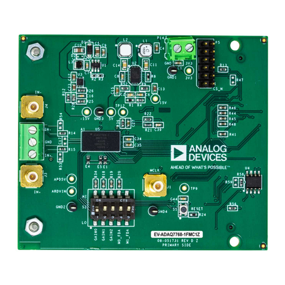
Page 3: Evaluation Board Photograph
User Guide EVAL-ADAQ7768-1 EVALUATION BOARD PHOTOGRAPH Figure 1. Evaluation Board Photograph analog.com Rev. 0 | 3 of 33... -
Page 4: Getting Started
Download also the ADAQ7768-1 ACE plugin from the plugin manager, or from the EV-ADAQ7768-1FMC1Z product page. ACE is a desktop software application that evaluates and controls multiple evaluation systems across the Analog Devices product portfolio. The installation process consists of the ACE software installation and SDP-H1 driver installation. -
Page 5: Evaluation Board Setup
User Guide EVAL-ADAQ7768-1 GETTING STARTED EVALUATION BOARD SETUP The EV-ADAQ7768-1FMC1Z connects to the SDP-H1. The SDP- H1 board serves as the communication link between the PC and EV-ADAQ7768-1FMC1Z. Figure 11 shows the connections between the EV-ADAQ7768-1FMC1Z and SDP-H1 board. Connecting the EV-ADAQ7768-1FMC1Z and SDP-H1 to a PC Figure 6. - Page 6 User Guide EVAL-ADAQ7768-1 GETTING STARTED Figure 9. Evaluation Board Connection Verifying the Board Connection After completing Software Installation Procedures Evaluation Board Setup, follow these steps to verify the board connection: 1. Run the Found New Hardware Wizard after the SDP-H1 system demonstration platform board is plugged into the PC.
-
Page 7: Evaluation Board Hardware
User Guide EVAL-ADAQ7768-1 EVALUATION BOARD HARDWARE Figure 11. Simplified Evaluation Board Block Diagram HARDWARE OVERVIEW Figure 11 shows the simplified evaluation board block diagram POWER SUPPLIES of EVAL-ADAQ7768-1FMC1Z connected to the SDP-H1 controller By default, the EV-ADAQ7768-1FMC1Z obtains its power from the board. -
Page 8: Analog Inputs
User Guide EVAL-ADAQ7768-1 EVALUATION BOARD HARDWARE in 0.1 μF supply decoupling capacitors on VDD_PGA, VSS_PGA, Measure the true dynamic range of the board by connecting the two VDD2_PGA, VDD_FDA, VDD_ADC, and VDD2_ADC supply pins. inputs to the board’s ground reference through the screw terminal... - Page 9 User Guide EVAL-ADAQ7768-1 EVALUATION BOARD HARDWARE Table 3. On-Board Connectors (Continued) Connector Function Terminal block connector for external 3.3 V supply. J3/J4/P7 SMB and terminal block connector for analog inputs, IN+ and IN–. ADC reset switch Mechanical switch for PGIA Gain and FDA power mode control.
-
Page 10: Evaluation Board Software
Follow these steps to launch the ACE software: is set to 256 kSPS. 1. From the Start menu, select All Programs > Analog Devices Click Run Once in the Capture Settings section to start a data > ACE > ACE.exe to open the main window shown in... -
Page 11: Exiting The Software
User Guide EVAL-ADAQ7768-1 EVALUATION BOARD SOFTWARE The histogram graph displays the number of hits per code within The Distortion section displays the harmonic content of the sam- the sampled data. This graph is useful for DC analysis and indi- pled signal, and the DC section displays the DC Power when cates the noise performance of the device. - Page 12 User Guide EVAL-ADAQ7768-1 EVALUATION BOARD SOFTWARE Figure 15. EV-ADAQ7768-1FMC1Z Chip View Figure 16. EV-ADAQ7768-1FMC1Z Analysis View analog.com Rev. 0 | 12 of 33...
- Page 13 User Guide EVAL-ADAQ7768-1 EVALUATION BOARD SOFTWARE Figure 17. EV-ADAQ7768-1FMC1Z Waveform Figure 18. EV-ADAQ7768-1FMC1Z Histogram analog.com Rev. 0 | 13 of 33...
- Page 14 User Guide EVAL-ADAQ7768-1 EVALUATION BOARD SOFTWARE Figure 19. EV-ADAQ7768-1FMC1Z FFT analog.com Rev. 0 | 14 of 33...
-
Page 15: Configuring The Board And The Adaq7768-1
User Guide EVAL-ADAQ7768-1 CONFIGURING THE BOARD AND THE ADAQ7768-1 INPUT RANGE CONTROL Table 4. Configuration Switch (S2) Functions Name Description There are two ways to control the ADAQ7768-1 input range. GAIN0, GAIN1, 1. Through the GPIO of ADAQ7768-1, controlled over the SPI. -
Page 16: Data Capture
User Guide EVAL-ADAQ7768-1 CONFIGURING THE BOARD AND THE ADAQ7768-1 Figure 21. Input Range Through Mechanical Switch (S2) etc. are evaluated. Perform the following steps for AC measure- DATA CAPTURE ment: The ADAQ7768-1 has excellent performance in both AC and DC 1. - Page 17 User Guide EVAL-ADAQ7768-1 CONFIGURING THE BOARD AND THE ADAQ7768-1 Figure 22. FFT Plot for a Typical AC Measurement, with AFE_GAIN = 1.3 V/V (Gain 2 Mode), Differential Input of 2.98 Vp (-0.5 dBFS) 1 kHz, ODR = 256 kSPS, 32768 Samples samples at 50 SPS takes 8192 ×...
- Page 18 User Guide EVAL-ADAQ7768-1 CONFIGURING THE BOARD AND THE ADAQ7768-1 Figure 23. Set the Digital Filter Type Figure 24. Set the Sinc3 Filter Decimation Ratio analog.com Rev. 0 | 18 of 33...
- Page 19 User Guide EVAL-ADAQ7768-1 CONFIGURING THE BOARD AND THE ADAQ7768-1 Figure 25. Sinc3 Filter Decimation Ratio Using Memory Map View Figure 26. Change the Number of Samples to Collect Per Sample Run analog.com Rev. 0 | 19 of 33...
- Page 20 User Guide EVAL-ADAQ7768-1 CONFIGURING THE BOARD AND THE ADAQ7768-1 Figure 27. FFT Plot for a Typical DC Measurement, with AFE_GAIN = 20.8 V/V (Gain 6 Mode), Inputs Shorted, ODR = 50 SPS, 1024 Samples Figure 28. Histogram of Output Codes, with AFE_GAIN = 20.8 V/V (Gain 6 Mode), Inputs Shorted, ODR = 50 SPS, 1024 Samples...
-
Page 21: Reset Switches
User Guide EVAL-ADAQ7768-1 CONFIGURING THE BOARD AND THE ADAQ7768-1 Write the equivalent hexadecimal value of 5119 to sinc3 decimation RESET SWITCHES registers. Refer to the ADAQ7768-1 data sheet for more information Press S1 to reset the ADAQ7768-1. Resetting the ADAQ7768-1 on the register configuration. -
Page 22: Evaluation Board Schematic
User Guide EVAL-ADAQ7768-1 EVALUATION BOARD SCHEMATIC Figure 29. Evaluation Board Schematic 1 analog.com Rev. 0 | 22 of 33... - Page 23 User Guide EVAL-ADAQ7768-1 EVALUATION BOARD SCHEMATIC Figure 30. Evaluation Board Schematic 2 analog.com Rev. 0 | 23 of 33...
-
Page 24: Evaluation Board Layout
User Guide EVAL-ADAQ7768-1 EVALUATION BOARD LAYOUT Figure 31. Silkscreen Primary analog.com Rev. 0 | 24 of 33... - Page 25 User Guide EVAL-ADAQ7768-1 EVALUATION BOARD LAYOUT Figure 32. L1 Primary Layer analog.com Rev. 0 | 25 of 33...
- Page 26 User Guide EVAL-ADAQ7768-1 EVALUATION BOARD LAYOUT Figure 33. L2 Ground Layer analog.com Rev. 0 | 26 of 33...
- Page 27 User Guide EVAL-ADAQ7768-1 EVALUATION BOARD LAYOUT Figure 34. L3 Power Layer analog.com Rev. 0 | 27 of 33...
- Page 28 User Guide EVAL-ADAQ7768-1 EVALUATION BOARD LAYOUT Figure 35. L4 Bottom Layer analog.com Rev. 0 | 28 of 33...
- Page 29 User Guide EVAL-ADAQ7768-1 EVALUATION BOARD LAYOUT Figure 36. Finish Holes and Board Size analog.com Rev. 0 | 29 of 33...
-
Page 30: Ordering Information
User Guide EVAL-ADAQ7768-1 ORDERING INFORMATION BILL OF MATERIALS Table 6. Bill of Materials Quantity Designator Description Value Manufacturer Manufacturer Part Number 180 MHz rail-to-rail input Not applicable Analog Devices ADA4807-1ARJZ-R7 output amplifier C1, C9, C35, C38 Ceramic capacitors, X7R, 1 μF... - Page 31 User Guide EVAL-ADAQ7768-1 ORDERING INFORMATION Table 6. Bill of Materials (Continued) Quantity Designator Description Value Manufacturer Manufacturer Part Number PCB connector, high Not applicable Samtec TSW-106-08-G-D dynamic range standard male, peripheral module PCB connector, term block, Not applicable Phoenix Contact...
- Page 32 User Guide EVAL-ADAQ7768-1 ORDERING INFORMATION Table 6. Bill of Materials (Continued) Quantity Designator Description Value Manufacturer Manufacturer Part Number acquisition system, preliminary Ultra-low noise, low- Not applicable Analog Devices ADR444BRZ dropout XFET voltage references with current sink and source analog.com...
- Page 33 Evaluation Board until you have read and agreed to the Agreement. Your use of the Evaluation Board shall signify your acceptance of the Agreement. This Agreement is made by and between you (“Customer”) and Analog Devices, Inc. (“ADI”), with its principal place of business at Subject to the terms and conditions of the Agreement, ADI hereby grants to Customer a free, limited, personal, temporary, non-exclusive, non-sublicensable, non-transferable license to use the Evaluation Board FOR EVALUATION PURPOSES ONLY.
Need help?
Do you have a question about the EVAL-ADAQ7768-1 and is the answer not in the manual?
Questions and answers