Table of Contents
Advertisement
Quick Links
Evaluating the ADAQ4001/ADAQ4003 16-/18-Bit, 2 MSPS, µModule Data Acquisition Solution
FEATURES
Fully featured Pmod evaluation board with a Pmod to FMC inter-
►
poser board
Versatile analog signal conditioning circuitry
►
On-board reference and ADC drivers
►
PC software for control and data analysis of time and frequency
►
domain
System demonstration platform compatible (EVAL-SDP-CH1Z)
►
EVALUATION BOARD KIT CONTENTS
EVAL-ADAQ4001PMDZ
or
►
ation board
EVAL-PMD-IB1Z Pmod to FMC interposer board
►
EQUIPMENT NEEDED
®
PC running Windows
10 or higher
►
EVAL-SDP-CH1Z (SDP-H1) controller board
►
Precision signal source
►
Cable (SMB input to evaluation board)
►
Standard USB A to Mini-B USB cable
►
Band-pass filter suitable for 16-bit/18-bit testing (value based on
►
signal frequency)
SOFTWARE NEEDED
ACE
evaluation software
►
ADAQ4001
or
ADAQ4003 ACE plugin
►
PLEASE SEE THE LAST PAGE FOR AN IMPORTANT
WARNING AND LEGAL TERMS AND CONDITIONS.
EVAL-ADAQ4001FMCZ/EVAL-ADAQ4003FMCZ User Guide
EVAL-ADAQ4003PMDZ
Pmod evalu-
User Guide | UG-1533
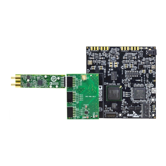
GENERAL DESCRIPTION
The ADAQ4001 and ADAQ4003 µModule
evaluation kit (EVAL-ADAQ4001FMCZ or EVAL-ADAQ4003FMCZ)
contains the EVAL-ADAQ4001PMDZ or EVAL-ADAQ4003PMDZ
peripheral module (Pmod) board and the EVAL-PMD-IB1Z Pmod
to field programmable grid array (FPGA) mezzanine card (FMC)
interposer board that interfaces with the system demonstration
controller board (EVAL-SDP-CH1Z) via a 160-pin FMC connector,
as shown in
Figure
1.
The ADAQ4001 µModule and ADAQ4003 µModule combine multi-
ple common signal processing and conditioning blocks into a single
device that includes a low noise, fully differential analog-to-digital
converter (ADC) driver, a stable reference buffer, a high resolution,
16-bit or 18-bit, 2 MSPS successive approximation register (SAR)
ADC, and the critical passive components necessary for optimum
performance.
The EVAL-ADAQ4001PMDZ and EVAL-ADAQ4003PMDZ on-board
components include the following:
The
ADR4550
high precision, buffered band gap, 5.0 V voltage
►
reference (see
Figure
25)
An optional
ADA4898-1
high voltage, low noise, low distortion,
►
unity-gain stable, high speed op amp (see
An optional
AD8251
programmable gain in-amp (see
►
The
LT5400-4
quad matched, low drift, resistor network
►
Note that J1 and J2 on the EVAL-ADAQ4001PMDZ and EVAL-
ADAQ4003PMDZ provide low noise analog signal sources.
For full details on the ADAQ4001 or ADAQ4003, see the
ADAQ4001 or ADAQ4003 data sheet, which must be consult-
ed in conjunction with this user guide when using the EVAL-
ADAQ4001FMCZ or EVAL-ADAQ4003FMCZ.
®
data acquisition system
Figure
26)
Figure
26)
Rev. A | 1 of 30
Advertisement
Table of Contents

Subscribe to Our Youtube Channel
Related Manuals for Analog Devices EVAL-ADAQ4001FMCZ


Summary of Contents for Analog Devices EVAL-ADAQ4001FMCZ
-
Page 1: Features
Fully featured Pmod evaluation board with a Pmod to FMC inter- The ADAQ4001 and ADAQ4003 µModule data acquisition system ► poser board evaluation kit (EVAL-ADAQ4001FMCZ or EVAL-ADAQ4003FMCZ) contains the EVAL-ADAQ4001PMDZ or EVAL-ADAQ4003PMDZ Versatile analog signal conditioning circuitry ► peripheral module (Pmod) board and the EVAL-PMD-IB1Z Pmod On-board reference and ADC drivers ►... -
Page 2: Table Of Contents
FFT Tab............16 Photograph............3 INL and DNL Tab..........16 Evaluation Board Hardware........4 Troubleshooting........... 18 Setting Up the EVAL-ADAQ4001FMCZ and Evaluation Board Software Troubleshooting..18 EVAL-ADAQ4003FMCZ Evaluation Kit.... 4 Hardware Troubleshooting....... 18 EVAL-SDP-CH1Z (SDP-H1) Board....4 Evaluation Board Schematics and Silkscreens... 19 Power Supplies.......... -
Page 3: Photograph
User Guide UG-1533 EVAL-ADAQ4001FMCZ OR EVAL-ADAQ4003FMCZ EVALUATION BOARD KIT PHOTOGRAPH Figure 1. analog.com Rev. A | 3 of 30... -
Page 4: Evaluation Board Hardware
User Guide UG-1533 EVALUATION BOARD HARDWARE demonstration platform (SDP-H1) to capture the data via a graphic SETTING UP THE EVAL-ADAQ4001FMCZ AND user interface (GUI) (see Figure 1). The SDP-H1 requires power EVAL-ADAQ4003FMCZ EVALUATION KIT ® ® from a 12 V wall adapter. The SDP-H1 has a Xilinx... -
Page 5: Power Supplies
EVAL-ADAQ4003PMDZ when using a benchtop power supply of SDP-H1 supplies 3.3 V to power the rails for the dif- ±15.5 V: ferent components on the EVAL-ADAQ4001FMCZ and EVAL- 1. Connect the EVAL-ADAQ4001PMDZ or EVAL- ADAQ4003FMCZ. ADAQ4003PMDZ to the EVAL-PMD-IB1Z interposer board at ADAQ4001 µModule and... -
Page 6: Analog Inputs
User Guide UG-1533 EVALUATION BOARD HARDWARE The analog inputs are fully differential by default. If a single-ended ANALOG INPUTS bipolar input is desired, such as ±10 V, the EVAL-ADAQ4001PMDZ The analog inputs of the EVAL-ADAQ4001PMDZ EVAL- or EVAL-ADAQ4003PMDZ can be configured for single-ended to ADAQ4003PMDZ, J1 and J2, are Subminiature Version B (SMB) differential conversion by changing JP6 to Pin B to Pin COM and by connectors. -
Page 7: Link Configuration For Different Gain Options
User Guide UG-1533 EVALUATION BOARD HARDWARE LINK CONFIGURATION FOR DIFFERENT GAIN OPTIONS Multiple link options must be set correctly for the appropriate gain configuration of the ADAQ4001 or ADAQ4003. Table 3 details the different gain positions for the links of the EVAL-ADAQ4001PMDZ and EVAL-ADAQ4003PMDZ. -
Page 8: Evaluation Board Software
Install the ACE software and SDP-H1 drivers before connecting Figure 9. License Agreement the EVAL-ADAQ4001FMCZ or EVAL-ADAQ4003FMCZ and the 6. Click Browse... to choose the install location and then click SDP-H1 to the USB port of the PC to ensure that the evaluation Next >... -
Page 9: Evaluation Board Setup Procedures
The EVAL-ADAQ4001FMCZ or EVAL-ADAQ4003FMCZ connects to the SDP-H1. The SDP-H1 is the communication link between the PC and the EVAL-ADAQ4001FMCZ or EVAL-ADAQ4003FMCZ. Figure 1 shows a diagram of the connections between the EVAL- ADAQ4001FMCZ or EVAL-ADAQ4003FMCZ and the SDP-H1. - Page 10 Disconnect power from the SDP-H1 or press the reset tact switch the PC, Analog Devices SDP-H1 is shown in the ADI Devel- located alongside the mini USB port on the SDP-H1 before dis-...
-
Page 11: Ace Software Operation
To make the ADAQ4001 Eval Board or ADAQ4003 Eval 6. Click the Proceed to Analysis button to show the Analysis Board icon appear, connect the EVAL-ADAQ4001FMCZ or view window, as shown in Figure EVAL-ADAQ4003FMCZ and the SDP-H1 to the USB port of the Figure 16. - Page 12 User Guide UG-1533 ACE SOFTWARE OPERATION Figure 17. Board View Window Figure 18. Chip View Window analog.com Rev. A | 12 of 30...
- Page 13 User Guide UG-1533 ACE SOFTWARE OPERATION Figure 19. Analysis View Window analog.com Rev. A | 13 of 30...
-
Page 14: Description Of Analysis View Window
User Guide UG-1533 ACE SOFTWARE OPERATION section) and analysis settings (see the ANALYSIS SETTINGS sec- DESCRIPTION OF ANALYSIS VIEW WINDOW tion). The Analysis view window allows the user to showcase the per- The Analysis view window contains the Waveform tab (see Figure formance of the ADAQ4001... - Page 15 User Guide UG-1533 ACE SOFTWARE OPERATION Figure 22. FFT Tab Click Run Once to start a data capture of the samples at the CAPTURE sample rate specified in the No. of samples pulldown menu. These The CAPTURE pane contains the capture settings. These settings samples are stored on the FPGA device and are only transferred to reflect onto the registers automatically before data capture.
-
Page 16: Waveform Tab
User Guide UG-1533 ACE SOFTWARE OPERATION The Histogram graph displays the number of hits per code within WAVEFORM TAB the sampled data. This graph is useful for dc analysis and indicates The Waveform tab displays data in form of time vs. discrete data the noise performance of the device. - Page 17 User Guide UG-1533 ACE SOFTWARE OPERATION Figure 24. DNL Tab analog.com Rev. A | 17 of 30...
-
Page 18: Troubleshooting
SDP-H1 to the PC, allow the Found New Hardware Wizard to run before starting the ACE software. 4. Power down the EVAL-ADAQ4001FMCZ or EVAL- ADAQ4003FMCZ and relaunch the ACE software. 4. If the EVAL-ADAQ4001FMCZ or EVAL-ADAQ4003FMCZ does not appear to be functioning, ensure that the EVAL- 5. -
Page 19: Evaluation Board Schematics And Silkscreens
User Guide UG-1533 EVALUATION BOARD SCHEMATICS AND SILKSCREENS EVAL-ADAQ4001PMDZ AND EVAL- ADAQ4003PMDZ Figure 25. EVAL-ADAQ4001PMDZ EVAL-ADAQ4003PMDZ Power Supplies and Voltage Reference analog.com Rev. A | 19 of 30... - Page 20 User Guide UG-1533 EVALUATION BOARD SCHEMATICS AND SILKSCREENS Figure 26. EVAL-ADAQ4001PMDZ and EVAL-ADAQ4003PMDZ µModule and Signal Conditioning Figure 27. EVAL-ADAQ4001PMDZ and EVAL-ADAQ4003PMDZ Silkscreen, Top Layer analog.com Rev. A | 20 of 30...
- Page 21 User Guide UG-1533 EVALUATION BOARD SCHEMATICS AND SILKSCREENS Figure 28. EVAL-ADAQ4001PMDZ and EVAL-ADAQ4003PMDZ, Layer 1 Figure 29. EVAL-ADAQ4001PMDZ and EVAL-ADAQ4003PMDZ, Layer 2 Figure 30. EVAL-ADAQ4001PMDZ and EVAL-ADAQ4003PMDZ, Layer 3 GND analog.com Rev. A | 21 of 30...
- Page 22 User Guide UG-1533 EVALUATION BOARD SCHEMATICS AND SILKSCREENS Figure 31. EVAL-ADAQ4001PMDZ and EVAL-ADAQ4003PMDZ, Layer 4 Secondary analog.com Rev. A | 22 of 30...
-
Page 23: Eval-Pmd-Ib1Z
User Guide UG-1533 EVALUATION BOARD SCHEMATICS AND SILKSCREENS EVAL-PMD-IB1Z Figure 32. EVAL-PMD-IB1Z Interposer Schematic Diagram analog.com Rev. A | 23 of 30... - Page 24 User Guide UG-1533 EVALUATION BOARD SCHEMATICS AND SILKSCREENS Figure 33. EVAL-PMD-IB1Z, Top Layer analog.com Rev. A | 24 of 30...
- Page 25 User Guide UG-1533 EVALUATION BOARD SCHEMATICS AND SILKSCREENS Figure 34. EVAL-PMD-IB1Z Silkscreen, Primary analog.com Rev. A | 25 of 30...
- Page 26 User Guide UG-1533 EVALUATION BOARD SCHEMATICS AND SILKSCREENS Figure 35. EVAL-PMD-IB1Z Silkscreen, Secondary analog.com Rev. A | 26 of 30...
- Page 27 User Guide UG-1533 EVALUATION BOARD SCHEMATICS AND SILKSCREENS Figure 36. EVAL-PMD-IB1Z, Secondary analog.com Rev. A | 27 of 30...
-
Page 28: Ordering Information
User Guide UG-1533 ORDERING INFORMATION BILL OF MATERIALS Table 4. EVAL-ADAQ4001PMDZ and EVAL-ADAQ4003PMDZ Bill of Materials Reference Designator Description Manufacturing Part No. +15.5 V, −15.5 V, −VS, GND, VIN Connector printed circuit board (PCB) test Components Corporation TP-104-01-09 points, white C1, C7 22 µF ceramic capacitors, X5R, general- Murata... - Page 29 95.3 kΩ resistor, precision thick film chip Panasonic ERJ-2RKF9532X 3.3 kΩ resistor, precision thick film chip Panasonic ERJ-2RKF3301X Resistor network quad matched Analog Devices, Inc. LT5400BHMS8E-4#PBF Ultralow noise, high accuracy, 5.0 V Analog Devices ADR4550BRZ voltage reference Dual positive and negative low noise low...
- Page 30 Evaluation Board until you have read and agreed to the Agreement. Your use of the Evaluation Board shall signify your acceptance of the Agreement. This Agreement is made by and between you (“Customer”) and Analog Devices, Inc. (“ADI”), with its principal place of business at One Technology Way, Norwood, MA 02062, USA. Subject to the terms and conditions of the Agreement, ADI hereby grants to Customer a free, limited, personal, temporary, non-exclusive, non-sublicensable, non-transferable license to use the Evaluation Board FOR EVALUATION PURPOSES ONLY.
Need help?
Do you have a question about the EVAL-ADAQ4001FMCZ and is the answer not in the manual?
Questions and answers