Table of Contents
Advertisement
Quick Links
One Technology Way • P.O. Box 9106 • Norwood, MA 02062-9106, U.S.A. • Tel: 781.329.4700 • Fax: 781.461.3113 • www.analog.com
GENERAL DESCRIPTION
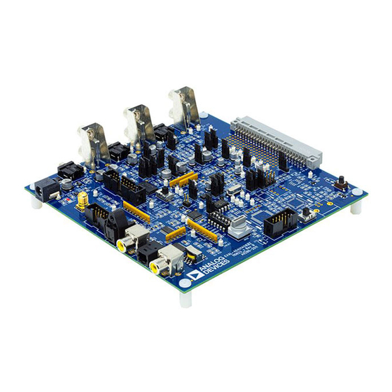
The EVAL-ADAU1401EBZ is a platform that operates all of the
ADAU1401's functions with a full range of analog and digital
inputs and outputs. Digital I/O connections are available in
both S/PDIF and 3-wire serial data formats. The DSP is
controlled by the SigmaStudio™ software, which interfaces to
the board through a USB connection. This evaluation board is
powered by a single supply, which is regulated to the proper
voltages on the board. The PCB is in a 6" × 6" 4-layer design,
with a single ground plane and a single power plane on the
inner layers.
The ADAU1401 can be controlled via the USBi interface control
2
board connected to the I
C/SPI communications interface.
On-board self-boot EEPROM is included for operating the
board independently of the SigmaStudio software. Push-
buttons, LEDs, potentiometers, and other interface options on
the included GPIO board can be connected to the evaluation
board to enable GPIO control.
The EVAL-ADAU1401EBZ can also be used for evaluation of
the pin-compatible
ADAU1701
The differences between the ADAU1401, ADAU1701, and
ADAU1702 are:
•
The ADAU1701 and ADAU1401 have 1024 program RAM
locations, while the ADAU1702 has 512 program RAM
locations.
•
The ADAU1701 has 2k words of data memory, while the
ADAU1702 has 0.5k words of data memory.
PLEASE SEE THE LAST PAGE FOR AN IMPORTANT
WARNING AND LEGAL TERMS AND CONDITIONS.
ADAU1401 SigmaDSP Evaluation Board
and
ADAU1702
SigmaDSP®s.
EVALUATION BOARD BLOCK DIAGRAM
ANALOG
INPUTS
CPLD
S/PDIF
RECEIVER AND
TRANSMITTER
POWER SUPPLY
REGULATION
Evaluation Board User Guide
•
The ADAU1401 is qualified over the automotive
temperature range (−40°C to +105°C), while the
ADAU1701 and ADAU1702 are qualified over the
consumer temperature range (0°C to 70°C).
PACKAGE CONTENTS
EVAL-ADAU1401EBZ evaluation board
GPIO control board
USBi board
Universal power supply
Mini-USB cable
Evaluation board/software quick-start guide, including a
download link for the SigmaStudio tools
OTHER SUPPORTING DOCUMENTATION
When using this evaluation board, refer also to the following
documentation available at www.analog.com:
•
ADAU1401, ADAU1701, ADAU1702 data sheets
•
AN-923 Application Note, Designing a System Using the
ADAU1701/ ADAU1702 in Self-Boot Mode
•
AN-951 Application Note, Using Hardware Controls with
SigmaDSP GPIO Pins
•
AN-1006 Application Note, Using the EVAL-ADUSB2EBZ
•
SigmaStudio help file (included with the software)
ANALOG
OUTPUTS
MULTI-
PURPOSE
PIN
INTERFACE
ADAU1401
USB
INTERFACE
Figure 1.
Rev. 0 | Page 1 of 20
UG-072
Advertisement
Table of Contents

Subscribe to Our Youtube Channel
Related Manuals for Analog Devices EVAL-ADAU1401EBZ


Summary of Contents for Analog Devices EVAL-ADAU1401EBZ
-
Page 1: General Description
The ADAU1401 is qualified over the automotive temperature range (−40°C to +105°C), while the The EVAL-ADAU1401EBZ is a platform that operates all of the ADAU1701 and ADAU1702 are qualified over the ADAU1401’s functions with a full range of analog and digital consumer temperature range (0°C to 70°C). -
Page 2: Table Of Contents
UG-072 Evaluation Board User Guide TABLE OF CONTENTS General Description ................. 1 Master Clock Settings ..............5 Package Contents ................1 Control Interface ................5 Other Supporting Documentation ..........1 Switch and Jumper Functions ............6 Evaluation Board Block Diagram ........... 1 Rotary Switch Settings ..............6 Revision History ................ -
Page 3: Quick Start Setup
Check the box for Include this location in the search. Power up the board. • The USBi driver is located in C:\Program Files\ Connect the audio cables. Analog Devices Inc\Sigma Studio\USB drivers, click Set the switches and jumpers. Next. SIGMASTUDIO SOFTWARE INSTALLATION •... -
Page 4: Your First Sigmastudio Project-Eq And Volume Control
UG-072 Evaluation Board User Guide Click the Schematic tab at the top of the screen. YOUR FIRST SIGMASTUDIO PROJECT—EQ AND In the Tree ToolBox section, expand the IO > Input. Click VOLUME CONTROL and drag an Input cell to the work area. The following is a procedure for building your first project in Similarly, expand Filters >... -
Page 5: Extended Setup
Evaluation Board User Guide UG-072 EXTENDED SETUP POWER SUPPLY MASTER CLOCK SETTINGS The evaluation board is powered by a single supply through The master clock connection of the ADAU1401 is set with Connector J14. The voltage on J14 should be 6 V dc to 9 V dc Jumper LK1 to Jumper LK4. -
Page 6: Switch And Jumper Functions
UG-072 Evaluation Board User Guide SWITCH AND JUMPER FUNCTIONS ROTARY SWITCH SETTINGS This evaluation board has many switches and jumpers; however, S2 is a hex rotary switch that controls the input and output for most applications, many of these need to be set only once signal routing on the evaluation board. -
Page 7: Ic Functions
Evaluation Board User Guide UG-072 IC FUNCTIONS RESET Table 4 explains the function of each IC on the evaluation The evaluation board can be reset with a push-button switch, board. The Lattice CPLD (U2) is only used for routing signals S1. -
Page 8: Typical Setups
UG-072 Evaluation Board User Guide TYPICAL SETUPS ALL SETUPS S/PDIF INPUT AND S/PDIF OUTPUT The switch and jumper settings in Table 5 are common for all Input comes from the stereo S/PDIF receiver to SDATA_IN0 typical setups described in this user guide. (Pin 10) of the ADAU1401 and outputs on whichever outputs (SDATA_OUTx) are designated in the SigmaStudio software. -
Page 9: Using The Gpio Board
Evaluation Board User Guide UG-072 USING THE GPIO BOARD The GPIO board is provided with the EVAL-ADAU1401EBZ to The 12 jumpers, J3 to J14, should be left on the pins to connect connect control and data interfaces to the multipurpose pins of the MPx pins to the control interfaces. -
Page 10: Evaluation Board Schematics
UG-072 Evaluation Board User Guide EVALUATION BOARD SCHEMATICS Figure 5. ADAU1401 Evaluation Board Schematic Rev. 0 | Page 10 of 20... - Page 11 Evaluation Board User Guide UG-072 Figure 6. CPLD Rev. 0 | Page 11 of 20...
- Page 12 UG-072 Evaluation Board User Guide Figure 7. Analog Input and Output Filters Rev. 0 | Page 12 of 20...
- Page 13 Evaluation Board User Guide UG-072 Figure 8. S/PDIF Receiver and Transmitter Rev. 0 | Page 13 of 20...
- Page 14 UG-072 Evaluation Board User Guide USBi Heade r Figure 9. Reset Generator and USBi Rev. 0 | Page 14 of 20...
- Page 15 Evaluation Board User Guide UG-072 Figure 10. Multipurpose Pin Interface Rev. 0 | Page 15 of 20...
- Page 16 UG-072 Evaluation Board User Guide Figure 11. Power Supply Rev. 0 | Page 16 of 20...
-
Page 17: Gpio Interface Board Schematics
Evaluation Board User Guide UG-072 GPIO INTERFACE BOARD SCHEMATICS Figure 12. GPIO Board Connector Rev. 0 | Page 17 of 20... - Page 18 UG-072 Evaluation Board User Guide Figure 13. GPIO Board Controls Rev. 0 | Page 18 of 20...
-
Page 19: Evaluation Board Pcb Silkscreen Drawing
Evaluation Board User Guide UG-072 EVALUATION BOARD PCB SILKSCREEN DRAWING Figure 14. Top Layer Silkscreen Rev. 0 | Page 19 of 20... - Page 20 By using the evaluation board discussed herein (together with any tools, components documentation or support materials, the “Evaluation Board”), you are agreeing to be bound by the terms and conditions set forth below (“Agreement”) unless you have purchased the Evaluation Board, in which case the Analog Devices Standard Terms and Conditions of Sale shall govern. Do not use the Evaluation Board until you have read and agreed to the Agreement.
Need help?
Do you have a question about the EVAL-ADAU1401EBZ and is the answer not in the manual?
Questions and answers