Table of Contents
Advertisement
Quick Links
One Technology Way • P.O. Box 9106 • Norwood, MA 02062-9106, U.S.A. • Tel: 781.329.4700 • Fax: 781.461.3113 • www.analog.com
FEATURES
For the evaluation of the
ADAU1977/ADAU1978/ADAU1979
quad ADCs
Total harmonic distortion (THD) plus noise (N): −95 dB at
−1 dBFS
Signal to noise ratio (SNR): 109 dB, A weighting filter
Built-in diagnostics for microphone inputs
APPLICATIONS
Automotive
PLEASE SEE THE LAST PAGE FOR AN IMPORTANT
WARNING AND LEGAL TERMS AND CONDITIONS.
Evaluating the
ADAU1977/ADAU1978/ADAU1979
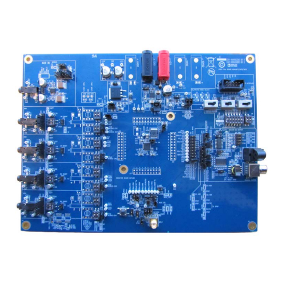
EVALUATION BOARD CONNECTION DIAGRAM
Evaluation Board User Guide
GENERAL DESCRIPTION
The
EVAL-ADAU1977Z/EVAL-ADAU1978Z/EVAL-
ADAU1979Z
is used for quick evaluation of the
ADAU1977/ADAU1978/ADAU1979
evaluation board can output up to four channels of digital
output. The evaluation board requires a power supply of +5 V
for the
ADAU1978
+5 V and ±20 V (optional) for testing the diagnostic features of
the ADAU1977.
Figure 1.
Rev. 0 | Page 1 of 27
quad ADCs. The
and the
ADAU1979
and a power supply of
UG-600
Advertisement
Table of Contents

Related Manuals for Analog Devices EVAL-ADAU1977


Summary of Contents for Analog Devices EVAL-ADAU1977
-
Page 1: Features
Evaluation Board User Guide UG-600 One Technology Way • P.O. Box 9106 • Norwood, MA 02062-9106, U.S.A. • Tel: 781.329.4700 • Fax: 781.461.3113 • www.analog.com Evaluating the ADAU1977/ADAU1978/ADAU1979 FEATURES GENERAL DESCRIPTION EVAL-ADAU1977Z/EVAL-ADAU1978Z/EVAL- For the evaluation of the ADAU1977/ADAU1978/ADAU1979 quad ADCs ADAU1979Z is used for quick evaluation of the ADAU1977/ADAU1978/ADAU1979... -
Page 2: Table Of Contents
UG-600 Evaluation Board User Guide TABLE OF CONTENTS Features ....................1 Evaluation Board Setup Instructions ..........6 Applications ..................1 Jumper Settings ................6 General Description ................. 1 USBi and Standalone GUI Setup ..........7 Evaluation Board Connection Diagram ........1 ADAU1977 Power-On ..............7 Revision History ................ -
Page 3: Evaluation Board Hardware
Evaluation Board User Guide UG-600 EVALUATION BOARD HARDWARE EVAL-ADAU1977Z board is common for the ADAU1977, OUTPUT CONNECTORS ADAU1978, and ADAU1979. The evaluation board is designed The ADC digital output is available at J25 (unbuffered) and J26 as a 4-layer printed circuit board (PCB). The top and bottom (buffered). - Page 4 UG-600 Evaluation Board User Guide Component No. Mnemonic Description MICBIAS-CH1 Selects the internal or external micbias for Channel 2. IOVDD Current Connector for measuring IOVDD current. 128fs Mode Selects the 96 k sample rate for the SPDIF transmitter. Coaxial Output Connector for SPDIF coaxial output.
-
Page 5: Setup Of The Evaluation Board Connections
Evaluation Board User Guide UG-600 SETUP OF THE EVALUATION BOARD CONNECTIONS CONTROL FOR AVDD SWITCHER NORMAL PWDN 1.2MHz CONNECT VOLTAGE SOURCE 600kHz TO INTRODUCE THE FAULT ON INPUT 0V TO 18V MAX DO NOT CONNECT POWER SUPPLY INTERNAL USE ONLY REQUIRED ONLY BUFFER TO BE USED FOR GENERATING FOR GENERATING... -
Page 6: Evaluation Board Setup Instructions
IOVDD position. Alternatively, if direct MCLK pin access connected at J8 to control the ADAU1977. is needed, set J43 to the 3V3 position. In this case, ensure The Analog Devices, Inc., USBi is the quickest way to set that the master clock supplied to the ADAU1977... -
Page 7: Usbi And Standalone Gui Setup
Evaluation Board User Guide UG-600 For the ADAU1977 line input application, take the following USBi AND STANDALONE GUI SETUP steps: To set up the USBi and standalone GUI, take the following steps: J9 is used to level shift the input source to the VBAT/2 If using the standalone GUI, click the appropriate x86 or level. -
Page 8: Microphone Diagnostics
UG-600 Evaluation Board User Guide Figure 3. Register Control for the ADAU1977 GUI Page 1 Figure 5. Register Control for the ADAU1977 GUI Page 3 MICROPHONE DIAGNOSTICS Microphone diagnostics are applicable for the ADAU1977 only, used with the microphone input application circuit, as described in the ADAU1977 data sheet. -
Page 9: Standalone Gui Spi Control
Evaluation Board User Guide UG-600 either using the microphone itself or by using the dummy Change Slide Switches S3, S4, and S5 to SPI mode. 300 Ω or 500 Ω resistor connected across the positive and Ensure JP6 is not installed. negative input terminals of the evaluation board. -
Page 10: Evaluation Board Schematics And Artwork
UG-600 Evaluation Board User Guide EVALUATION BOARD SCHEMATICS AND ARTWORK Figure 6. EVAL-ADAU1977Z Schematic, Page 1 of 6 Rev. 0 | Page 10 of 27... - Page 11 Evaluation Board User Guide UG-600 INPUT BUFFER FOR LEVEL SHIFTING INPUT CM INPUT SELECT HVDD 22pF 10.0kΩ 0.10µF HVDD 10.0kΩ ADJUST FOR DESIRED CM LEVEL +IN_BUFFER – VBAT [1,2,4] 10.0kΩ +OUT_BUFFER [2] V– HEADER_12WAY_UNSHROUD SLEEVE 10.0Ω U1-A [2] CM_IN+ HVSS 1/2VBAT 10µF CM_IN+ [2]...
- Page 12 UG-600 Evaluation Board User Guide I2S TO SPDIF SPDIF OPTICAL OUTPUT +3.3V +3.3V +3.3V IOVDD +3.3V C107 +3.3V 0.10µF SDIN FXLP34P5X ILRCLK DVDD ISCLK 47.5kΩ IOVDD 10.0kΩ [1] SDATAOUT1_X +3.3V OMCK 47.5kΩ AUDIO INPUT +3.3V 47.5kΩ TOTX147L(FT) 47.5kΩ APMS +3.3V EMPH [1] SDATAOUT2/TDM_SEL_X 47.5kΩ...
- Page 13 Evaluation Board User Guide UG-600 Figure 9. EVAL-ADAU1977Z Schematic, Page 4 of 6 Rev. 0 | Page 13 of 27...
- Page 14 UG-600 Evaluation Board User Guide IOVDD I2C LEVEL SHIFT & DUT ADDRESS I2C, SPI or STAND-ALONE MODE SELECT +3.3V IOVDD IOVDD 10.0kΩ 10.0kΩ ADDRESS 0.10µF 0.10µF TP11TP10 LEVEL SHIFT 2k00 2k00 VCCB VCCA 7 SCLB USBI_SCL[5,6] SCLA 3 SDAB SDAA USBI_SDA[5,6] I2C-SPI OR SA MODE SELECT I2C COMMUNICATION...
- Page 15 Evaluation Board User Guide UG-600 Figure 11. EVAL-ADAU1977Z Schematic, Page 6 of 6 Rev. 0 | Page 15 of 27...
-
Page 16: Board Layout
UG-600 Evaluation Board User Guide BOARD LAYOUT Figure 12. EVAL-ADAU1977Z/EVAL-ADAU1978Z/EVAL-ADAU1979Z Top Assembly Rev. 0 | Page 16 of 27... - Page 17 Evaluation Board User Guide UG-600 Figure 13. EVAL-ADAU1977Z Top Layer Rev. 0 | Page 17 of 27...
- Page 18 UG-600 Evaluation Board User Guide Figure 14. EVAL-ADAU1977Z Layer 2 Rev. 0 | Page 18 of 27...
- Page 19 Evaluation Board User Guide UG-600 Figure 15. EVAL-ADAU1977Z Layer 3 Rev. 0 | Page 19 of 27...
- Page 20 UG-600 Evaluation Board User Guide Figure 16. EVAL-ADAU1977Z Bottom Layer Rev. 0 | Page 20 of 27...
- Page 21 Evaluation Board User Guide UG-600 Figure 17. EVAL-ADAU1977Z/EVAL-ADAU1978Z/EVAL-ADAU1979Z Top Silkscreen Rev. 0 | Page 21 of 27...
- Page 22 UG-600 Evaluation Board User Guide Figure 18. EVAL-ADAU1977Z Fabrication Drawing Rev. 0 | Page 22 of 27...
-
Page 23: Ordering Information
Evaluation Board User Guide UG-600 ORDERING INFORMATION BILL OF MATERIALS Table 3. Component Number Description Manufacturer Part Number C10, C19 Ceramic capacitor, 10 µF, Digi-Key 445-1454-1-ND 50 V, X7R, 20%, 2220 C107, C108 Multilayer ceramic, 16 V, X7R Digi-Key PCC13490CT-ND (0402) C109 Multilayer ceramic capacitors... - Page 24 UG-600 Evaluation Board User Guide Component Number Description Manufacturer Part Number C6, C16, C87 Multilayer ceramic, 50 V, NP0 Digi-Key 490-1283-1-ND (0402) Multilayer ceramic, 25 V, X7R Digi-Key 490-4798-1-ND (1210), AECQ200 C70, C71 Multilayer ceramic, 10 V, X7R Digi-Key 490-3905-1-ND (0805) C8, C9 Multilayer ceramic, 10 V, X7R...
- Page 25 Evaluation Board User Guide UG-600 Component Number Description Manufacturer Part Number jumper, 0.10"; use shunt Tyco 881545-2 JP1 to J9, JP11 2-pin header, unshrouded Digi-Key S1011E-02-ND jumper, 0.10"; use shunt Tyco 881545-2 K1 to K12 Relay Telecom, single-pole Digi-Key. Z1230-ND single throw (SPST),1 A, 3 V dc SMA Chip ferrite bead, 100 Ω...
- Page 26 Digi-Key 5002K-ND outer diameter TP12 to TP14 Mini test point, white, 1" Digi-Key 5002K-ND outer diameter Dual bipolar/junction, field Analog Devices Inc. OP275GSZ effect transistor (JFET), audio operational amplifier. U10, U13 IC, buffer tristate, Digi-Key NC7SZ125P5XCT-ND noninverting, SC70-5 Quad buffer, tristate, 14-lead...
- Page 27 By using the evaluation board discussed herein (together with any tools, components documentation or support materials, the “Evaluation Board”), you are agreeing to be bound by the terms and conditions set forth below (“Agreement”) unless you have purchased the Evaluation Board, in which case the Analog Devices Standard Terms and Conditions of Sale shall govern. Do not use the Evaluation Board until you have read and agreed to the Agreement.
- Page 28 Authorized Distribution Brand: Website: Welcome to visit www.ameya360.com Contact Us: Address: 401 Building No.5, JiuGe Business Center, Lane 2301, Yishan Rd Minhang District, Shanghai , China Sales: Direct +86 (21) 6401-6692 Email amall@ameya360.com 800077892 Skype ameyasales1 ameyasales2 Customer Service: Email service@ameya360.com Partnership:...
Need help?
Do you have a question about the EVAL-ADAU1977 and is the answer not in the manual?
Questions and answers