Table of Contents
Advertisement
Quick Links
Advertisement
Table of Contents

Related Manuals for VAT 61228-KAGG-0002


Summary of Contents for VAT 61228-KAGG-0002
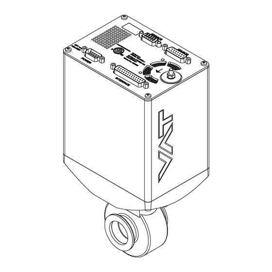
- Page 1 Installation, Operating & Maintenance Instructions Butterfly Pressure Control Valve with RS232 interface Series 612 DN 25 mm (I.D. 1") This manual is valid for the following product ordering numbers: 61228-KAGG-0002 Configured with firmware: 612P.1E.00 Sample picture 601894EA Edition 2013-04-12...
- Page 2 The VAT firmware may not be used for purposes other than those intended nor is it permitted to make copies of the VAT firmware. In particular, it is strictly forbidden to give copies of the VAT firmware to other people.
-
Page 3: Table Of Contents
Series 612 Contents Description of product ................ 5 Identification of product ....................5 Use of product ......................... 5 Used abbreviations ......................5 Related documents......................5 Important information....................... 5 Technical data ......................... 6 1.6.1 Control and actuating unit ................. 6 1.6.2 Valve unit ...................... - Page 4 Series 612 Operation ................... 51 Normal operation ......................51 5.1.1 Local operation ....................52 5.1.2 Remote operation .................... 53 Close valve ........................54 Open valve........................54 Position control ......................54 Pressure control ......................54 Display information ......................55 5.6.1 Power up ......................55 5.6.2 Operation ......................
-
Page 5: Description Of Product
Use of product This product is a Butterfly control valve for downstream pressure control in vacuum systems. Use product for clean and dry vacuum applications only. Other applications are only allowed with the written permission of VAT. Used abbreviations Abbreviation... -
Page 6: Technical Data
DESCRIPTION OF PRODUCT Series 612 Technical data 1.6.1 Control and actuating unit Describtion Input voltage +24 VDC (±10%) @ 0.5 V pk-pk [connector: POWER] max. Power consumption 38 W [connector: POWER] Sensor power supply output +24 VDC / 1500 mA max. [connector: SENSOR] Sensor input [connector: SENSOR]... -
Page 7: Valve Unit
Series 612 DESCRIPTION OF PRODUCT 1.6.2 Valve unit Data 1 × 10E-8 mbar to 1.2 bar (abs) Pressure range at 20 C 1 × 10E-9 mbar l/s Leak rate to outside at 20 C 2’000’000 (unheated and under clean conditions) Cycles until first service Admissible operating temperature +10°C to +150°C... -
Page 8: Safety
SAFETY Series 612 Safety Compulsory reading material Read this chapter prior to performing any work with or on the product. It contains important information that is significant for your own personal safety. This chapter must have been read and understood by all persons who perform any kind of work with or on the product during any stage of its serviceable life. -
Page 9: Personnel Qualifications
Series 612 SAFETY Personnel qualifications WARNING Unqualified personnel Inappropriate handling may cause serious injury or property damage. Only qualified personnel are allowed to carry out the described work. Safety labels Label Part No. Location on valve On protective foil covering of T-9001-156 valve opening 601894EA... -
Page 10: Design And Function
DESIGN AND FUNCTION Series 612 Design and Function Design Double seal of rotary feedthrough Integrated controller Double seal Coupling Plate Bearing Valve body Function The valve plate (5) acts as a throttling element and varies the conductance of the valve opening. The integrated controller (1) calculates the required plate position to achieve the setpoint pressure. -
Page 11: Pressure Control System Overview And Function
Series 612 DESIGN AND FUNCTION 3.2.1 Pressure control system overview and function Vacuum pressures are always absolute pressures unless explicitly specified as pressure differences. Valve Process chamber Gas inlet Pressure sensor(s) Sensor cable Controller and actuator Seff Cable to remote control unit Cable to power supply HV Pump Q / p... -
Page 12: Principle Of A Pressure Control System
DESIGN AND FUNCTION Series 612 3.2.1.1 Way of operation The controller compares the actual pressure in the process chamber given by the pressure sensor with the preset pressure. The controller uses the difference between actual and set pressure to calculate the correct position of the control valve. The controller drives the control valve into the correct position and the actual pressure again equals the set pressure. -
Page 13: Installation
Make sure that the supplied products are in accordance with your order. Inspect the quality of the supplied products visually. If it does not meet your requirements, please contact VAT immediately. Store the original packaging material. It may be useful if products must be returned to VAT. -
Page 14: Installation Into The System
INSTALLATION Series 612 Installation into the system WARNING Valve opening Risk of serious injury. Human body parts must be kept out of the valve opening and away from moving parts. Do not connect the controller to power before the valve is installed complete into the system. -
Page 15: Installation Space Condition
Series 612 INSTALLATION 4.2.1 Installation space condition Install the valve with integrated controller with space for dismantling and air circulation as shown in figure below. 70 mm 4.2.2 Connection overview System: Valve Process chamber Gas inlet Pressure sensor(s) Sensor cable(s) Controller and actuator Cable to remote control unit Cable to power supply... -
Page 16: Installation Procedure
Connect sensor cable [5] to sensor(s) and then to valve (connector: SENSOR). Refer to chapter «Electrical connection» for correct wiring. 61228-KAGG-0002 supports 1 sensor(s). Connect valve with cable [7] to remote control unit (connector: INTERFACE). Refer to chapter «RS232 connection» for correct wiring. -
Page 17: Tightening Torque
Refer also to chapter «Safety mode». This valve may optionally be equipped with a heating device. Connect VAT heating device according to manual of respective heating device. -
Page 18: Admissible Forces At Controller
INSTALLATION Series 612 4.4.1 Admissible forces at controller NOTICE Force at pedestal In case higher force is applied, the pedestal could be permanently damaged. – Do not pushing, shocking load, or stressing the valve controller – Do not deposit anything at valve controller The admissible force at valve controller in regards to the pedestal is shown in table below Overview... -
Page 19: Requirements To Sensor Connection
Series 612 INSTALLATION 4.4.2 Requirements to sensor connection To achieve fast and accurate pressure control a fast sensor response is required. Sensor response time: < 50ms. The sensor is normally connected to the chamber by a pipe. To maintain that the response time is not degraded by this connection it needs to meet the following requirements: Inner diameter of connection pipe: >... -
Page 20: Ground Connection
INSTALLATION Series 612 4.5.1 Ground connection Recommendation for ground strap between controller and system (chassis) Material L (Length max.) B1 (min.) B2 (min.) d1 ( ) d2 ( ) copper tinned 200 mm 25 mm 25 mm 4.5 mm customized Recommended torque: 1,3…1,7Nm System Ground strap... -
Page 21: Sensor Supply Concepts
Series 612 INSTALLATION 4.5.2 Sensor supply concepts This valve offers 3 alternative concepts to supply the sensor(s) with power. This depends on the sensor type and valve version that is used. This valve is available with an optional sensor power supply module (SPS) that converts 15 VDC from the 24 VDC. -
Page 22: Power And Sensor Connection (+24 Vdc Sensors)
INSTALLATION Series 612 4.5.3 Power and sensor connection (+24 VDC sensors) [612 . . - . . G . - ../ 612 . . - . . H . - ..versions recommended] 4.5.3.1 Sensor power wiring via controller Pins 4 and 8 must be... - Page 23 Series 612 INSTALLATION 4.5.3.2 Sensor power wiring external Pins 4 and 8 must be bridged for operation. An optional switch would allow for motor interlock to prevent valve from moving. Low range sensor may be connected to sensor 1 or sensor 2 input.
-
Page 24: Power And Sensor Connection ( 15 Vdc Sensors) Without Opt. Sps Module
INSTALLATION Series 612 4.5.4 Power and sensor connection ( 15 VDC sensors) without opt. SPS module [612 . . - . . G . - ../ 612 . . - . . H . - ..versions only] 4.5.4.1 Sensor power wiring via controller Pins 4 and 8 must be... - Page 25 Series 612 INSTALLATION 4.5.4.2 Sensor power wiring external Pins 4 and 8 must be bridged for operation. An optional switch would allow for motor interlock to prevent valve from moving. Low range sensor may be connected to sensor 1 or sensor 2 input.
-
Page 26: Service Port Connection
You can use our Software (freeware) 'Control Performance Analyzer' which can be downloaded from: http://www.vatvalve.com/customer-service/informations-and-downloads/control-performance-analyzer. Alternatively the VAT Service Box2 can be connected to the service port for setup and local operation. The service port is not galvanic isolated. Therefore we recommend using this only for setup, testing and maintenance and not for permanent control. -
Page 27: Rs232 Functions And Wiring
Series 612 INSTALLATION 4.5.6 RS232 Functions and Wiring This interface allows for remote operation by means of a command set based on the RS232 protocol. In addition there are 2 digital inputs and 2 digital outputs. Digital inputs may be operated either by switches or by voltage sources. - Page 28 INSTALLATION Series 612 b) Configuration with voltage source for digital inputs: Do not connect other pins than indicated in the schematics above! Use only screws with 4-40UNC thread for fastening the DB-25 connector! 28/83 Edition 2013-04-12 601894EA...
- Page 29 Series 612 INSTALLATION 4.5.6.1 Digital inputs Function Signal type Description Priority This function will close the valve. Valve will be in interlock mode as long as function is activated. After deactivation of function it will remain effective until - OPEN valve digital input is active - converse RS232 control command have been received Digital The function is activated when optocoupler is ‘on’...
-
Page 30: Initial Operation
INSTALLATION Series 612 Initial operation 4.6.1 Setup procedure RS232 To enable the valve for pressure control setup steps 1 to 6 must be performed. In case position control is required only it’s sufficient to perform steps 1 to 3. Setup step Description Turn on external + 24VDC power supply of valve (and external 15 Power up... -
Page 31: Valve Configuration
Series 612 INSTALLATION 4.6.3 Valve configuration Basic valve configuration must be adapted according to application needs. Definition of valve plate position in case of: After power up, default is ‘close‘. Power failure, default is ‘not defined‘. Only for versions that have Power Fail Option equipped [612 . . - . -
Page 32: Learn
INSTALLATION Series 612 Do not perform ZERO as long as pressure gauge voltage is shifting otherwise incorrect pressure reading is the result. Refer to manual of sensor manufacturer for warm up time. Do not perform ZERO, if the base pressure of your vacuum system is higher than 1‰... - Page 33 Series 612 INSTALLATION Gasflow calculation for LEARN: Do not apply a different gasflow for learn than determined below. Otherwise pressure control performance may be insufficient. Required pressure / flow regime must be known to calculate the most suitable learn gas flow for a specific application. 1.
-
Page 34: Tuning Of Control Performance
Go to ‘Tools / Create Diagnostic File’ in ‘Control View’ resp. ‘Control Performance Analyzer’ and save file Pressure / flow / gas conditions to be controlled Chamber volume Pumping speed (l/s) and pump type (e.g. turbo pump) System description Problem description Send diagnostic file with and all required information to tuning-support@vat.ch 34/83 Edition 2013-04-12 601894EA... - Page 35 Series 612 INSTALLATION 4.6.7.1 Gain factor adjustment The gain factor effects: Stability, Response time Default value is 1. Adjustment range is from 0.0001 to 7.5. Higher gain results in: faster response / higher over- / undershoot of pressure Lower gain results in: slower response/ lower over- / undershoot of pressure Adjustment procedure: 1.
- Page 36 INSTALLATION Series 612 4.6.7.2 Sensor delay adjustment Sensor delay adjustment effects: Stability Default value is 0. Adjustment range is from 0 to 1.0s. Pipes and orifices for sensor attachment delay response time and so badly impact pressure control stability. By adapting this parameter to the approximate delay time stability problems can be reduced. But control response time will be slowed down by this measure.
- Page 37 Series 612 INSTALLATION 4.6.7.3 Setpoint ramp adjustment Setpoint ramp effects: Undershoot of pressure, Response time Default value for Setpoint Ramp is 0. Adjustment range for Setpoint Ramp is from 0 to 10 s. This parameter defines the time that is used to decrease / raise pressure between 2 setpoints. Especially in pressure decrease situations at low flows pressure response can be improved much by adapting setpoint ramp time.
-
Page 38: Rs232 Interface Commands
INSTALLATION Series 612 4.6.7.4 Valve speed adjustment Valve speed effects: Response time Default value is 1000. Adjustment range is from 1 to 1000. This parameter effects valve plate actuating speed. Speed adjustment is effective for PRESSURE CONTROL and POSITION CONTROL. Normally best pressure control response is achieved with max. -
Page 39: Rs232 Control Commands
Series 612 INSTALLATION 4.7.2 RS232 Control commands Acknowledgement Command Control function (within 10ms after reception of command) Description [R:][xxxxxx][CR][LF] [R:][CR][LF] [i:38][CR][LF] [i:38][00xxxxxx][CR][LF] data length 6 characters for writing 8 characters starting with double zero for reading xxxxxx position SETPOINT, value depends on configuration, POSITION CONTROL refer to «RS232 with analog output setup commands, RANGE CONFIGURATION»... -
Page 40: Rs232 Inquiry Commands
INSTALLATION Series 612 4.7.3 RS232 Inquiry commands Acknowledgement Command (within 10ms after reception of command) Inquiry function Description [i:76][CR][LF] [i:76][xxxxxxsyyyyyyyabc][CR][LF] data length 17 characters xxxxxx position, return value depends on configuration, refer to «RS232 setup commands, RANGE CONFIGURATION» for details sign, 0 for positive pressure readings, - for negative pressure readings yyyyyyy pressure, return value depends on configuration,... - Page 41 Series 612 INSTALLATION Acknowledgement Command (within 10ms after reception of Inquiry function command) Description [i:64][CR][LF] [i:64][sxxxxxxx][CR][LF] data length 8 characters sign, 0 for positive readings, - for negative readings SENSOR 1 READING xxxxxxx sensor 1 reading, return value depends on configuration, refer to «RS232 setup commands, RANGE CONFIGURATION»...
- Page 42 INSTALLATION Series 612 Acknowledgement Command (within 10ms after reception of Inquiry function command) Description [i:51][CR][LF] [i:51][abcdefgh][CR][LF] data length 8 characters 0 = no service required 1 = service request, it is indicated when the control unit detects that motor steps are apparently not effective. This may happen when the valve is heavily contaminated or the gate seal is heavily sticking.
- Page 43 Series 612 INSTALLATION Acknowledgement Command (within 10ms after reception of command) Inquiry function Description [i:32][CR][LF] [i:32][abcdefgh][CR][LF] data length 8 characters 0 = LEARN not running, 1 = LEARN running 0 = LEARN data set present, 1 = LEARN data set not present 0 = ok 1 = last LEARN interrupted by user (control command) 2 = last LEARN interrupted by control unit...
- Page 44 This function returns firmware version of the device. [i:83][CR][LF] [i:83][xxxxxxxxxxxxxxxxxxxx][CR][LF] data length 20 characters xxx...xxx identification code, e.g. 61228-KAGG-0002/0001/, unused digits are filled up IDENTIFICATION with spaces (20 hexadecimal) This function returns controller's individual serial number. This code is unique for each valve and allows tracing.
-
Page 45: Rs232 Setup Commands
Series 612 INSTALLATION 4.7.4 RS232 Setup commands Acknowledgement Command (within 10ms after reception of command) Setup function Description [c:01][xx][CR][LF] [c:01][CR][LF] data length: 2 characters 00 = local operation (service port) 01 = remote operation, change to local enabled 02 = locked remote operation, change to local not possible via service port ACCESS MODE This function selects the access authorization to the valve. - Page 46 INSTALLATION Series 612 Acknowledgement Command (within 10ms after reception of command) Setup function Description [s:01][abcdefgh][CR][LF] [s:01][CR][LF] [i:01][CR][LF] [i:01][abcdefgh][CR][LF] data length 8 characters 0 = no sensor 1 = 1 sensor operation (sensor 1 input) 2 = 2 sensor operation with automatic changeover (low range = sensor 2 input, high range = sensor 1 input) 3 = 1 sensor operation (sensor 2 input) 4 = 2 sensor operation with automatic changeover...
- Page 47 Series 612 INSTALLATION Acknowledgement Command (within 10ms after reception of command) Setup function Description [s:21][abcdefgh][CR][LF] [s:21][CR][LF] [i:21][CR][LF] [i:21][abcdefgh][CR][LF] data length 8 characters range for POSITION: 0 = 0 – 1’000, 1 = 0 – 10’000, 2 = 0 – 100’000 bcdefgh upper value for PRESSURE and SENSOR READING: 1000 ...
- Page 48 INSTALLATION Series 612 Acknowledgement Command (within 10ms after reception of command) Setup function Description [Z:][CR][LF] [Z:][CR][LF] ZERO This command initiates ZERO to compensate for offset of gauge(s). Note: Refer to «ZERO» for correct zero procedure. [c:6002][xxxxxxxx][CR][LF] [c:60][CR][LF] data length: 8 characters xxxxxxxx System base pressure, value depends on configuration, refer to «RS232 setup commands, RANGE CONFIGURATION»...
- Page 49 Series 612 INSTALLATION Acknowledgement Command (within 10ms after reception of command) Setup function Description [s:02][abcdefgh][CR][LF] [s:02][CR][LF] [i:02][CR][LF] [i:02][abcdefgh][CR][LF] data length 8 characters 0 (reserved, do not change) gain factor: 0 = 0.10, 1 = 0.13, 2 = 0.18, 3 = 0.23, 4 = 0.32, 5 = 0.42, 6 = 0.56 7 = 0.75, 8 = 1.00, 9 = 1.33, A = 1.78, B = 2.37, C = 3.16, D = 4.22 E = 5.62, F = 7.50, G = 0.0001, H = 0.0003, I = 0.001, J = 0.003, K = 0.01, L = 0.02, M = 0.05...
-
Page 50: Error Messages
INSTALLATION Series 612 4.7.5 Error messages Description Error message Protocol Parity error [E:][000001][CR][LF] Framing error (data length, number of stop bits) [E:][000003][CR][LF] Input buffer overflow (to many characters) [E:][000002][CR][LF] Commands <CR> or <LF> missing [E:][000010][CR][LF] : missing [E:][000011][CR][LF] [E:][000020][CR][LF] Unknown command [E:][000021][CR][LF] [E:][000022][CR][LF] Invalid value... -
Page 51: Operation
Series 612 OPERATION Operation WARNING Unqualified personnel Inappropriate handling may cause serious injury or property damage. Only qualified personnel are allowed to carry out the described work. WARNING Valve opening Risk of serious injury. Human body parts must be kept out of the valve opening and away from moving parts. Do not connect the controller to power before the valve is installed complete into the system. -
Page 52: Local Operation
Local operation means that the valve is operated via the service port using a computer or the Service Box 2. When using a computer, a service cable and a software from VAT is required. You can use our Software (freeware) 'Control Performance Analyzer' which can be downloaded from: http://www.vatvalve.com/customer-service/informations-and-downloads/control-performance-analyzer. -
Page 53: Remote Operation
Series 612 OPERATION 5.1.2 Remote operation This product is equipped with a RS232 interface to allow for remote operation. See section «RS232 interface» for details. 'Control Performance Analyzer' software or 'Service Box 2' may be used for monitoring during remote control. 'Control Performance Analyzer' software 'Service Box 2' In case ‘Control Performance Analyzer’... -
Page 54: Close Valve
OPERATION Series 612 Close valve Local operation: Remote operation: (‘Control View’, ‘Control Performance Analyzer’ or (Refer to chapter: «Control commands» for ‘Service Box 2‘) details) Push CLOSE button Send CLOSE VALVE Open valve Local operation: Remote operation: (‘Control View’, ‘Control Performance Analyzer’ or (Refer to chapter: «Control commands»... -
Page 55: Display Information
Series 612 OPERATION Display information There is a 4 digit display located on 1 2 3 4 the panel. It displays configuration, status and position information. For details refer to following tables. Display 5.6.1 Power up Description Digit 1 Digit 2 Digit 3 Digit 4 At first all dots are illuminated... -
Page 56: Operation
OPERATION Series 612 5.6.2 Operation Description / Mode Digit 1 Digit 2 Digit 3 Digit 4 PRESSURE CONTROL mode POSITION CONTROL mode Valve closed Valve open Closed / open interlock (Valve closed / open 0…100 by digital input) = valve position (%, 0 = closed / 100 = open) HOLD (position frozen) activated ZERO running LEARN running... -
Page 57: Operation During Power Up
Series 612 OPERATION be repeated to attempt target position in the short term. But in the medium term the valve unit requires cleaning or inspection. ‘Service request’ (SR) would be indicated on the display or could be read via remote operation. Refer to «Display information» for details. Operation during power up Reaction of valve: Valve position... -
Page 58: Trouble Shooting
TROUBLE SHOOTING Series 612 Trouble shooting Failure Check Action No dots lighted on display 24 V power supply ok? Connect valve to power supply according to «Electrical connection» and make sure that power supply is working. Remote operation does not work - Local operation via service port active - Switch to remote operation. - Page 59 TROUBLE SHOOTING Series 612 Failure Check Action CLOSE VALVE does not work - Safety mode active, check for D on - Provide power to motor to allow for display? operation. - Refer to «Electrical connection» for details. - Refer to “Display shows «M C»” in this - Maintenance mode active table OPEN VALVE does not work...
- Page 60 TROUBLE SHOOTING Series 612 Failure Check Action PRESSURE CONTROL not optimal - Setup done completely? - Perform «Setup procedure» completely. - LEARN done? - Perform LEARN. Refer to «LEARN» for details. - ZERO performed before LEARN? - Perform ZERO then repeat LEARN. Refer to «Setup procedure»...
-
Page 61: Maintenance
Before carrying out any maintenance, please contact VAT. It has to be individually decided whether the maintenance can be performed by the customer or has to be carried out by VAT. Please write down the fabrication number of the valve before contact VAT. Refer to chapter «Identification of product»... -
Page 62: Maintenance Procedures
Replacement of Option board. Refer to chapter: «Replacement of Option board» Required frequency of cleaning and replacement of seals is depending on process conditions. VAT can give the following recommendations for preventive maintenance: Replacement of unheated heated 80 °C heated >... -
Page 63: Replacement Of Shaft Feedthrough Seals And Valve Cleaning
Series 612 MAINTENANCE 7.2.1 Replacement of shaft feedthrough seals and valve cleaning 7.2.1.1 Needed tools Allen Wrench 2mm feeler gauge Allen Wrench 3mm Note: Sample pictures Description Required tool Make sure that the valve is in closed position Vent vacuum system, disconnect electrical connections and remove valve from vacuum system. - Page 64 MAINTENANCE Series 612 Description Required tool Unfasten alternately the 2 mounting screws little by little. Allen Wrench If only one screw is fasten / unfasten, the mechanical unit will be damaged. Max. difference should be less than 1 turn or 0.5 turn of the screws.
- Page 65 Series 612 MAINTENANCE Description Required tool Lubricate seal contact surface of shaft with a slight film of vacuum grease (0.0125 ml). 12. Slide both o-rings onto shaft till the end. 13. Deposit 0.0375 ml vacuum grease between the o-rings Clean shaft from vacuum grease. Allen Wrench 15.
- Page 66 MAINTENANCE Series 612 Description Required tool 19. Assemble control and actuating unit to valve unit. Allen Wrench Tighten mounting screws adequately. Allen Wrench 20. Tighten clamp coupling with 1.1 Nm. 21. Reinstall valve into vacuum system according to chapter «Installation». 66/83 Edition 2013-04-12 601894EA...
-
Page 67: Replacement Of Option Board
Series 612 MAINTENANCE 7.2.2 Replacement of Option board NOTICE Electrostatic discharge Electronic components could be damage. All work on the control and actuating unit has to be done under ESD protected environment to prevent electronic components from damage. NOTICE Burned connector pins (spark) Connector pins or electronic parts could damage, if plugged and unplugged under power. - Page 68 MAINTENANCE Series 612 7.2.2.1 Durability of power fail battery The curves in the graph show the estimated life of Ultra Cap PFO in the worst condition (max. sensor load = 1 A, valve heating temperature = 150 °C). If the SPS is not fully loaded (< 1 A) or heating temperature of valve body is lower than 150 °C, the corresponding life time curve will be somewhere in between the upper and the lower curve.
- Page 69 Series 612 MAINTENANCE 7.2.2.2 Retrofit / replacement procedure Top view on control and actuating unit with panel removed: Master board Motor driver board Option board Interface board All boards have a fixed position into control and actuating unit. It is not possible to fit a board in other position as shown in picture above! Do not try out other positions, which maybe destroy the socket of boards! 601894EA...
- Page 70 MAINTENANCE Series 612 7.2.2.3 Needed tools Pozidriv screw driver size 1 Open end wrench 4.5mm Description Required tool Pozidriv screw driver Remove the panel screws. size 1 Remove female screw locks from POWER, SENSOR and INTERFACE Open end wrench 4.5 mm connectors.
- Page 71 Series 612 MAINTENANCE Description Required tool Remove the master board. Remove the interface board. Replace option board. Insert master board and interface board in reverse order as disassembled at correct positions (see steps 6 to 5). Insert option board at correct position (see step 7) 10.
-
Page 72: Repairs
Series 612 Repairs Repairs may only be carried out by the VAT service staff. In exceptional cases, the customer is allowed to carry out the repairs, but only with the prior consent of VAT. Please contact one of our service centers. You will find the addresses on our website www.vatvalve.com. -
Page 73: Dismounting And Storage
Series 612 DISMOUNTING AND STORAGE Dismounting and Storage WARNING Unqualified personnel Inappropriate handling may cause serious injury or property damage. Only qualified personnel are allowed to carry out the described work. Dismounting NOTICE Contamination Gate and other parts of the valve must be protected from contamination. Always wear clean room gloves when handling the valve. -
Page 74: Storage
DISMOUNTING AND STORAGE Series 612 Storage NOTICE Wrong storage Inappropriate temperatures and humidity may cause damage to the product. Valve must be stored at: – relative humidity between 10% and 70% – temperature between +10 °C and +50 °C – non-condensing environment NOTICE Inappropriate packaging Product may get damaged if inappropriate packaging material is used. -
Page 75: Packaging And Transport
If products are radioactively contaminated, the VAT form «Contamination and Radiation Report» must be filled out. Please contact VAT in advance. If products are sent to VAT in contaminated condition, VAT will carry out the decontaminating procedure at the customer's expense. -
Page 76: Transport
10.2 Transport NOTICE Inappropriate packaging Product may get damaged if inappropriate packaging material is used. Always use the original packaging material and handle product with care. VAT disclaims any liability for damages resulting from inappropriate packaging. 76/83 Edition 2013-04-12 601894EA... -
Page 77: Disposal
Series 612 DISPOSAL Disposal WARNING Unqualified personnel Inappropriate handling may cause serious injury or property damage. Only qualified personnel are allowed to carry out the described work. 601894EA Edition 2013-04-12 77/83... -
Page 78: Spare Parts
«Identification of product». This is to ensure that the appropriate spare parts are supplied. VAT makes a difference between spare parts that may be replaced by the customer and those that need to be replaced by the VAT service staff. -
Page 79: Drawing
Series 612 SPARE PARTS 12.1 Drawing Body with mechanism Shaft kit Valve body Plate kit Shaft feed through seals 601894EA Edition 2013-04-12 79/83... -
Page 80: Valve Unit
SPARE PARTS Series 612 All “Item“ refer to chapter «Drawing» 12.1.1 Valve unit Item Description Part number Body with mechanism 488956 Shaft kit 488946 Valve body 240574 Plate kit 253255 Plate screws 2 × 361960 12.1.2 Seals and grease Item Description Part number Shaft feed through seals kit... -
Page 81: Accessories
Series 612 SPARE PARTS 12.1.4 Accessories Description Part number 24 VDC power supply unit 249775 (input: 100 – 240 VAC) ‘Control Performance Analyzer’ free download from: ® http://www.vatvalve.com/customer-service/informations-and- package for Windows downloads/control-performance-analyzer ® ‘Control View’ software for Windows 248126 free download from: www.vatvalve.com Service cable 230327 (PC to valve Service connector) -
Page 82: Appendix
APPENDIX Series 612 Appendix No information entered on time. 82/83 Edition 2013-04-12 601894EA... - Page 83 Series 612 This page left blank intentionally. 601894EA Edition 2013-04-12 83/83...
Need help?
Do you have a question about the 61228-KAGG-0002 and is the answer not in the manual?
Questions and answers