VAT 615 Series Installation, Operating, & Maintenance Instructions
Butterfly control & isolation valve with extended control range with rs232 interface
Hide thumbs
Also See for 615 Series:
Table of Contents
Advertisement
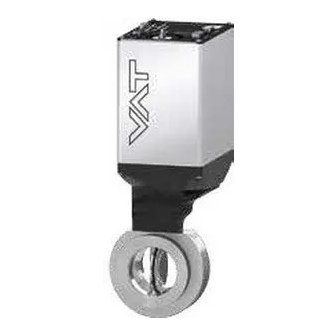
Butterfly control & isolation valve
with extended control range
with RS232 interface
This manual is valid for the valve ordering number(s):
615 . . - . . GG - . . . .
615 . . - . . GH - . . . .
615 . . - . . AG - . . . .
615 . . - . . AH - . . . .
615 . . - . . HG - . . . .
615 . . - . . HH - . . . .
615 . . - . . CG - . . . .
615 . . - . . CH - . . . .
615 . . - . . GV - . . . .
615 . . - . . GW - . . . .
615 . . - . . AV - . . . .
615 . . - . . AW - . . . .
615 . . - . . HV - . . . .
615 . . - . . HW - . . . .
615 . . - . . CV - . . . .
615 . . - . . CW - . . . .
SPS = Sensor Power Supply
configured with firmware
The fabrication number is indicated on each product as per the label
below (or similar):
ma de in Swit zerlan d
Fab rica tio n No .:
61 5 . . – . . . . – . . . . / . . . .
A – . . . . . .
Explanation of symbols:
Read declaration carefully before you start any other
action!
Attention!
Loaded springs and/or air cushions are potential
hazards!
Disconnect electrical power and compressed air
lines. Do not touch parts under voltage!
Read these «Installation, Operating & Maintenance Instructions» and the enclosed «General
Safety Instructions» carefully before you start any other action!
VAT Vakuumventile AG, CH-9469 Haag, Switzerland
Tel +41 81 771 61 61 Fax +41 81 771 48 30 CH@vatvalve.com www.vatvalve.com
Installation, Operating & Maintenance Instructions
Series 615 DN 63-100 (I.D. 2.5" - 4"), RS232
(1 sensor input)
(2 sensor inputs)
(1 sensor input / ±15V SPS)
(2 sensor inputs / ±15V SPS)
(1 sensor input / PFO)
(2 sensor inputs / PFO)
(1 sensor input / ±15V SPS / PFO)
(2 sensor inputs / ±15V SPS / PFO)
(1 sensor input / analog outputs)
(2 sensor inputs / analog outputs)
(1 sensor input / analog outputs / ±15V SPS)
(2 sensor inputs / analog outputs / ±15V SPS)
(1 sensor input / analog outputs / PFO)
(2 sensor inputs / analog outputs / PFO)
(1 sensor input / analog outputs / ±15V SPS / PFO)
(2 sensor inputs / analog outputs / ±15V SPS / PFO)
PFO = Power Failure Option
615P.1E.34
Fabrication num ber
sample picture
Keep body parts and objects away from the valve
opening!
Hot surfaces; do not touch!
Wear gloves!
290227EA
2011-06-24
1/79
Advertisement
Table of Contents

Related Manuals for VAT 615 Series


Summary of Contents for VAT 615 Series
- Page 1 Do not touch parts under voltage! Read these «Installation, Operating & Maintenance Instructions» and the enclosed «General Safety Instructions» carefully before you start any other action! VAT Vakuumventile AG, CH-9469 Haag, Switzerland 290227EA 1/79 Tel +41 81 771 61 61 Fax +41 81 771 48 30 CH@vatvalve.com www.vatvalve.com...
- Page 2 VAT products. The VAT firmware contains a limited, time unlimited user license. The VAT firmware may not be used for purposes other than those intended nor is it permitted to make copies of the VAT firmware. In particular, it is strictly forbidden to give copies of the VAT firmware to other people.
-
Page 3: Table Of Contents
5 Maintenance & repairs ............................56 Maintenance procedures ..........................57 Option board ..............................70 5.2.1 Durability of power fail battery ......................70 VAT Vakuumventile AG, CH-9469 Haag, Switzerland 290227EA 3/79 Tel +41 81 771 61 61 Fax +41 81 771 48 30 CH@vatvalve.com www.vatvalve.com 2011-06-24... - Page 4 Control and actuating unit..........................76 Accessories ..............................77 7.5.1 Centering ring with Viton o-ring ......................77 8 Warranty ................................. 78 VAT Vakuumventile AG, CH-9469 Haag, Switzerland 290227EA 4/79 Tel +41 81 771 61 61 Fax +41 81 771 48 30 CH@vatvalve.com www.vatvalve.com 2011-06-24...
-
Page 5: Use Of Product
This product is a Butterfly control valve with isolation functionality for downstream pressure control in vacuum systems. Use product for clean and dry indoor vacuum applications under the conditions indicated in chapter «Technical data» only! Other applications are only allowed with the written permission of VAT. Technical data... - Page 6 Refer to chapter «Sensor supply concepts» for details. Refer to chapter «Schematics» for details. PFO = Power Failure Option. Refer to «Behavior in case of power failure» for details. VAT Vakuumventile AG, CH-9469 Haag, Switzerland 290227EA 6/79 Tel +41 81 771 61 61 Fax +41 81 771 48 30 CH@vatvalve.com www.vatvalve.com...
- Page 7 - Shaft seal FKM (e.g. Viton®) - Plate seal FKM (e.g. Viton®) - Slide bearing for shaft iglidur® X VAT Vakuumventile AG, CH-9469 Haag, Switzerland 290227EA 7/79 Tel +41 81 771 61 61 Fax +41 81 771 48 30 CH@vatvalve.com www.vatvalve.com 2011-06-24...
- Page 8 (615 . . - . E. . - ..) Dimensions Refer to dimensional drawing of specific valve ordering number (available on request) VAT Vakuumventile AG, CH-9469 Haag, Switzerland 290227EA 8/79 Tel +41 81 771 61 61 Fax +41 81 771 48 30 CH@vatvalve.com www.vatvalve.com...
-
Page 9: Installation
Do not connect or disconnect sensor cable when device is under power. Connection overview Connectors at controller panel Ground connection VAT Vakuumventile AG, CH-9469 Haag, Switzerland 290227EA 9/79 Tel +41 81 771 61 61 Fax +41 81 771 48 30 CH@vatvalve.com www.vatvalve.com 2011-06-24... -
Page 10: Tightening Torque
Note: To provide power to the valve motor pins 4 and 8 must be bridged, otherwise motor interlock is active and the valve enters the safety mode and is not operative. Refer also to «Safety mode». This valve may optionally be equipped with a heating device. Connect VAT heating device according to manual of respective heating device. -
Page 11: Mounting With Centering Rings
Note: These torques are valid if depth of the mounting screws is min. 1 x thread diameter. Make sure that screws in use are capable to withstand applied torques. Lubricate screws slightly. VAT Vakuumventile AG, CH-9469 Haag, Switzerland 290227EA 11/79 Tel +41 81 771 61 61 Fax +41 81 771 48 30 CH@vatvalve.com www.vatvalve.com... -
Page 12: Admissible Forces
Axial tensile or Valve Bending moment «M» size compressive force «F » mm inch lbf. 2½ 26.5 1000 VAT Vakuumventile AG, CH-9469 Haag, Switzerland 290227EA 12/79 Tel +41 81 771 61 61 Fax +41 81 771 48 30 CH@vatvalve.com www.vatvalve.com 2011-06-24... -
Page 13: Admissible Forces At Controller
F = Force a = middle of aluminium part of controller (b / 2) pedestal 400 N pedestal VAT Vakuumventile AG, CH-9469 Haag, Switzerland 290227EA 13/79 Tel +41 81 771 61 61 Fax +41 81 771 48 30 CH@vatvalve.com www.vatvalve.com 2011-06-24... -
Page 14: Requirements To Sensor Connection
Dynamic stray magnetic fields may introduce noise to sensor output and should be avoided or shielded. VAT Vakuumventile AG, CH-9469 Haag, Switzerland 290227EA 14/79 Tel +41 81 771 61 61 Fax +41 81 771 48 30 CH@vatvalve.com www.vatvalve.com... -
Page 15: Electrical Connection
It is also possible to connect the ground strap at system chamber if it is well connected to PE. Note: Avoid low chassis cross section to the system PE connection. (Min. same cross section as ground strap) VAT Vakuumventile AG, CH-9469 Haag, Switzerland 290227EA 15/79 Tel +41 81 771 61 61 Fax +41 81 771 48 30 CH@vatvalve.com www.vatvalve.com... -
Page 16: Sensor Supply Concepts
615 . . - . . A . - ../ 615 . . - . . C . - ..SPS module included Note: The SPS module can be retrofitted. Refer to chapter «Retrofit / replacement procedure» for instruction. VAT Vakuumventile AG, CH-9469 Haag, Switzerland 290227EA 16/79 Tel +41 81 771 61 61 Fax +41 81 771 48 30 CH@vatvalve.com www.vatvalve.com... -
Page 17: Power And Sensor Connection (+24 Vdc Sensors)
Do not connect other pins that may damage sensors, power supply or controller! • Connector: Use only screws with 4-40UNC thread for fastening the connectors! VAT Vakuumventile AG, CH-9469 Haag, Switzerland 290227EA 17/79 Tel +41 81 771 61 61 Fax +41 81 771 48 30 CH@vatvalve.com www.vatvalve.com... - Page 18 • Connector: Use only screws with 4-40UNC thread for fastening the connectors! VAT Vakuumventile AG, CH-9469 Haag, Switzerland 290227EA 18/79 Tel +41 81 771 61 61 Fax +41 81 771 48 30 CH@vatvalve.com www.vatvalve.com...
-
Page 19: Power And Sensor Connection (±15 Vdc Sensors) Without Optional Sps Module
Do not connect other pins that may damage sensors, power supply or controller! • Connector: Use only screws with 4-40UNC thread for fastening the connectors! VAT Vakuumventile AG, CH-9469 Haag, Switzerland 290227EA 19/79 Tel +41 81 771 61 61 Fax +41 81 771 48 30 CH@vatvalve.com www.vatvalve.com... - Page 20 • Connector: Use only screws with 4-40UNC thread for fastening the connectors! VAT Vakuumventile AG, CH-9469 Haag, Switzerland 290227EA 20/79 Tel +41 81 771 61 61 Fax +41 81 771 48 30 CH@vatvalve.com www.vatvalve.com...
-
Page 21: Power And Sensor Connection (±15 Vdc Sensors) With Optional Sps Module
Do not connect other pins that may damage sensors, power supply or controller! • Connector: Use only screws with 4-40UNC thread for fastening the connectors! VAT Vakuumventile AG, CH-9469 Haag, Switzerland 290227EA 21/79 Tel +41 81 771 61 61 Fax +41 81 771 48 30 CH@vatvalve.com www.vatvalve.com... -
Page 22: Rs232 Interface Connection
The service port (connector: SERVICE) allows to connect the valve to a RS232 port of a computer. This requires a service cable and software from VAT. You can either use our freeware 'Control View', which can be downloaded from www.vatvalve.com or purchase our 'Control Performance Analyzer'. -
Page 23: Local Operation
Local operation means that the valve is operated via the service port using a computer or the Service Box 2. When using a computer, a service cable and a software from VAT are required. You can either download our freeware 'Control View' from or purchase our 'Control Performance Analyzer'. -
Page 24: Safety Mode
Valve position after power up is closed Valve position after power up is open Refer also to chapter «Display information». VAT Vakuumventile AG, CH-9469 Haag, Switzerland 290227EA 24/79 Tel +41 81 771 61 61 Fax +41 81 771 48 30 CH@vatvalve.com www.vatvalve.com... -
Page 25: Behavior In Case Of Power Failure
Default is not defined. Display indicates F. *) Provided that battery pack of the VAT controller is charged. Charging time after power up is 2 minutes max.. All parameters are stored in a power fail save memory. VAT Vakuumventile AG, CH-9469 Haag, Switzerland... -
Page 26: Display Information
1) SPS = optional ±15 VDC Sensor Power Supply module 2) PFO = Power Failure Option VAT Vakuumventile AG, CH-9469 Haag, Switzerland 290227EA 26/79 Tel +41 81 771 61 61 Fax +41 81 771 48 30 CH@vatvalve.com www.vatvalve.com... - Page 27 Digit 2 Digit 3 Digit 4 Fatal error occurred Error code. Refer to «Trouble shooting» for details VAT Vakuumventile AG, CH-9469 Haag, Switzerland 290227EA 27/79 Tel +41 81 771 61 61 Fax +41 81 771 48 30 CH@vatvalve.com www.vatvalve.com 2011-06-24...
-
Page 28: Setup Procedure
(Refer to chapter «Setup commands» for details) ‘Service Box 2‘) Send INTERFACE CONFIGURATION Do configuration in menu ‘Setup / Interface’. Send RANGE CONFIGURATION VAT Vakuumventile AG, CH-9469 Haag, Switzerland 290227EA 28/79 Tel +41 81 771 61 61 Fax +41 81 771 48 30 CH@vatvalve.com www.vatvalve.com 2011-06-24... -
Page 29: Valve And Sensor Configuration
Note: Do not perform ZERO, if the base pressure of your vacuum system is higher than 1‰ of sensor full scale. We recommend disabling ZERO function in this case; refer to «Valve and sensor configuration» of the setup procedure. Otherwise incorrect pressure reading is the result. VAT Vakuumventile AG, CH-9469 Haag, Switzerland 290227EA 29/79 Tel +41 81 771 61 61 Fax +41 81 771 48 30 CH@vatvalve.com www.vatvalve.com... -
Page 30: Learn
Note: Learn may take several minutes. Do not interrupt the routine as a single full run is required to ensure fast and accurate pressure control. The PID controller covers 5% to 5000% of the gas flow which was used for learn. VAT Vakuumventile AG, CH-9469 Haag, Switzerland 290227EA 30/79 Tel +41 81 771 61 61 Fax +41 81 771 48 30 CH@vatvalve.com www.vatvalve.com... - Page 31 [sccm] = 39.4 • p • C max. pressure to control [Torr] required lower conductance [l/s] VAT Vakuumventile AG, CH-9469 Haag, Switzerland 290227EA 31/79 Tel +41 81 771 61 61 Fax +41 81 771 48 30 CH@vatvalve.com www.vatvalve.com 2011-06-24...
-
Page 32: Close Valve
(Refer to chapter «RS232 control commands» for ‘Service Box 2‘) details) Select or enter pressure setpoint Send PRESSURE CONTROL VAT Vakuumventile AG, CH-9469 Haag, Switzerland 290227EA 32/79 Tel +41 81 771 61 61 Fax +41 81 771 48 30 CH@vatvalve.com www.vatvalve.com 2011-06-24... -
Page 33: Operation With 2 Sensors
For monitoring purpose each sensor signal may be read out individually. Note: Make sure that both sensors are calibrated. Note: Do not close optional gauge isolation valves during the transition phase between the sensors. VAT Vakuumventile AG, CH-9469 Haag, Switzerland 290227EA 33/79 Tel +41 81 771 61 61 Fax +41 81 771 48 30 CH@vatvalve.com www.vatvalve.com... -
Page 34: Tuning Of Control Performance
Pumping speed (l/s) and pump type (e.g. turbo pump) • System description • Problem description Send diagnostic file with and all required information to tuning-support@vat.ch VAT Vakuumventile AG, CH-9469 Haag, Switzerland 290227EA 34/79 Tel +41 81 771 61 61 Fax +41 81 771 48 30 CH@vatvalve.com www.vatvalve.com 2011-06-24... - Page 35 ‘Service Box 2‘) Go to ‘Setup / Control Parameter’ menu. Send Select sensor delay. PID CONTROLLER CONFIGURATION VAT Vakuumventile AG, CH-9469 Haag, Switzerland 290227EA 35/79 Tel +41 81 771 61 61 Fax +41 81 771 48 30 CH@vatvalve.com www.vatvalve.com 2011-06-24...
- Page 36 ‘Service Box 2‘) Go to ‘Setup / Control Parameter’ menu. Send Select setpoint ramp. PID CONTROLLER CONFIGURATION VAT Vakuumventile AG, CH-9469 Haag, Switzerland 290227EA 36/79 Tel +41 81 771 61 61 Fax +41 81 771 48 30 CH@vatvalve.com www.vatvalve.com 2011-06-24...
-
Page 37: Rs232 Interface
3.11.1 Settings The factory default setting of the RS232 interface might be changed to fit the application by using the Control View software, the Control Performance Analyzer software or the Service Box 2. VAT Vakuumventile AG, CH-9469 Haag, Switzerland 290227EA 37/79 Tel +41 81 771 61 61 Fax +41 81 771 48 30 CH@vatvalve.com www.vatvalve.com... -
Page 38: Schematics
Configuration with switches for digital inputs: Note: Do not connect other pins than indicated in the schematics above! Connector: Use only screws with 4-40UNC thread for fastening the DB-25 connector! VAT Vakuumventile AG, CH-9469 Haag, Switzerland 290227EA 38/79 Tel +41 81 771 61 61 Fax +41 81 771 48 30 CH@vatvalve.com www.vatvalve.com... - Page 39 Configuration with voltage source for digital inputs: Note: Do not connect other pins than indicated in the schematics above! Connector: Use only screws with 4-40UNC thread for fastening the DB-25 connector! VAT Vakuumventile AG, CH-9469 Haag, Switzerland 290227EA 39/79 Tel +41 81 771 61 61 Fax +41 81 771 48 30 CH@vatvalve.com www.vatvalve.com...
-
Page 40: Digital Inputs
Highest priority is 1. Functions with lower priorities will not be effective as long as higher priority functions are active. These digital inputs have higher priority than all RS232 commands. RS232 commands will not be accepted while digital inputs are active. VAT Vakuumventile AG, CH-9469 Haag, Switzerland 290227EA 40/79 Tel +41 81 771 61 61 Fax +41 81 771 48 30 CH@vatvalve.com www.vatvalve.com... -
Page 41: Rs232 Command Syntax
SETPOINT. Note: Reading returns pressure setpoint only in case pressure control is selected, otherwise position setpoint is returned. VAT Vakuumventile AG, CH-9469 Haag, Switzerland 290227EA 41/79 Tel +41 81 771 61 61 Fax +41 81 771 48 30 CH@vatvalve.com www.vatvalve.com... -
Page 42: Inquiry Commands
«RS232 setup commands, RANGE CONFIGURATION» for details This function returns the actual pressure. VAT Vakuumventile AG, CH-9469 Haag, Switzerland 290227EA 42/79 Tel +41 81 771 61 61 Fax +41 81 771 48 30 CH@vatvalve.com www.vatvalve.com... - Page 43 Note: In simulation mode the valve can demonstrate pressure control capability independent of other equipment such as vacuum chamber, flow controller and gauge. Normal operation is not possible when simulation is running. VAT Vakuumventile AG, CH-9469 Haag, Switzerland 290227EA 43/79 Tel +41 81 771 61 61 Fax +41 81 771 48 30 CH@vatvalve.com www.vatvalve.com...
- Page 44 2 (-1400000 ... 01400000 = -1.400000V ... +1.400000V) This function returns the sensor 2 offset voltage (adjusted by ZERO). VAT Vakuumventile AG, CH-9469 Haag, Switzerland 290227EA 44/79 Tel +41 81 771 61 61 Fax +41 81 771 48 30 CH@vatvalve.com www.vatvalve.com...
- Page 45 STATUS See in chapter «Trouble shooting» for details. This function returns an error code in case of any malfunction of the device. VAT Vakuumventile AG, CH-9469 Haag, Switzerland 290227EA 45/79 Tel +41 81 771 61 61 Fax +41 81 771 48 30 CH@vatvalve.com www.vatvalve.com...
- Page 46 (20 hexadecimal) This function returns an identification code. This code is unique for each valve and allows tracing. VAT Vakuumventile AG, CH-9469 Haag, Switzerland 290227EA 46/79 Tel +41 81 771 61 61 Fax +41 81 771 48 30 CH@vatvalve.com www.vatvalve.com...
-
Page 47: Setup Commands
0 (reserved, do not change) 0 (reserved, do not change) 0 (reserved, do not change) This function does the valve configuration. VAT Vakuumventile AG, CH-9469 Haag, Switzerland 290227EA 47/79 Tel +41 81 771 61 61 Fax +41 81 771 48 30 CH@vatvalve.com www.vatvalve.com... - Page 48 High range / Low range sensor full scale ratio * 1’000 (1000 … 100000). In case of a 1 sensor valve use any value within the valid range. This function does the sensor configuration for pressure control. VAT Vakuumventile AG, CH-9469 Haag, Switzerland 290227EA 48/79 Tel +41 81 771 61 61 Fax +41 81 771 48 30 CH@vatvalve.com www.vatvalve.com...
- Page 49 Above picture shows a 2 sensor system. In this configuration sensor 2 covers low range (100 mTorr) and sensor 1 covers high range (1 Torr). RANGE CONFIGURATION for PRESSURE resp. SENSOR READING is set to 10’000. Switchover between sensors is done automatically. VAT Vakuumventile AG, CH-9469 Haag, Switzerland 290227EA 49/79 Tel +41 81 771 61 61 Fax +41 81 771 48 30 CH@vatvalve.com www.vatvalve.com...
- Page 50 104 data sets. Each data set consists of 8 data bytes and needs to be uploaded separately. Note: Make sure that all 104 data sets will be uploaded. VAT Vakuumventile AG, CH-9469 Haag, Switzerland 290227EA 50/79 Tel +41 81 771 61 61 Fax +41 81 771 48 30 CH@vatvalve.com www.vatvalve.com...
- Page 51 00 = reset service request bit from WARNINGS RESET 01 = reset FATAL ERROR (restart control unit) This function resets warnings and errors. VAT Vakuumventile AG, CH-9469 Haag, Switzerland 290227EA 51/79 Tel +41 81 771 61 61 Fax +41 81 771 48 30 CH@vatvalve.com www.vatvalve.com...
-
Page 52: Error Messages
Command not accepted due to synchronization, CLOSED or OPEN by digital input, [E:][000082][CR][LF] safety mode or fatal error Hardware Command not applicable for hardware configuration [E:][000041][CR][LF] VAT Vakuumventile AG, CH-9469 Haag, Switzerland 290227EA 52/79 Tel +41 81 771 61 61 Fax +41 81 771 48 30 CH@vatvalve.com www.vatvalve.com 2011-06-24... -
Page 53: Trouble Shooting
- Provide power to motor to allow for operation. Motor Interlock is open - Refer to «Electrical connection» for details. VAT Vakuumventile AG, CH-9469 Haag, Switzerland 290227EA 53/79 Tel +41 81 771 61 61 Fax +41 81 771 48 30 CH@vatvalve.com www.vatvalve.com 2011-06-24... - Page 54 ZERO. - Enable ZERO. Refer to «Valve - ZERO disabled? configuration» for details. VAT Vakuumventile AG, CH-9469 Haag, Switzerland 290227EA 54/79 Tel +41 81 771 61 61 Fax +41 81 771 48 30 CH@vatvalve.com www.vatvalve.com 2011-06-24...
- Page 55 If you need any further information, please contact one of our service centers. You can find the addresses on our website: http://www.vat.ch VAT Vakuumventile AG, CH-9469 Haag, Switzerland 290227EA 55/79 Tel +41 81 771 61 61 Fax +41 81 771 48 30 CH@vatvalve.com www.vatvalve.com...
-
Page 56: Maintenance & Repairs
Contamination from the process may influence the function and requires more frequent maintenance. Before carrying out any maintenance or repairs, please contact VAT. It has to be individually decided whether the maintenance/repair can be performed by the customer or has to be carried out by VAT. The fabrication number on the valve made in Switzerland Fabrication No.:... -
Page 57: Maintenance Procedures
A critical factor influencing the maintenance period is the lifetime of the vacuum grease, being limited under increased temperature. In this case grease will separate to PTFE and oil. The oil may flow and contaminate the valve parts. VAT can give the following recommendations for preventive maintenance unheated and under clean condition: Seal Maintenance recommendation Plate Exchange after 100’000 isolation cycles or 2’000’000 control cycles... - Page 58 Remove plate from counter side Note: Take care to sealing surface inside the valve body! VAT Vakuumventile AG, CH-9469 Haag, Switzerland 290227EA 58/79 Tel +41 81 771 61 61 Fax +41 81 771 48 30 CH@vatvalve.com www.vatvalve.com 2011-06-24...
- Page 59 Note: For new o-ring refer to chapter spare parts. 10. Place the o-ring around the plate in the o-ring groove equally VAT Vakuumventile AG, CH-9469 Haag, Switzerland 290227EA 59/79 Tel +41 81 771 61 61 Fax +41 81 771 48 30 CH@vatvalve.com www.vatvalve.com 2011-06-24...
- Page 60 3.5 Nm (DN 80-100) 18. Reinstall valve into vacuum system according to chapter «Installation» of valve manual VAT Vakuumventile AG, CH-9469 Haag, Switzerland 290227EA 60/79 Tel +41 81 771 61 61 Fax +41 81 771 48 30 CH@vatvalve.com www.vatvalve.com 2011-06-24...
- Page 61 Note: If clamp coupling is separated, assemble them at control and actuating unit. VAT Vakuumventile AG, CH-9469 Haag, Switzerland 290227EA 61/79 Tel +41 81 771 61 61 Fax +41 81 771 48 30 CH@vatvalve.com www.vatvalve.com 2011-06-24...
- Page 62 O-ring Remove the o-ring with O- removal tool ring removal tool or compressed air Compressed VAT Vakuumventile AG, CH-9469 Haag, Switzerland 290227EA 62/79 Tel +41 81 771 61 61 Fax +41 81 771 48 30 CH@vatvalve.com www.vatvalve.com 2011-06-24...
- Page 63 12. Place the o-ring in the o-ring groove. Deposit the plate on a clean surface. 13. Unfasten complete 3 Allen Wrench screws. VAT Vakuumventile AG, CH-9469 Haag, Switzerland 290227EA 63/79 Tel +41 81 771 61 61 Fax +41 81 771 48 30 CH@vatvalve.com www.vatvalve.com 2011-06-24...
- Page 64 16. Remove both o-rings. removal tool Cleanroom 17. Clean shaft feedthrough and wipes soaked valve body. with isopropyl alcohol VAT Vakuumventile AG, CH-9469 Haag, Switzerland 290227EA 64/79 Tel +41 81 771 61 61 Fax +41 81 771 48 30 CH@vatvalve.com www.vatvalve.com 2011-06-24...
- Page 65 21. Deposit 0.05 ml vacuum grease between the o-rings. 22. Place the second o-ring at shaft feedthrough. VAT Vakuumventile AG, CH-9469 Haag, Switzerland 290227EA 65/79 Tel +41 81 771 61 61 Fax +41 81 771 48 30 CH@vatvalve.com www.vatvalve.com 2011-06-24...
- Page 66 25. Tighten the mounting Allen Wrench screws with 3.5 Nm. 26. Clean shaft from vacuum Cleanroom grease. wipes VAT Vakuumventile AG, CH-9469 Haag, Switzerland 290227EA 66/79 Tel +41 81 771 61 61 Fax +41 81 771 48 30 CH@vatvalve.com www.vatvalve.com 2011-06-24...
- Page 67 (C). Make sure that lever (B) is engaged at axis (C) completely. (mechanical close position). VAT Vakuumventile AG, CH-9469 Haag, Switzerland 290227EA 67/79 Tel +41 81 771 61 61 Fax +41 81 771 48 30 CH@vatvalve.com www.vatvalve.com 2011-06-24...
- Page 68 33. Assemble control and alcohol actuating unit to valve unit 34. Fasten 3 fastening screws Allen Wrench adequately VAT Vakuumventile AG, CH-9469 Haag, Switzerland 290227EA 68/79 Tel +41 81 771 61 61 Fax +41 81 771 48 30 CH@vatvalve.com www.vatvalve.com 2011-06-24...
- Page 69 35. Tighten clamp coupling with wrench 1.1 Nm 36. Reinstall valve into vacuum system according to chapter «Installation». VAT Vakuumventile AG, CH-9469 Haag, Switzerland 290227EA 69/79 Tel +41 81 771 61 61 Fax +41 81 771 48 30 CH@vatvalve.com www.vatvalve.com 2011-06-24...
-
Page 70: Option Board
Ambient temperature [°C] Note: This graph shows estimated life of UltraCap PFO for reference and not as guaranteed value. VAT Vakuumventile AG, CH-9469 Haag, Switzerland 290227EA 70/79 Tel +41 81 771 61 61 Fax +41 81 771 48 30 CH@vatvalve.com www.vatvalve.com... -
Page 71: Retrofit / Replacement Procedure
Note: All boards have a fixed position into control and actuating unit. It is not possible to fit a board in other position as shown in picture above. Do not try out other positions, that may be destroy the socket of boards! VAT Vakuumventile AG, CH-9469 Haag, Switzerland 290227EA 71/79 Tel +41 81 771 61 61 Fax +41 81 771 48 30 CH@vatvalve.com www.vatvalve.com... - Page 72 Open end wrench 4.5 mm SENSOR and INTERFACE connectors. Lift the panel carefully. Disconnect fan cable from board. VAT Vakuumventile AG, CH-9469 Haag, Switzerland 290227EA 72/79 Tel +41 81 771 61 61 Fax +41 81 771 48 30 CH@vatvalve.com www.vatvalve.com...
- Page 73 12. Tighten female screw locks from POWER, SENSOR and INTERFACE connectors with Open end wrench 4.5 mm 1.1 Nm (see step 1). VAT Vakuumventile AG, CH-9469 Haag, Switzerland 290227EA 73/79 Tel +41 81 771 61 61 Fax +41 81 771 48 30 CH@vatvalve.com www.vatvalve.com...
-
Page 74: Drawing
Installation, Operating & Maintenance Instructions Series 615 DN 63-100 (I.D. 2.5“ - 4”), RS232 Drawing VAT Vakuumventile AG, CH-9469 Haag, Switzerland 290227EA 74/79 Tel +41 81 771 61 61 Fax +41 81 771 48 30 CH@vatvalve.com www.vatvalve.com 2011-06-24... -
Page 75: Spare Parts
471253 471254 471255 Body compl. 407250 449825 367045 Plate 377974 377321 358337 Plate screw (3pcs) 355662 361781 VAT Vakuumventile AG, CH-9469 Haag, Switzerland 290227EA 75/79 Tel +41 81 771 61 61 Fax +41 81 771 48 30 CH@vatvalve.com www.vatvalve.com 2011-06-24... -
Page 76: Iso-F Valve Unit - Stainless Steel, Without Heating
(power failure option) Option board 376837 with SPS and PFO module *) Too many to list. Depends on configuration, please contact VAT. VAT Vakuumventile AG, CH-9469 Haag, Switzerland 290227EA 76/79 Tel +41 81 771 61 61 Fax +41 81 771 48 30 CH@vatvalve.com www.vatvalve.com... -
Page 77: Accessories
32036-QAZV 32038-QAZV 32040-QAZV with Viton o-ring (for ISO-KF and ISO-F installation Stainless steel 32036-QEZV 32038-QEZV 32040-QEZV only) VAT Vakuumventile AG, CH-9469 Haag, Switzerland 290227EA 77/79 Tel +41 81 771 61 61 Fax +41 81 771 48 30 CH@vatvalve.com www.vatvalve.com 2011-06-24... -
Page 78: Warranty
(including any delay in or failure to deliver), packaging, storage or use of any product sold or delivered by VAT shall fail to conform to the... - Page 79 Installation, Operating & Maintenance Instructions Series 615 DN 63-100 (I.D. 2.5“ - 4”), RS232 VAT Vakuumventile AG, CH-9469 Haag, Switzerland 290227EA 79/79 Tel +41 81 771 61 61 Fax +41 81 771 48 30 CH@vatvalve.com www.vatvalve.com 2011-06-24...
Need help?
Do you have a question about the 615 Series and is the answer not in the manual?
Questions and answers