VAT 613 Series Installation, Operating, & Maintenance Instructions
Butterfly pressure control valve with rs232 interface, dn 25-320 mm, i.d. 1" - 12", 2 sensor inputs / analog outputs / ±15v sps / pfo
Hide thumbs
Also See for 613 Series:
Table of Contents
Advertisement
Quick Links
Installation, Operating &
Maintenance Instructions
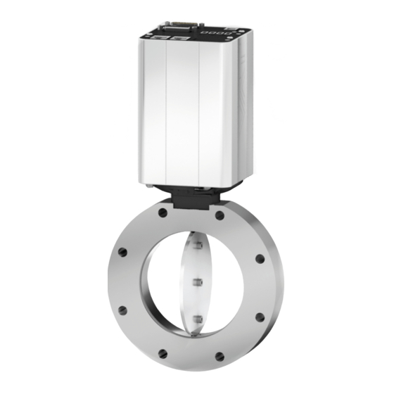
Butterfly Pressure Control Valve
with RS232 interface
Series 613
DN 25-320 mm (I.D. 1" - 12")
This manual is valid for the valve ordering number(s):
613 . . - . .GH - . . . .
613 . . - . .AH - . . . .
613 . . - . .HH - . . . .
613 . . - . .CH - . . . .
SPS = Sensor Power Supply
configured with firmware : F01.0C.28.xx
Sample picture
984360EC.DOCX
(2 sensor inputs / analog outputs)
(2 sensor inputs / analog outputs / ±15V SPS)
(2 sensor inputs / analog outputs / PFO)
(2 sensor inputs / analog outputs / ±15V SPS / PFO)
PFO = Power Failure Option
Edition 2022-08-12
Advertisement
Table of Contents
Troubleshooting

Related Manuals for VAT 613 Series


Summary of Contents for VAT 613 Series
- Page 1 Installation, Operating & Maintenance Instructions Butterfly Pressure Control Valve with RS232 interface Series 613 DN 25-320 mm (I.D. 1“ - 12") This manual is valid for the valve ordering number(s): 613 . . - . .GH - ..(2 sensor inputs / analog outputs) (2 sensor inputs / analog outputs / ±15V SPS) 613 .
- Page 2 The VAT firmware may not be used for purposes other than those intended nor is it permitted to make copies of the VAT firmware. In particular, it is strictly forbidden to give copies of the VAT firmware to other people.
-
Page 3: Table Of Contents
Series 613 Contents Description of product ................ 6 Identification of product ....................6 Firmware ......................... 6 Use of product ......................... 6 Used abbreviations ......................6 Related documents......................6 Important information....................... 6 Technical data ......................... 7 1.7.1 Control and actuating unit ................. 7 1.7.2 Valve unit ...................... - Page 4 Series 613 5.10.3 Warning/Error ....................36 5.10.4 Service ......................36 5.11 Valve Settings and States ....................37 5.11.1 States ......................37 5.11.2 Homing ......................37 5.11.3 Cycle Counter....................38 5.11.4 Position Restriction ..................38 5.11.5 Position Adaption .................... 39 5.12 Interface RS232/485 ......................
- Page 5 Series 613 Maintenance ..................126 Maintenance intervals....................126 Maintenance procedures ..................... 127 8.2.1 Replacement of shaft feedthrough seals and valve cleaning ......128 8.2.2 Replacement of Option board ............... 132 Repairs ..................... 137 FPR Service ........................ 137 Dismounting and Storage ............... 138 10.1 Dismounting ........................
-
Page 6: Description Of Product
Use of product This product is a Butterfly control valve for downstream pressure control in vacuum systems. Use product for clean and dry vacuum applications only. Other applications are only allowed with the written permission of VAT. Used abbreviations Abbreviation... -
Page 7: Technical Data
Series 613 DESCRIPTION OF PRODUCT Technical data 1.7.1 Control and actuating unit See product data sheet. 1.7.2 Valve unit See product data sheet. 984360EC.DOCX Edition 2022-08-12 7/149... -
Page 8: Safety
SAFETY Series 613 Safety Compulsory reading material Read this chapter prior to performing any work with or on the product. It contains important information that is significant for your own personal safety. This chapter must have been read and understood by all persons who perform any kind of work with or on the product during any stage of its serviceable life. -
Page 9: Personnel Qualifications
Series 613 SAFETY Personnel qualifications WARNING Unqualified personnel Inappropriate handling may cause serious injury or property damage. Only qualified personnel are allowed to carry out the described work. Safety labels Label Part No. Location on valve On protective foil covering of T-9001-156 valve opening 984360EC.DOCX... -
Page 10: Design And Function
DESIGN AND FUNCTION Series 613 Design and Function Design and Function Design Rotary feedthrough with double seal Integrated controller Double seal Coupling Plate Bearing Valve body Function The valve plate (5) acts as a throttling element and varies the conductance of the valve opening. The integrated controller (1) calculates the required plate position to achieve the setpoint pressure. -
Page 11: Pressure Control System Overview And Function
Series 613 DESIGN AND FUNCTION 4.2.1 Pressure control system overview and function Vacuum pressures are always absolute pressures unless explicitly specified as pressure differences. Valve Process chamber Gas inlet Pressure sensor(s) Sensor cable Controller and actuator Seff Cable to remote control unit Cable to power supply HV Pump Q / p... -
Page 12: Principle Of A Pressure Control System
DESIGN AND FUNCTION Series 613 4.2.1.1 Way of operation The controller compares the actual pressure in the process chamber given by the pressure sensor with the preset pressure. The controller uses the difference between actual and set pressure to calculate the correct position of the control valve. The controller drives the control valve into the correct position and the actual pressure again equals the set pressure. -
Page 13: Installation
Series 613 INSTALLATION Installation WARNING Unqualified personnel Inappropriate handling may cause serious injury or property damage. Only qualified personnel are allowed to carry out the described work. Initial procedure 984360EC Edition 12.08.2022 13/149... -
Page 14: Unpacking
Make sure that the supplied products are in accordance with your order. • Inspect the quality of the supplied products visually. If it does not meet your requirements, please contact VAT immediately. • Store the original packaging material. It may be useful if products must be returned to VAT. -
Page 15: Installation Into The System
Series 613 INSTALLATION Installation into the system WARNING Valve opening Risk of serious injury. Human body parts must be kept out of the valve opening and away from moving parts. Do not connect the controller to power before the valve is installed complete into the system. -
Page 16: Installation Hints
INSTALLATION Series 613 5.3.1 Installation Hints Install valve into the vacuum system. Valve seat side shall face process chamber. • Do not tighten the flange screws stronger than indicated under chapter «Tightening torque». • Do not admit higher forces to the valve than indicated under chapter «Admissible forces». -
Page 17: Admissible Forces
Series 613 INSTALLATION 5.3.3 Admissible forces NOTICE Force at valve body Forces from the weight of other components can lead to deformation of the valve body and to malfunction of the valve. Do not higher force the valve body as specified. The following forces are admissible. -
Page 18: Admissible Forces At Controller
INSTALLATION Series 613 5.3.4 Admissible forces at controller NOTICE Force at pedestal In case higher force is applied, the pedestal could be permanently damaged. – Do not pushing, shocking load, or stressing the valve controller – Do not deposit anything at valve controller The admissible force at valve controller in regards to the pedestal is shown in table below Overview... -
Page 19: Tightening Torque Dns 40 - 50Mm
Series 613 INSTALLATION 5.3.5 Tightening torque DNs 40 – 50mm Tightening torques for ISO-KF flange connections depend on the type of seal which is used. Follow recommendations of seal manufacturer. 5.3.5.1 ISO-KF Clamping connections Clamping chain (example) ISO-KF ISO-KF recommended recommended Valve size tightening torque... -
Page 20: Tightening Torque Dns 63 - 100Mm
INSTALLATION Series 613 5.3.6 Tightening torque DNs 63 – 100mm Tighten mounting screws of the flanges uniformly in crosswise order. Observe the maximum torque levels in the following table. Higher tightening torques deforms the valve body and may lead to malfunction of the valve. -
Page 21: Connection Overview
Series 613 INSTALLATION Connection overview Controller IC2-H3: Ground (FE) connection System: Valve Process chamber Gas inlet Pressure sensor(s) Sensor cable(s) Controller and actuator Cable to remote control unit Cable to power supply Pump 984360EC Edition 12.08.2022 21/149... -
Page 22: Power-, Ground- And Sensor Connection
5.5.1 Connection cable recommendations For Power Supply connection cables, VAT recommends: Class (min.) (Length max.) (diameter) AWG18 (shielded) 0.823 mm For Sensor & Signal connection cables, VAT recommends: Class (min.) (Length max.) (diameter) AWG22 (shielded) 20 m 0.326 mm 22/149 Edition 12.08.2022... -
Page 23: Ground Connection
Series 613 INSTALLATION 5.5.2 Ground connection Recommendation for ground connection between controller and system chassis with cable or with ground strap. Recommended torque: 1,3…1,7Nm Chassis (FE) (Functional Earth) Controller bottom side, (sample picture) • Recommendation for ground connection cable: AWG 12 (4 mm •... -
Page 24: Power And Sensor Supply Concepts
INSTALLATION Series 613 5.5.3 Power and Sensor supply concepts This valve offers 3 alternative concepts to supply the sensor(s) with power. This depends on the sensor type and valve version that is used. Concepts: 24 VDC sensors: • External +24 VDC supplied to POWER connector is feedthrough to SENSOR connector. Refer to chapter «Power and sensor connection (+24 VDC sensors) ». - Page 25 Low range sensor may be con- nected to sensor 1 or sensor 2 input. Do configuration accordingly • VAT fuse recommendation: (a) 3 AF • Use shielded sensor cable(s). Keep cable as short as possible, but locate it away from noise sources.
- Page 26 Low range sensor may be connected to sensor 1 or sensor 2 input. Do configuration accordingly. • VAT fuse recommendation: (a) 3 AF • Use shielded sensor cable(s). Keep cable as short as possible, but locate it away from noise sources. •...
- Page 27 Low range sensor may be connected to sensor 1 or sensor 2 input. Do configuration accordingly. • VAT fuse recommendation: (a) 3 AF • Use shielded sensor cable(s). Keep cable as short as possible, but locate it away from noise sources. •...
-
Page 28: Drive Power Enabled Switch, Safety Mode
INSTALLATION Series 613 5.5.4 Drive Power Enabled Switch, Safety Mode • By means of an external switch the motor power supply can be interrupted. • In this case the valve enters the ‘safety mode’. • This motor interlock prevents the valve from moving (e.g. maintenance work). •... -
Page 29: Power Up
Series 613 INSTALLATION Power Up After power up or possibly after a reset of the valve homing is necessary to determine the plate position. Refer to chapter Homing «5.11.2 » Power Down, Power Failure Option 5.7.1 Power down behavior in case of power failure Valve position before power failure: Reaction of valve: Closed (isolated) -
Page 30: Service Port, Cpa Software
INSTALLATION Series 613 Service Port, CPA software The ‘Service port is designed for ‘Local operation’ with the software CPA - Control Performance Analyzer. Note: Detailed help on the CPA is available in the help of the CPA itself. 5.8.1 How to start 1. -
Page 31: Update
This may result in an immediate movement of the valve depending on remote control. 5.8.2 Update It is easy to update to the latest version of the CPA which can be found on the VAT homepage: https://www.vatvalve.com/downloads/software 984360EC Edition 12.08.2022... -
Page 32: Display Information
INSTALLATION Series 613 Display Information There is a 4 digit display located on the controller. It displays configuration, status and position information. For details refer to following tables. 5.9.1 Power up Description Digit 1 Digit 2 Digit 3 Digit 4 ●... -
Page 33: Operation
Series 613 INSTALLATION 5.9.2 Operation Description / Mode Digit 1 Digit 2 Digit 3 Digit 4 INIT (start up) INIT (start up, leak tight) CLOSE OPEN C, 0…100 PRESSURE control valve position = closed, leak tight POSITION control = minimal conductance = maximum opened INTERLOCK Valve closed or open by digital input... -
Page 34: System Settings And States
5.10.1.2 Configuration Location: CPA/Parameters: System.Identifiaction.Configuration Parameter Description Valve Series 3-digit value representing the VAT valve series Valve Variant For some vale there exists different variants Nominal Diameter DN in mm. E.g DN250 Drive Parameter ID ID of the last drive file loaded on the valve. -
Page 35: Statistics
Series 613 INSTALLATION 5.10.1.4 Hardware Location: CPA/Parameters: System.Identification.Hardware Parameter Description Controller Type Identification of the use controller IC2H1, IC2H2, IC2H3 … Interface Type RS232/RS485 EtherCAT DeviceNet Logic Profibus CCLink EtherNet Option Type none Cluster SPS & PFO SPS & Cluster PFO &... -
Page 36: Warning/Error
INSTALLATION Series 613 5.10.3 Warning/Error Location: CPA/Parameters: System.Warning/Error Parameter Description Warning Bitmap Description No Learn Data Isolation valve does not work No Sensor Active PFO Not Ready Cluster Slave Offline Fieldbus Data Not Valid Compressed Air Not Falling when valve close Compressed Air Too Low 1024 Compressed Air Too High... -
Page 37: Valve Settings And States
Series 613 INSTALLATION 5.11 Valve Settings and States 5.11.1 States Location: CPA/Navigation/Parameters: Valve Parameter Description Actual Position Show position of the valve plate Position State Intermediate Closed Open Isolation State Not Isolated Isolated 5.11.2 Homing After power up or possibly after a reset of the valve homing is necessary to determine the plate position. Location: CPA/Navigation/Parameters: Valve.Homing Parameter Description... -
Page 38: Cycle Counter
INSTALLATION Series 613 5.11.3 Cycle Counter 5.11.3.1 Control Cycle A control cycle is a complete movement of the valve, from closing to opening and back to closing, or in percentage of movement it is 200%. Each movement is added up until 200% of the movement is reached, and then the cycle counter is incremented by 1. -
Page 39: Position Adaption
Series 613 INSTALLATION 5.11.5 Position Adaption 5.11.5.1 Usage Chamber Matching Adjustment of the conductance curve of different valves to obtain the same position at the same process points in different systems. Cluster Balance Adjusting the Position of individual valves in a valve cluster can be used to compensate certain Side- effects, e.g. -
Page 40: Interface Rs232/485
INSTALLATION Series 613 5.12 Interface RS232/485 This is an asynchronous serial communication method. The term serial means that the information is sent bit by bit. Asynchronous means that the information is not sent at previously agreed times. The sending of data can start at any arbitrary moment and it is part of the recipient's task to discover when a message starts and ends. -
Page 41: Rs485
Series 613 INSTALLATION 5.12.3 RS485 5.12.3.1 Connection Full Duplex Half Duplex 5.12.3.2 Configuration The factory default configuration of the RS232 interface are marked in bold and might be changed to fit the application by using the CPA software. Location: CPA\Parameters: Interface RS232/RS485.Settings Parameter Description Baud Rate... -
Page 42: Command Set
INSTALLATION Series 613 5.12.4 Command Set 5.12.4.1 General Commands and values are case sensitive. Acknowledgement within 10ms after reception of command. Wait for acknowledgement before sending a new command. Default command termination is CR and LF. This is adjustable. CR = Carriage Return (0D hexadecimal), LF = Linefeed (0A hexadecimal) Same Syntax for Commands over Service (CPA) as over RS232 interface. - Page 43 Series 613 INSTALLATION 5.12.4.3 Services Code Description SET a parameter to a value GET a value of a parameter 5.12.4.4 Parameter ID Each parameter is identified by an 8-digit hexadecimal value. Parameter ID via CPA: Left click on the displayed ID at the bottom of the parameter window: Export a parameter list to Excel: 984360EC Edition 12.08.2022...
- Page 44 INSTALLATION Series 613 5.12.4.5 Error Codes Code Error text Description no error no error wrong command length wrong command length value too low value out of range: lower then min limit value too high value out of range: higher then max limit resulting zero adjust offset value out of resulting zero adjust offset value out of range range...
- Page 45 5.12.4.6 Samples: command response Open: Control Mode to 4 p:010F0200000004 p:00010F0200000004 error 00 (successfully) service 01 (set) service 01 (set) parameter 0F020000 parameter 0F020000 Index Index value value Position Control: Control Mode to 2 p:010F0200000002 p:00010F0200000002 error 00 (successfully) service 01 (set) service 01 (set)
-
Page 46: Position And Pressure Units
5.12.5 Position and Pressure Units 5.12.5.1 Position Defined range is used in all commands with position values. Location: CPA/Navigation/Parameters: Interface.Scaling.Position Parameter Description Position Unit 1,10,90, 100,1000,10000, user specific Value Closest Position Range if the setting of Position Unit is user specific Value Open Position 5.12.5.2 Pressure... -
Page 47: Compound Commands
5.12.6 Compound Commands This function allows to SET and/or GET several values with one command. Compound is a table parameter that can hold up to 20 parameters. With the compound services 28, 29, 30 it is possible to set and/or get all the parameters contained in the compound parameter. - Page 48 Note: All not used indexes must be set to 0 View in the CPA Execute Compound 2 Service 29 Syntax p:|service|compound parameter ID|00 Send Receive p:|error|service|parameter|00|value;value;value;value… Execute Send p:29A10A020000 Receive p:0029A10A0200000;2;45.0;13.0;0: 48/149 Edition 12.08.2022 984360EC...
- Page 49 5.12.6.4 SET and GET Compound Build Compound 3 A10A0300 (with set and get values) Index Parameter ID [hex] Set compound members Control Mode 0F020000 p:01A10A0300000F020000 p:0BA10A030000 Target Position 11020000 p:01A10A03000111020000 p:0BA10A030001 Target Pressure 07020000 p:01A10A03000207020000 p:0BA10A030002 Separation p:01A10A0300030 p:0BA10A030003 Access Mode 0F0B0000 p:01A10A0300040F0B0000 p:0BA10A030004...
-
Page 50: Parameter Overview
5.12.7 Parameter Overview A parameter list is available in the CPA if there is a connection with the CPA. navigation → Parameters → Settings → Export Parameters to Excel Abbreviations Read Write Read Only None Volatile Volatile Access Data Type Info STRING Maximum length = 20 characters BOOL... - Page 51 Series 613 INSTALLATION 5.12.7.1 System Sub Group Parameter ID [hex] Data Type Acc Unit Max Description 0:Local Access Mode 0F0B0000 SINT8 1:Remote 2:Remote Locked 0:Init 7:Learn 1:Homing 8:Interlock Open 2:Position 9:Interlock Close 12:Power Control Mode 0F020000 SINT8 3:Close Failure 4:Open 13:Safety 5:Pressure Control 14:Error...
- Page 52 INSTALLATION Series 613 Actual Position 10010000 FLOAT [pos]* Position State 10100000 UINT8 0:Intermediate 1:Closed 2:Open Isolation State 10110000 BOOL 0:Not Isolated 1:Isolated Homing Start Condition 10200100 UINT8 0:Standard Do homing after restart if valve is not in sealed state, if it is sealed wait to a move command (except close command) 1:Open Command...
- Page 53 Series 613 INSTALLATION Compressed Air 10A40000 FLOAT mbar* Only for series 65.3 Pressure Compressed Air Error 10A90000 BOOL Only for series 65.3 Enable Speed Mode 10990000 0: Low Speed 1: Mid Speed 2: High Speed 3: Undefined 4: IC Slow Pos/Slow Prs 5: IC Fast Pos/Slow Prs 6: IC Fast Pos/Fast Prs Available speed Mode depends...
- Page 54 INSTALLATION Series 613 5.12.7.4 Pressure Control Sub Group Parameter ID [hex] Data Type Acc Unit Description Target Pressure 07030000 FLOAT mbar* This value is set as pressure controller input. It Used differs to the Target Pressure if a pressure ramp is used.
- Page 55 Series 613 INSTALLATION Sub Group Parameter ID [hex] Data Type Acc Unit Description General Profile Ramp Enable 07301801 BOOL Settings Threshold Mode 07301802 UINT8 0: Actual Pressure 1: Target Pressure Used Ramp Type 07301840 UINT8 0:Linear 1:Logarithmic 2:Exponential Actual Slope 07301841 FLOAT mbar*/...
- Page 56 INSTALLATION Series 613 5.12.7.5 Pressure Sensor Sub Group Parameter ID [hex] Data Type Acc Unit Max Description Actual Pressure 12100000 FLOAT mbar* Zero Adjust Sensor Selection 12040100 SINT8 0:Sensor 1 + 2 1:Sensor 1 2:Sensor 2 3: none Target Pressure 12040300 FLOAT mbar*...
- Page 57 Series 613 INSTALLATION 5.12.7.6 Interface RS232/RS485 Sub Group Parameter ID [hex] Data Type Acc Unit Max Description Operation Mode A1010000 SINT8 0:RS232 1:RS485 2:Service Interface Over RS232 Settings Baud Rate A1110100 SINT8 0:1200 3:9600 6:57600 1:2400 4:19200 7:115200 2:4800 5:38400 Data Bit Length A1110200 SINT8...
- Page 58 INSTALLATION Series 613 Sub Group Parameter ID [hex] Data Type Acc Unit Max Description Scaling Position Position Unit A1120101 SINT16 0:0 - 1 1:0 - 10 2:0 - 90 3:0 - 100 4:0 - 1000 5:0 - 10000 6:0 - 100000 7:User specific (Range is defined by Value Closest Position and Value Open Position) Value Closest Position...
- Page 59 Series 613 INSTALLATION 5.12.7.7 Power Connector IO Sub Group Parameter ID [hex] Data Type Acc Unit Description Digital Enable 37010100 BOOL Logic IO available on the valve power connector Input 1 State 37010200 BOOL Functionality 37010300 SINT8 0:Interlock Open 1:Interlock Close 2:Hold Inverted 37010400...
-
Page 60: Compatible Command Sets
Command Set Location: CPA\Parameters: Interface RS232/RS485.Command Set Parameter Description Command Set First VAT integrated controller with RS232 Service Port VAT PM controller PM V2 VAT PM controller with sensor crossover Tylan These instruction sets are often used in controllers from... - Page 61 Series 613 INSTALLATION System Data Description Resp Resp Set, Get Resp i:76 i:76 aaaaaa Compound bbbbbbbbcde a Pressure b Position c Access Mode: 0=Local, 1=Remote, 2=Locked d Control Mode: 0=Init,1=Homing,2=Position,3=Close,4=Open,5=Pressure Control,6=Hold,7=Learn,8=Interlock Open,9=Interlock Close,12=Power Failure,13=Safety,14=Error e Warning Present: (in i:51 or i:52) 0=no, 1=yes s:04 s:04 i:04...
- Page 62 INSTALLATION Series 613 Positon Data Set, Get Description Resp Resp Resp aaaaaa Actual Position Close Open i:38 i:38 aaaaaaaa Position Control, a Target Position Hold Position Mode (Release Hold) i:68 i:68 aaaaaa Speed: 0 - 1000 Pressure Reading Data Description Resp Resp Set, Get Resp...
- Page 63 Series 613 INSTALLATION Pressure Control Data Description Resp Resp Set, Get Resp i:38 i:38 aaaaaaaa Pressure Control, a Target Pressure Hold Pressure Control Mode (Release Hold) s:02 s:02 i:02 i:02 abcdeeff Pressure Control Setup s:02a i:02a a Controller: 0=Adaptive,1=PI Downstream,2=PI Upstream,3=Softpump b Gain Factor (Adaptive) 0=0.1,1=0.13,2=0.18,3=0.23,4=0.32,5=0.42,6=0.56,7=0.75,8=1.0,9=1.33,A=1.78,B=2.37, C=3.16,D=4.22,E=5.62,F=7.5,G=0.0001,H=0.0003,I=0.001,J=0.003,K=0.01,L=0.02,M=0.05...
- Page 64 INSTALLATION Series 613 Interface Data Description Resp Resp Set, Get Resp s:20 s:20 i:20 i:20 abcdefgh Setup1 a Baud Rate: 0=600,1=1200,2=2400,3=4800,4=9600,5=19200,6=38400,7=57600,8=115200,9=230400 b Parity Bit: 0=Even, 1=Odd, 2=Mark, 3=Space c Data Length: 0=7bit, 1=8bit d Stop Bit: 0=1bit, 1=2bit e Command Set: 0=IC, 1=PM f Digital Input 1: 0=Interlock Open, 1=Interlock Open Inverted, 2=Disabled...
- Page 65 Series 613 INSTALLATION Errors Description Error message Protocol Parity error E:000001 Input buffer overflow (to many characters) E:000002 Framing error (data length, number of stop bits) E:000003 Overrun (Service interface: Input buffer register overflow) E:000004 Commands CR or LF missing E:000010 : missing E:000011...
- Page 66 INSTALLATION Series 613 5.12.8.2 Command Set PM Note: All position and pressure values are integer values. Default Range pressure 0 … 1000, position 0 … 1000 (see Position and Pressure Units) Command Specific Settings Location: CPA\Parameters: Interface RS232/RS485.Settings Parameter Description R S Answer Specifies response to R (set position) and S (set pressure) commands Standard...
- Page 67 Series 613 INSTALLATION Position Control Data Description Resp Resp Set, Get Resp aaaaaa Actual Position Close Open aaaaaa Position Control, a Target Position Hold Position Mode (Release Hold) aaaaaa Speed: 0 - 1000 String Position Status: ____OK, POS-ER, AIR-ER i:04 i:04 V1:aV2:b Valve Status:...
- Page 68 INSTALLATION Series 613 i:02 i:02 abcdef Setup Sensor 1 and Sensor 2 i:03 i:03 a Voltage Range not used b Display Range not used c Display Unit not used d Gain Factor 0=0.1,1=0.13,2=0.18,3=0.23,4=0.32,5=0.42,6=0.56,7=0.75,8=1.0,9=1.33,A=1.78, B=2.37,C=3.16,D=4.22,E=5.62,F=7.5,G=0.0001,H=0.0003,I=0.001,J=0.003,K=0.01, L=0.02,M=0.05 e Sensor Type not used f Zero Adjust: 0=disabled, 1=enabled i:12...
- Page 69 Series 613 INSTALLATION Errors Description Error message Parity error E:000001 CR or LF missing E:000002 : missing E:000003 Wrong Letter Code E:000004 Numeric value not given in 6 digits E:000005 Numeric value out of range E:000006 Pressure Mode, Zero or Learn have been selected with no sensor connected E:000007 Instruction given in Access Mode Local E:000008...
- Page 70 INSTALLATION Series 613 5.12.8.3 Command Set PM V2 Note: This command set is quite the same as Command Set PM. Differences: Same commands as Command Set PM except Setup (s: instead of s:1 and s:2) Communication range for Pressure is settable (see s: command below) Additional commands: U:18, U:19;...
- Page 71 Series 613 INSTALLATION 5.12.8.4 Command Set Tylan Command Specific Settings Location: CPA\Parameters: Interface RS232/RS485.Settings Parameter Description Tylan M1 Use of M command (Control Gain) None Gain Factor/P-Gain Tylan X1 Use of X command (Control Lead) None Ramp Time/I-Gain Tylan J1 Use of J command (Valve Type) None Restart...
- Page 72 INSTALLATION Series 613 Response Description Config Low Threshold process limit #2 High Threshold process limit #2 Soft start Rate Setpoint n Setpoint Nr 1..5 m Request Nr 15 .. 19 Soft start Rate Setpoint Analog Soft start Rate Open Soft start Rate Close Position Indicator Range Output Direct Reverse Control Sensor Range...
- Page 73 Series 613 INSTALLATION 5.12.8.5 Command Set Tylan Type 2 This command set is the same as Tylan, except for the following settings and commands. Command Specific Settings Location: CPA\Parameters: Interface RS232/RS485.Settings Parameter Description Tylan V Use of V command (Controller Selector) None Pressure Control Selector Commands...
- Page 74 INSTALLATION Series 613 5.12.8.6 Command Set Tylan Type 1 Command Specific Settings Location: CPA\Parameters: Interface RS232/RS485.Settings Parameter Description Tylan V Use of V command (Controller Selector) None Pressure Control Selector Commands Note: Set commands have no response Response Description No Effect Open Close Hold...
-
Page 75: Digital Io On The Rs Interface Connector
Series 613 INSTALLATION 5.12.9 Digital IO on the RS interface connector There are 2 digital inputs, 2 digital outputs and 2 analog outputs. Digital inputs may be operated either by switches or by voltage sources. Digital inputs on the POWER and INTERFACE connector have the same priority. Active digital inputs have higher priority than RS232/RS485 commands. - Page 76 INSTALLATION Series 613 5.12.9.2 Schematic, Voltage source for digital inputs 5.12.9.3 Digital Input Pinout Default Function Interlock Close INPUT 1 INPUT 2 Interlock Open Switches COMMON COMMON Voltage Source Configuration Parameter Description Enable 1 Enables the input State 0 Not active 1 Active Functionality 0 Interlock Open...
- Page 77 Series 613 INSTALLATION 5.12.9.4 Digital Output Pinout Default Function Open OUTPUT 1 OUTPUT 2 Closed COMMON Configuration Parameter Description Enable 1 enables the output State 0 Not active 1 Active Functionality 0 OPEN valve is fully open 1 CLOSE valve is fully closed (isolated if valve has an isolation function) 2 HOLD valve is in hold state Inverted...
-
Page 78: Pressure Sensor
INSTALLATION Series 613 5.13 Pressure Sensor 5.13.1 Mechanical connection requirements Fast and accurate pressure control requires a fast sensor response. Sensor response time: < 50ms. The sensor is usually connected to the chamber by a pipe. The line must be short enough and the conductance must not be reduced by a too small line diameter or a low conductance shut-off valve, To maintain that the response time is not degraded by this connection it needs to meet the following requirements:... -
Page 79: Configuration
Series 613 INSTALLATION 5.13.2 Configuration The CPA window shows a good overview of the sensor settings: The valve supports 2 sensors. Zero Adjust is for offset compensation of linear sensors Crossover is automatic switch over between 2 linear sensors 984360EC Edition 12.08.2022 79/149... - Page 80 INSTALLATION Series 613 Location: CPA/Navigation/Parameters: Pressure Sensor.Sensor 1, Pressure Sensor.Sensor 2 Parameter Description Available Set to ‘True’ if a sensor is connected Enable Set to ‘True’ if the sensor signal is used for pressure control Input Source ‘Analog’ Sensor has an analog voltage interface and is direct connected to the valve.
-
Page 81: Crossover (2 Sensor Operation Mode)
Series 613 INSTALLATION 5.13.3 Crossover (2 sensor operation mode) If two sensors are connected to the controller uses both for pressure control and pressure feedback. The controller selects each sensor or blends both sensor signals to the “Actual Pressure” used for control and feedback. -
Page 82: Zero Adjust
INSTALLATION Series 613 5.13.4 Zero Adjust Zero Adjust allows for the compensation of the sensor offset voltage. Note: A maximum offset voltage of +/- 1.4 V can be compensated. Location: CPA/Navigation/Parameters: Pressure Sensor.Zero Adjust Parameter Description Zero Adjust.Sensor Selection Select the sensor for the zero adjust: •... -
Page 83: Logarithmic Pressure
Series 613 INSTALLATION 5.13.5 Logarithmic Pressure To control wide pressure ranges, it is advantageous to control with a logarithmic signal. Note: Only the PI and the Softpump controller can control with a logarithmic signal. Adaptive controller needs a linear signal. Location: CPA/Parameters: Pressure Sensor.General Settings.Logarithmic Pressure Parameter Description... -
Page 84: Power Connector Digital Io
INSTALLATION Series 613 5.14 Power Connector Digital IO Do not connect other pins than indicated in the schematics! Use only screws with 4-40UNC thread for fastening the DA-15 connector! 5.14.1 Digital Input 5.14.1.1 Connection Default Function Interlock Open INPUT 1 INPUT 2 Interlock Close COMMON... -
Page 85: Digital Output
Series 613 INSTALLATION 5.14.2 Digital Output 5.14.2.1 Connection Default Function Open OUTPUT 1 OUTPUT 2 Closed COMMON 5.14.2.2 Parameter, Configuration Location: CPA/Navigation/Parameters: Power Connector IO.Digital Output Parameter Description Enable 1 enables the output State 0 Not active 1 Active Functionality 0 OPEN valve is fully open 1 CLOSE... -
Page 86: Operation
OPERATION Series 613 Operation WARNING Unqualified personnel Inappropriate handling may cause serious injury or property damage. Only qualified personnel are allowed to carry out the described work. WARNING Valve opening Risk of serious injury. Human body parts must be kept out of the valve opening and away from moving parts. Do not connect the controller to power before the valve is installed complete into the system. -
Page 87: Access Mode
Series 613 OPERATION Access Mode 6.1.1 Overview Defines whether the interface or the CPA via the service port has the rights to control the valve Location: CPA/Parameters System Access Mode Control Permission Comment Local Remote INTERFACE Master CPA can switch to Local Locked INTERFACE Master CPA can’t switch to Local... -
Page 88: Control Mode
OPERATION Series 613 Control Mode The Control Mode represents the state machine of the valve. Writing to Control Mode requests a change in the state while reading Control Mode returns the actual state of the state machine. Init State after power up. Remains if Homing is not started or no Exception occurs Homing The valve performs the homing procedure to initialize the position. -
Page 89: View
Series 613 OPERATION CPA/Parameter: System.Control Mode Location: 6.2.1 View First digit on display Init Homing Close Open Pressure Control Position Interlock Open or Close Hold Learn Safety Mode Power Failure Error 984360EC Edition 12.08.2022 89/149... -
Page 90: Pressure Control
OPERATION Series 613 Pressure Control 6.3.1 Controller units The valve has four identical pressure controller units. Controller Selector defines which unit is used for the pressure control. Controller Selector Controller 1 Controller 2 Controller 3 Controller 4 Most applications do not need more than one controller unit. But if the result of the pressure control does not meet the expectations, different controller units can be an option for optimization: With the four controller units it is possible to use a certain controller unit for a specific pressure set point. -
Page 91: Control Algorithm
Series 613 OPERATION 6.3.2 Control algorithm 6.3.2.1 Overview Adaptive This is the most dynamic control algorithm. Before using adaptive control algorithm, a special procedure called “learn” must be executed first (see chapter below). The valve will observe the behavior of the vacuum system by moving the valve to different positions. During the learn procedure the valve performs an internal parameter estimation correspondent to the vacuum system. - Page 92 OPERATION Series 613 6.3.2.2 Choose correct control algorithm Constant gas flow available Constant gas flow System Configuration not available Tv*<= 500 sec Tv* > 500 sec Downstream Process chamber Adaptive Control valve Pump Upstream Control valve Process chamber Pump Soft Pump Soft Pump * Use the formula below to define the applicable pressure control algorithm.
-
Page 93: Adaptive Algorithm
Series 613 OPERATION 6.3.3 Adaptive algorithm This control algorithm may be used for downstream pressure control. Before using adaptive control algorithm, a special procedure called “learn” must be executed first (see chapter below). 6.3.3.1 Control Parameter Location: CPA/Navigation/Parameters: Pressure Control.Controller x.Control Settings Parameter Description Gain Factor... - Page 94 OPERATION Series 613 6.3.3.2 Learn LEARN adapts the PID controller of the valve to the vacuum system and its operating conditions. LEARN must be executed only once during system setup. The LEARN routine determines the characteristic of the vacuum system. Based on this, the PID controller is able to run fast and accurate pressure control cycles.
- Page 95 Series 613 OPERATION Parameters Executing Location: CPA/Navigation/Parameters: Pressure Control.Adaptive Learn Parameter Description Start Learn Starts the learn Type Standard A positioning sequence is executed and various measured values are recorded in the process. Short Opens the valve and measures the pumping speed. Information about flow and volume is required.
- Page 96 OPERATION Series 613 Parameters Learn Bank Location: CPA/Navigation/Parameters: Pressure Control.Adaptive Learn.Learn Bank x Parameter Description Status Not Used Empty learn bank Available Data available. Evaluation possible with the pressure position curve in the CPA/Navigation/Adaptive Learn Data Available with The data may still be suitable for pressure control. warnings Evaluation possible with the pressure position curve in the CPA/Navigation/Adaptive Learn Datas...
- Page 97 Series 613 OPERATION Execute a learn procedure Set specific gas flow according to calculation below or the calculation in the CPA ‘Adaptive Learn’ window: Learn does not need to be performed with the process gas. Instead N or Ar may be used. Set parameter Bank Selection, if only one learn is used take Bank 1.
- Page 98 OPERATION Series 613 Gasflow calculation for Learn Do not apply a different gasflow for learn than determined below. Otherwise pressure control performance may be insufficient. Required pressure / flow regime must be known to calculate the most suitable learn gas flow for a specific application.
- Page 99 Series 613 OPERATION Evaluation and exchange of learn data Location: CPA/Navigation/Adaptive Learn Data The window shows the pressure position curve of the stored data in the learning banks With the menu buttons it is possible to exchange data between learn banks and between valves. 984360EC Edition 12.08.2022 99/149...
- Page 100 OPERATION Series 613 6.3.3.3 Tuning Normally the default settings will result in good pressure control performance. For some applications tuning may be required to improve performance. The tuning procedures for each parameter (grey boxes) and its default values are described separately below. Strictly keep the procedure order. 100/149 Edition 12.08.2022 984360EC...
- Page 101 Series 613 OPERATION Gain Factor adjustment The Gain Factor effects: Stability, Response time Adjustment range is from 0.0001 to 100.0 - Higher gain results in: faster response, higher over- undershoot of pressure - Lower gain results in: slower response, lower over- undershoot of pressure Adjustment procedure: 1.
- Page 102 OPERATION Series 613 Setpoint Ramp adjustment Setpoint Ramp effects: Undershoot of pressure, Response time Note: The ramp is described in detail in capital Pressure Ramp. This parameter defines the time that is used to decrease / raise pressure between 2 setpoints. Especially in pressure decrease situations at low flows pressure response can be improved much by adapting setpoint ramp time.
- Page 103 Pressure / flow / gas conditions to be controlled • Chamber volume • Pumping speed (l/s) and pump type (e.g. turbo pump) • System description • Problem description Send diagnostic file with and all required information to tuning-support@vat.ch 984360EC Edition 12.08.2022 103/149...
-
Page 104: Pi Algorithm
OPERATION Series 613 6.3.4 PI algorithm This control algorithm may be used for downstream or upstream pressure control depending on configuration. 6.3.4.1 Control Parameter Location: CPA/Navigation/Parameters: Pressure Control.Controller x,Control Settings Parameter Description P-Gain The P-Gain is the proportional factor of the fixed control algorithm. A higher P-Gain results in faster response, higher over- / undershoot of pressure. - Page 105 Series 613 OPERATION 6.3.4.2 Tuning The PI parameters of the pressure controller require correct adjustment. These parameters must be set once during system setup and are stored in the device memory which is power fail save. Based on the PI controller configuration, the valve is able to run fast and accurate pressure control cycles. The PI parameters can be evaluated using below instruction.
- Page 106 OPERATION Series 613 Optimizing P-Gain While optimizing P-Gain, the gas flow determined above has to be constant all the time. Start optimization with P-Gain set to 1.0 and I-Gain set to 0.0. Set chamber pressure to SP2, wait until the pressure is stable. Set pressure to SP1. If the transition from SP2 to SP1 results in a significant pressure over shoot or even does not stabilize at all, the P- Gain is too high.
- Page 107 Pressure / flow / gas conditions to be controlled • Chamber volume • Pumping speed (l/s) and pump type (e.g. turbo pump) • System description • Problem description Send diagnostic file with and all required information to tuning-support@vat.ch 984360EC Edition 12.08.2022 107/149...
- Page 108 OPERATION Series 613 6.3.4.3 Soft Pump/Vent algorithm This control algorithm may be used to control pressure ramps during pump down or venting the chamber. This is a modified PI controller that has been optimized to start up very gently when the valve is opened.
- Page 109 Pressure / flow / gas conditions to be controlled • Chamber volume • Pumping speed (l/s) and pump type (e.g. turbo pump) • System description • Problem description Send diagnostic file with and all required information to tuning-support@vat.ch 984360EC Edition 12.08.2022 109/149...
-
Page 110: Pressure Ramp
OPERATION Series 613 6.3.5 Pressure Ramp Basically, the pressure ramp is used to limit the rate of pressure change. Actual Pressure Pressure Controller Target Pressure Target Pressure Used Pressure Used Ramp 6.3.5.1 Configuration Location: CPA/Navigation/Parameters: Pressure Control.Controller x.Ramp Parameter Description Enable Activate / Deactivate pressure target ramp Mode... - Page 111 Series 613 OPERATION 6.3.5.2 Mode Time Slope Unit: seconds Unit: Pressure / seconds Time is constant, slope varies Slope is constant, time varies Example: 2 sec Example: 10mTorr/second 6.3.5.3 Type Linear Logarithmic Exponential 984360EC Edition 12.08.2022 111/149...
- Page 112 OPERATION Series 613 6.3.5.4 Applications Examples Soft pump Ramp Mode = Time Ramp Time = 100 sec Ramp Type = Linear Target Pressure = 0 Minimize pressure over- or undershoots New Target Pressure without pressure ramp New Target Pressure with pressure ramp Smoothing a staircase Pressure ramp with new target pressure to the valve every second is smoothed by a 1 sec internal ramp Ramp Time = 1sec...
-
Page 113: Profile Ramp
Series 613 OPERATION 6.3.6 Profile Ramp Profile Ramp is a Target Pressure ramp that depends on pressure ranges (segments). It is mainly used to create soft pumping or soft venting profiles. To design a profile, the segments (pressure ranges) must be defined. A segment is defined by the pressure Threshold and the Slope. - Page 114 OPERATION Series 613 Parameters: Location: CPA/Navigation/Parameters: Pressure Control.General Settings.Profile Ramp Parameter Description Enable Switches on/off the function Threshold Mode Defines which pressure the threshold refers to Actual Pressure Change happens if Actual Pressure reaches the Threshold Target Pressure Used Change happens if Target Pressure Used reaches the Threshold Ramp Type Defines the shape of the ramp Linear...
- Page 115 Series 613 OPERATION Segment x This is the upper limit of the segment. The lower limit is defined by the next lower Threshold, or Threshold the lower limit is 0 if there is no lower Threshold. If the value exceeds the top threshold, the slope value of the top segment is used (Segment 1 in below example) Segment x Slope Defines the slope (mBar*/sec) in the segment...
-
Page 116: Automated Controller Selector
OPERATION Series 613 6.3.7 Automated Controller Selector With the 4 Controllers it is possible to define different pressure control settings. The Automated Controller Selector can select one of the 4 Controllers depending on Target Pressure (Mode: Threshold) or Up-Down Control (Mode: Pressure Direction) Mode:... -
Page 117: Control Position Restriction
Series 613 OPERATION Parameter: Location: CPA/Navigation/Parameters: Pressure Control.General Settings.Automated Controller Selector Parameter Description Enable Switches on/off the function Mode Threshold Pressure Direction Controller Selector Bitmap Used if Mode = Threshold Defines which controllers are automatically selected Threshold Condition Used if Mode = Threshold Lower or Equal Equal... -
Page 118: Position Control
OPERATION Series 613 Position Control 6.4.1 Parameter Location: CPA/Navigation/Parameters: Position Control Parameter Description Actual Position Position of the valve plate Range depends on Position Scaling setting (on Interface and CPA) Target Position Desired position of the valve plate Range depends on Position Scaling setting (on Interface and CPA) Position Control Speed Speed of the valve in Control Mode Position 0.001 .. -
Page 119: Operation Under Increased Temperature
Series 613 OPERATION 6.4.2.2 Mode Time Slope Unit: seconds Unit: %* / seconds Time is constant, slope varies Slope is constant, time varies Example: 2 sec Example: 10% / sec Target Position Target Position Valve Position Valve Position * Unit adjustable 6.4.2.3 Type Linear... -
Page 120: Trouble Shooting
TROUBLE SHOOTING Series 613 Trouble shooting Warnings A warning does not lead to an interruption of valve operation. Location: CPA/Parameters: System.Services Parameter Description Warning Bitmap Description No learn data available for adaptive control Position indicator signal of the external isolation valve incorrect. No Sensor Active PFO Not Ready Cluster Slave Offline... - Page 121 Series 613 TROUBLE SHOOTING Failure Check Action Display does not light up - 24 V power supply - Connect valve to power supply according to ‘Power, ground and sensor connection’ and make sure that power supply is working. Remote operation does not work - Local operation via service port - Switch to remote or locked operation active...
-
Page 122: Errors
Emulates a power cycle of the valve Error Recovery Attempts to reset the Control Mode Error without restarting the valves Create a diagnostic file before recovery or restart if the error is to be analyzed by VAT 7.2.2 Error Bitmap... -
Page 123: Error Number
• Plate not mounted Motion controller: Internal voltage error Check power supply Motion controller: Internal error temperature Check for a heat accumulation Contact vat support • Axis inverted Motion controller: Unexpected behavior • Encoder not connected • Break not released •... - Page 124 TROUBLE SHOOTING Series 613 Code Description Solution SFV: Motion controller failure in master-slave Contact vat support communication Compressed air error Check compressed air Check if power supply is ok and is able to deliver needed Power supply, low voltage detected power •...
-
Page 125: Troubleshooting List
Series 613 TROUBLE SHOOTING Troubleshooting List Failure Check Action Display does not light up - 24 V power supply - Connect valve to power supply according to ‘Power, ground and sensor connection’ and make sure that power supply is working. Remote operation does not work - Local operation via service port - Switch to remote or locked operation... -
Page 126: Maintenance
Before carrying out any maintenance, please contact VAT. It has to be individually decided whether the maintenance can be performed by the customer or has to be carried out by VAT. Please write down the fabrication number of the valve before contact VAT. Refer to chapter «Identification of product»... -
Page 127: Maintenance Procedures
Replacement of Option board. Refer to chapter: «Replacement of Option board» Required frequency of cleaning and replacement of seals is depending on process conditions. VAT can give the following recommendations for preventive maintenance: heated ≤ 80 °C Replacement of unheated heated >... -
Page 128: Replacement Of Shaft Feedthrough Seals And Valve Cleaning
FEHLER! VERWEISQUELLE KONNTE NICHT GEFUNDEN WERDEN. Series 613 8.2.1 Replacement of shaft feedthrough seals and valve cleaning 8.2.1.1 Required tools • • Allen Wrench 2 mm / 2.5mm Clean room wipes, isopropyl alcohol • • Allen Wrench 3 mm Vacuum grease •... - Page 129 Series 613 FEHLER! VERWEISQUELLE KONNTE NICHT GEFUNDEN WERDEN. Description Required tool Unfasten screws and remove plate from shaft. Allen Wrench 3 mm Unfasten alternately the 2 mounting screws little by little. Allen Wrench If only one screw is fasten / unfasten, 3 mm the mechanical unit will be damaged.
- Page 130 FEHLER! VERWEISQUELLE KONNTE NICHT GEFUNDEN WERDEN. Series 613 Description Required tool 11. Lubricate seal contact surface of valve body with a slight film of vacuum grease (0.025 ml). 12. Lubricate each O-ring with a slight film of vacuum grease (0.0125 ml). 13.
- Page 131 FEHLER! VERWEISQUELLE KONNTE NICHT GEFUNDEN WERDEN. Series 613 Description Required tool 21. Assemble control and actuating unit to valve unit. Tighten mounting screws adequately. Allen Wrench 22. Tighten clamp coupling: • with steel coupling 2.2 Nm Allen Wrench: steel coupling 2.5 mm 23.
-
Page 132: Replacement Of Option Board
FEHLER! VERWEISQUELLE KONNTE NICHT GEFUNDEN WERDEN. Series 613 8.2.2 Replacement of Option board NOTICE Electrostatic discharge Electronic components could be damage. All work on the control and actuating unit has to be done under ESD protected environment to prevent electronic components from damage. NOTICE Burned connector pins (spark) Connector pins or electronic parts could damage, if plugged and unplugged under... - Page 133 FEHLER! VERWEISQUELLE KONNTE NICHT GEFUNDEN WERDEN. Series 613 8.2.2.1 Durability of power fail battery The curves in the graph show the estimated life of Ultra Cap PFO in the worst condition (max. sensor load = 1 A, valve heating temperature = 150 °C). If the SPS is not fully loaded (<...
- Page 134 FEHLER! VERWEISQUELLE KONNTE NICHT GEFUNDEN WERDEN. Series 613 8.2.2.2 Retrofit / replacement procedure View on control and actuating unit: Master board Interface board Option board All boards have a fixed position into control and actuating unit. It is not possible to fit a board in other position as shown in picture above! Do not try out other positions, which maybe destroy the socket of boards! 134/149...
- Page 135 FEHLER! VERWEISQUELLE KONNTE NICHT GEFUNDEN WERDEN. Series 613 8.2.2.3 Required tools • Allen Wrench 2 mm / 2.5mm • Allen Wrench 3 mm If you need any further information, please contact one of our service centers. You can find the addresses on our website: www.vatvalve.com. Description Required tool Make sure that the valve is in closed position...
- Page 136 FEHLER! VERWEISQUELLE KONNTE NICHT GEFUNDEN WERDEN. Series 613 Description Required tool Replacement of the option board / whole controller Unfasten the two bolts from bottom side and and dismount the controller from the actuator unit. The SPS/PFO option board has to be mounted/ dismounted from bottom side of the controller.
-
Page 137: Repairs
REPAIRS Repairs Repairs may only be carried out by the VAT service staff. In exceptional cases, the customer is allowed to carry out the repairs, but only with the prior consent of VAT. Please contact one of our service centers. You will find the addresses on our website www.vatvalve.com. -
Page 138: Dismounting And Storage
DISMOUNTING AND STORAGE Series 613 Dismounting and Storage WARNING Unqualified personnel Inappropriate handling may cause serious injury or property damage. Only qualified personnel are allowed to carry out the described work. 10.1 Dismounting NOTICE Contamination Gate and other parts of the valve must be protected from contamination. Always wear clean room gloves when handling the valve. -
Page 139: Storage
Series 613 DISMOUNTING AND STORAGE 10.2 Storage NOTICE Wrong storage Inappropriate temperatures and humidity may cause damage to the product. Valve must be stored at: – relative humidity between 10% and 70% – temperature between +10 °C and +50 °C –... -
Page 140: Packaging And Transport
If products are radioactively contaminated, the VAT form «Contamination and Radiation Report» must be filled out. Please contact VAT in advance. • If products are sent to VAT in contaminated condition, VAT will carry out the decontaminating procedure at the customer's expense. 140/149 Edition 12.08.2022... -
Page 141: Packaging
Valve mechanism may get damaged if valve is in open position. Make sure that the valve is closed. Cover all valve openings with a protective foil. Pack valve appropriately, by using the original packaging material. VAT disclaims any liability for damages resulting from inappropriate packaging. 11.2 Transport NOTICE Inappropriate packaging Product may get damaged if inappropriate packaging material is used. -
Page 142: Disposal
DISPOSAL Series 613 Disposal Observe the local regulations for disposal WARNING Harmful substances Environmental pollution. Discard products and parts according to the local regulations. WARNING Unqualified personnel Inappropriate handling may cause serious injury or property damage. Only qualified personnel are allowed to carry out the disposal. CAUTION Risk of damage Indicates a hazardous situation which, if not avoided, may result in minor or moderate... -
Page 143: Spare Parts
«Identification of product». This is to ensure that the appropriate spare parts are supplied. • VAT makes a difference between spare parts that may be replaced by the customer and those that need to be replaced by the VAT service staff. •... -
Page 144: Iso-Kf For Dn 25 - 50 Mm
FEHLER! VERWEISQUELLE KONNTE NICHT GEFUNDEN WERDEN. Series 613 13.1 ISO-KF for DN 25 – 50 mm 13.1.1 Drawing ISO-KF Body with mechanism Shaft kit Valve body Plate kit Shaft feedthrough seals All “Items in below table“ refer to this chapter «Drawing ISO-KF» 144/149 Edition 12.08.2022 984360EC... -
Page 145: Iso-Kf Valve Unit - Aluminum Blank, Without Heating
FEHLER! VERWEISQUELLE KONNTE NICHT GEFUNDEN WERDEN. Series 613 13.1.2 ISO-KF valve unit - aluminum blank, without heating Item Description DN 25 / 1” DN 40 / 1½” DN 50 / 2” Valve size 61328 - KA . . 61332 - KA . . 61334 - KA . -
Page 146: Iso-F For Dn 63 - 320 Mm
FEHLER! VERWEISQUELLE KONNTE NICHT GEFUNDEN WERDEN. Series 613 13.2 ISO-F for DN 63 – 320 mm 13.2.1 Drawing ISO-F Body with mechanism Shaft kit Valve body Plate kit Shaft feedthrough seals All “Items in below table“ refer to this chapter «Drawing ISO-F» 146/149 Edition 12.08.2022 984360EC... -
Page 147: Iso-F Valve Unit - Aluminum Blank, Without Heating
FEHLER! VERWEISQUELLE KONNTE NICHT GEFUNDEN WERDEN. Series 613 13.2.2 ISO-F valve unit - aluminum blank, without heating Item Description DN 63 / 2½” DN 80 / 3” DN 100 / 4” DN 160 / 6” DN 200 / 8” DN 250 / 10” DN 320 / 12”... -
Page 148: Control Unit And Accessories
Control unit and Accessories 13.3.1 Control and actuating unit Description Part number Control and actuating unit Too many to list. Please contact VAT. Option board with SPS module 858530 (±15 VDC Sensor Power Supply) Option board with PFO module 858529... - Page 149 Series 613 This page left blank intentionally. 984360EC Edition 12.08.2022 149/149...
Need help?
Do you have a question about the 613 Series and is the answer not in the manual?
Questions and answers