
Related Manuals for Wacker Neuson DT05


Summary of Contents for Wacker Neuson DT05
- Page 1 Operator’s Manual Track dumper DT05 Machine models DT05-P/DT05-D Edition Article number 1000268362 Language...
- Page 2 Violations of legal regulations, in particular of the copyright protection, will be subject to civil and criminal pros- ecution. Wacker Neuson Linz GmbH keep abreast of the latest technical developments and constantly improve their products. For this reason, we may from time to time need to make changes to figures and descriptions in this documentation that do not reflect products that have already been delivered and that will not be implemented on these machines.
-
Page 3: Table Of Contents
Operation Overview of control stand (type DT05-P skip) ....... 3-2 Overview of control stand (type DT05-D skip) ........ 3-3 Overview of the control stand (type DT05 high skip) (optional) / Loader unit (optional)) ................. 3-4 Putting into operation ..............3-5 Safety regulations .............. - Page 4 Draining fuel (gasoline engine) ..........5-4 Draining fuel (diesel engine) ............5-6 Stationary fuel pumps ..............5-6 Gasoline specification ..............5-7 Diesel fuel specification ............. 5-7 Cleaning the fuel filter cup (gasoline engine) ......5-7 BA DT05 EN - Edition2.0 * BaDT05en2_0IVZ.fm...
- Page 5 Hydraulic system ................6-3 Travel gear ..................6-3 Work hydraulics ................6-3 Electrical system ................6-4 Skip ....................6-4 High-tip skip (option) (Up to series FB04439 for the DT05-D and up to BA DT05 EN – Edition 2.0 * BaDT05en2_0IVZ.fm...
- Page 6 Table of Contents series FB04419 for the DT05-P) ............. 6-4 High-tip skip (option) (From series FB05432 for the DT05-D and from series FB05398 with FB04332 for the DT05-P) ......6-4 Self-loading equipment (optional) ........... 6-5 Noise levels ..................6-5 Vibration ..................6-5 Fuses ....................
- Page 7 Instructions concerning specific components ......5-25 Lubricating the lift cylinder ..........5-37 Lubrication plan .............5-34 Maintenance opening ............5-37 Pivots and hinges ............5-28 Servicing and maintenance at regular intervals .....5-24 Threaded fittings ............5-28 Track maintenance ............5-22 Maintenance prop ..............5-1 BA DT05 EN – Edition 2.0 * BaDT05en2_0SIX.fm...
- Page 8 Index BA DT05 EN - Edition2.0 * BaDT05en2_0SIX.fm...
-
Page 9: Important Information On This Operator's Manual
The abbreviation "Opt." indicates control elements or other groups of the machine that can be installed as an option. This symbol shows the travel direction – for better orientation in figures and graphics. BA DT05 EN – Edition 2.0 * dt05b110.fm... -
Page 10: Overall View Of Vehicle
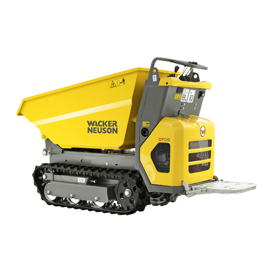
1. 2 Overall view of vehicle Control stand/handle Tipping Trailer Hydraulic motor Travel drive Lifting eye/tie-down point Chassis Track Foothold Engine cover 10 Wheel chock 11 Loader unit (option) Fig. 1: Vehicle outside views BA DT05 EN - Edition 2.0 * * dt05b110.fm... -
Page 11: Brief Description
• Tracked travel gear • Control stand • Internal combustion engine • Model DT05-P: single-cylinder petrol engine (up to series FB05777) • Model DT05-P: single-cylinder petrol engine according to the standard EPA Tier 4 / Stage V (from series FC05835) •... -
Page 12: Regulations
• Persons are expected to perform work reliably. They have been appointed by the contractor for driving and servicing the earth moving machine. Observe the legal regulations of your country. BA DT05 EN - Edition 2.0 * * dt05b110.fm... -
Page 13: Ec Declaration Of Conformity Model Dt05-P, For Vehicles With Ce Mark On The Type Label (Up To Series Fb05777)
Introduction 1. 5 EC Declaration of Conformity model DT05-P, for vehicles with CE mark on the type label (up to series FB05777) EC Declaration of Conformity Manufacturer Messersì, Via Arceviese, 44, 60010 Casine di Ostra, Ancona - Italy Product Machine designation... -
Page 14: Ec Declaration Of Conformity Model Dt05-P, For Vehicles With Ce Mark On The Type Label (From Series Fc05835)
Introduction 1. 6 EC Declaration of Conformity model DT05-P, for vehicles with CE mark on the type label (from series FC05835) EC Declaration of Conformity Manufacturer Messersì, Via Arceviese, 44, 60010 Casine di Ostra, Ancona - Italy Product Machine designation... -
Page 15: Ec Declaration Of Conformity Model Dt05-D, For Vehicles With Ce Mark On The Type Label (Up To Series Fb05880)
Introduction 1. 7 EC Declaration of Conformity model DT05-D, for vehicles with CE mark on the type label (up to series FB05880) EC Declaration of Conformity Manufacturer Messersì, Via Arceviese, 44, 60010 Casine di Ostra, Ancona - Italy Product Machine designation... -
Page 16: Ec Declaration Of Conformity Model Dt05-D, For Vehicles With Ce Mark On The Type Label (From Series Fc05909)
Introduction 1. 8 EC Declaration of Conformity model DT05-D, for vehicles with CE mark on the type label (from series FC05909) EC Declaration of Conformity Manufacturer Messersì, Via Arceviese, 44, 60010 Casine di Ostra, Ancona - Italy Product Machine designation... -
Page 17: Type Labels And Component Numbers
The type label (arrow) is located next to the oil check plug. Fig. 2: Engine number (petrol engine) The type label (arrow) is located below the tank (engine). Fig. 3: Diesel engine number BA DT05 EN – Edition 2.0 * dt05b110.fm... -
Page 18: Signs And Symbols
Introduction 1. 10 Signs and symbols 1-10 BA DT05 EN - Edition 2.0 * * dt05b110.fm... - Page 19 Machine Directive and that the conformity procedure has been performed. The machine meets all the health and safety requirements of the Machine Directive. Application Fig. 9: CE mark On the type label 1-11 BA DT05 EN – Edition 2.0 * dt05b110.fm...
- Page 20 Fig. 16: Hot surfaces Meaning Danger due to components under spring tension! Indicates the device for adjusting track tension. Application Fig. 17: Track tension adjustment Right and left side of chassis 1-12 BA DT05 EN - Edition 2.0 * * dt05b110.fm...
- Page 21 Introduction Meaning This label explains the machine’s control elements – see chapter 3. 1 Overview of control stand (type DT05-P skip) on page 3-2 Application Fig. 18: Main label On the control stand Meaning Indication of throttle. Application On the control stand Fig.
- Page 22 Introduction 1-14 BA DT05 EN - Edition 2.0 * * dt05b110.fm...
-
Page 23: Safety Instructions
These types of dangers may be due to improper disposal of environmentally hazardous substances (e.g. waste oil). 2. 2 Warranty Warranty claims can be brought forward to your Wacker Neuson dealer only. Furthermore, the instructions in this Operator’s Manual must be observed. 2. 3 Disposal All fluids, lubricants, material, etc., used on the machine are subject to specific... -
Page 24: Designated Use And Exemption From Liability
Wacker Neuson shall not be liable for damage resulting from this and the risk shall be fully borne by the user. Designated use also includes observing the instructions set forth in the Operator’s Manual and observing the maintenance and service conditions. - Page 25 (for example operator's cab, loading platform, etc.), as well as to the attachments, which might affect safety without the approval of Wacker Neuson! This also applies to the installation and the adjustment of safety devices and valves, as well as to welding work on load-bearing elements.
-
Page 26: Selection And Qualification Of Personnel, Basic Responsibilities
• this also includes the area affected by falling material, equipment or by debris that is thrown out. The danger area must be extended by 0.5 m in the immediate vicinity • buildings • scaffolds or • other elements of construction BA DT05 EN - Edition 2.0 * * dt05b210.fm... -
Page 27: Safety Instructions Regarding Operation
• When working in buildings or in enclosed areas, look out for in particular: • Height of the ceiling/clearances • Width of entrances • Maximum load of ceilings and floors • Sufficient room ventilation – poisoning hazard! BA DT05 EN – Edition 2.0 * dt05b210.fm... - Page 28 • Never get on or off a moving machine! Never jump off the machine! • The drive levers take time getting used to them. Therefore, adjust the travel speed to your abilities and the circumstances. BA DT05 EN - Edition 2.0 * * dt05b210.fm...
-
Page 29: Applications With Lifting Gear
Operator’s Manual, and the information on maintenance • If required, secure the maintenance area appropriately! BA DT05 EN – Edition 2.0 * dt05b210.fm... - Page 30 – must be protected against water, steam or detergent penetration. Special care must be taken with the electrical system. • After cleaning, remove all covers and tapes applied for that purpose! BA DT05 EN - Edition 2.0 * * dt05b210.fm...
-
Page 31: Warning Of Special Hazards
• Inspect and check the electric equipment of the machine at regular intervals. Malfunctions such as loose connections or scorched cables must be rectified immediately • Observe the machine’s operating voltage! BA DT05 EN – Edition 2.0 * dt05b210.fm... -
Page 32: Gas, Dust, Steam, Smoke
Observe the regulations in force at the respective site! • Welding, burning and grinding work on the machine may only be performed by a Wacker Neuson dealer. Risk of fire and explosion! • Before performing welding, flame-cutting and grinding work, clean the... -
Page 33: Track
Wacker Neuson service center only! • Malfunctioning tracks reduce the machine’s operational safety. Therefore perform regular checks of the tracks for • Cracks, cuts or other damage • Check track tension at regular intervals. 2-11 BA DT05 EN – Edition 2.0 * dt05b210.fm... - Page 34 Safety instructions 2-12 BA DT05 EN - Edition 2.0 * * dt05b210.fm...
-
Page 35: Operation
40/control element no. 18, or position A in figure no. 40 Figures carry no numbers if they are placed to the left of the text. BA DT05 EN – Edition 2.0 * dt05b320.fm... -
Page 36: Overview Of Control Stand (Type Dt05-P Skip)
Operation 3. 1 Overview of control stand (type DT05-P skip) Pos. Definition For more information see page ...........................3-21 Skip operation .........................3-14 Normal or high speed lever ..........................3-14 Drive lever (left) ..........................3-14 Drive lever (right) 3-14 Throttle ................................Lock for cover... -
Page 37: Overview Of Control Stand (Type Dt05-D Skip)
Operation 3. 2 Overview of control stand (type DT05-D skip) Pos. Definition For more information see page ..........................3-21 Skip operation .........................3-14 Normal or high speed lever ..........................3-14 Drive lever (left) ..........................3-14 Drive lever (right) 3-14 Throttle................................Hour meter 3-10 Ignition lock.............................. -
Page 38: Overview Of The Control Stand (Type Dt05 High Skip) (Optional) / Loader Unit (Optional)
Operation 3. 3 Overview of the control stand (type DT05 high skip) (optional) / Loader unit (optional) Pos. Definition For more information see page ...........................3-31 Skip operation ....................3-20,3-31 Skip lifting/loader unit operation 8 Alternator charge function indicator light Attention! -
Page 39: Putting Into Operation
• Strictly observe the maintenance schedules in the appendix – see chapter 5. 10 Maintenance plan DT05-P (gasoline engine) on page 5-30 – see chapter 5. 11 Maintenance plan DT05-D (diesel engine) on page 5-32 BA DT05 EN – Edition 2.0 * dt05b320.fm... -
Page 40: Check Lists
Loader unit (option) lowered to the ground? ( 3-20) When parking on public roads: Machine appropriately secured? When parking on slopes: Machine also secured with chocks under the tracks to prevent it from rolling away? BA DT05 EN - Edition 2.0 * * dt05b320.fm... -
Page 41: Before Starting The Engine
Do not use choke lever B if the engine is warm or at high air tempera- tures. Fig. 22: Fuel cock Push throttle 5 slightly forwards Fig. 23: Throttle Turn the engine switch to position E Fig. 24: Engine switch BA DT05 EN – Edition 2.0 * dt05b330.fm... -
Page 42: Manual Starter
Push throttle 1 fully backward The engine remains stationary Fig. 27: Throttle Turn the engine switch to position B Fig. 28: Engine switch Turn fuel cock D to the right Fig. 29: Fuel cock BA DT05 EN - Edition 2.0 * * dt05b330.fm... -
Page 43: General Informationen On Starting The Diesel Engine
After you have completed the starting preparations: Turn fuel cock A clockwise to position O The fuel cock is open Fig. 30: Fuel cock Push throttle 5 fully to the front Fig. 31: Throttle BA DT05 EN – Edition 2.0 * dt05b330.fm... -
Page 44: Manual Starter
Contact a Wacker Neuson service center for troubleshooting As soon as the engine runs: Release the starting key. Warning! Do not actuate the electric starter for more than 5 seconds. Fig. 34: Start 3-10 BA DT05 EN - Edition 2.0 * * dt05b330.fm... -
Page 45: Starting At Low Temperatures
When the engine has started Let the engine run warm At cold temperatures: Increase the engine speed slowly Do not run the engine at full load until it has reached its operating tem- perature 3-11 BA DT05 EN – Edition 2.0 * dt05b330.fm... -
Page 46: Stopping The Diesel Engine
Fig. 35: Throttle Turn starter B to position E Fig. 36: Electric starter Turn fuel cock F anticlockwise to position S Fig. 37: Fuel cock 3-12 BA DT05 EN - Edition 2.0 * * dt05b330.fm... -
Page 47: Jump-Starting The Engine (Supply Battery)
Warning! Operation of electric consumers (for example the lighting equipment) is prohibited. This is why the vehicle has no socket. Also observe the applicable regulations for accident prevention of your country. 3-13 BA DT05 EN – Edition 2.0 * dt05b330.fm... -
Page 48: Starting Vehicle Travel
Pull lever 2 backwards. The machine now moves at lower speed Warning! Ensure that both tracks move as you change direction, otherwise the rubber tracks are subject to increased abrasion. 3-14 BA DT05 EN - Edition 2.0 * * dt05b330.fm... -
Page 49: Machine Travel On Slopes
The machine can slip even if the ground is level. If the engine stops as you drive across a slope, immediately put the control levers to neutral position and start the engine again. 3-15 BA DT05 EN – Edition 2.0 * dt05b330.fm... -
Page 50: Transverse Driving On A Slope
Machine travel is allowed on firm ground on a slope of up to 15°. max. 15° Fig. 41: Machine travel with an empty machine on slopes < 15° Fig. 41: Machine travel with a load on slopes 3-16 BA DT05 EN - Edition 2.0 * * dt05b330.fm... - Page 51 Due to the reduced width, proceed with extreme care during machine travel on slopes, and on soft and uneven ground. Drive with extreme care on slopes in rain or if the ground is wet or slippery. 3-17 BA DT05 EN – Edition 2.0 * dt05b330.fm...
-
Page 52: Driving On Slopes With A High-Tip Skip
Driving with a raised and tilted skip is forbidden. Raise and dump out the skip only if the machine is at a standstill. Fig. 43: Driving with a high-tip skip 3-18 BA DT05 EN - Edition 2.0 * * dt05b330.fm... -
Page 53: Skip
• B 12 pulled backwards Skip is tilted in • E 13 pushed forwards Skip is lowered Fig. 45: Operating the high-tip skip • F 13 pulled backwards Skip is raised 3-19 BA DT05 EN – Edition 2.0 * dt05b330.fm... -
Page 54: Loader Unit Operation (Option)
Loader unit is lowered • B 1 pulled backward Loader unit is raised Warning! Always keep the loader unit 30 – 40 cm above the ground during machine operation. Fig. 46: Loader unit 3-20 BA DT05 EN - Edition 2.0 * * dt05b330.fm... -
Page 55: Machine Shut-Down
Remove the starting key. Attention! Never stop the engine under full load. Let the engine run at idling speed for at least 1 minute before switching it off. Fig. 47: Wheel chock 3-21 BA DT05 EN – Edition 2.0 * dt05b330.fm... -
Page 56: Foothold
Fig. 48: Folding up the foothold Folding down the foothold: Grab the foothold A with both hands. Fold it down to the horizontal position. Fig. 49: Folding down the foothold 3-22 BA DT05 EN - Edition 2.0 * * dt05b330.fm... -
Page 57: Crane-Lifting The Machine
Length L1 of the lifting gear on the skip must be at least 2.0 m long Length L2 of the lifting gear (two cables or chains) on the control stand must be at least 2.0 m long • Slowly raise the machine Fig. 50: Crane-lifting 3-23 BA DT05 EN – Edition 2.0 * dt05b330.fm... -
Page 58: Loading And Transporting The Machine
Carefully drive the dumper onto the middle of the transport vehicle. Stop the engine. Remove the ignition key (model DT05-D) Warning! The manufacturer’s warranty shall not apply to accidents or dam- age caused by loading or transporting. 3-24 BA DT05 EN - Edition 2.0 * * dt05b330.fm... -
Page 59: Tying Down The Machine
Tie down the machine. Fig. 52: Tying down the dumper 3-25 BA DT05 EN – Edition 2.0 * dt05b330.fm... -
Page 60: Towing The Machine
The manufacturer’s warranty shall not apply to accidents or dam- age caused by towing. Using the tie-down eyelets for towing another machine is prohibited. The machine can also be salvaged with a crane. Fig. 53: Towing the vehicle 3-26 BA DT05 EN - Edition 2.0 * * dt05b330.fm... -
Page 61: Machine Operation
Transporting with a full bucket Attention! No transport of material: the loader unit is designed for loading loose material only. Loading loose material is described below Only load material with the skip tilted in 3-27 BA DT05 EN – Edition 2.0 * dt05b340.fm... -
Page 62: Loading Loose Material
• Reduce the load on the loader unit by reversing Fig. 55: Driving into the material Ending loading Set the loader unit to position C Move the control lever 1 D backwards Fig. 56: Tilt in the loader unit 3-28 BA DT05 EN - Edition 2.0 * * dt05b340.fm... -
Page 63: Transporting With A Full Skip
Fully tilt in the skip A Lower the loader unit (option) to transport position B Always reverse up a slope at low speed with a full skip Fig. 58: Transporting with a full skip 3-29 BA DT05 EN – Edition 2.0 * dt05b340.fm... -
Page 64: Tilt Out The Skip
Always select the optimal position for the loader unit Fig. 59: Tilt out the skip 3-30 BA DT05 EN - Edition 2.0 * * dt05b340.fm... -
Page 65: Empty The High Tip Skip (Optional)
Lower the skip by hand downwards to over the pivot point B and at the same time pull the lever 1 A to the rear The skip is lowered by its own weight once it is beyond the pivot point 3-31 BA DT05 EN – Edition 2.0 * dt05b340.fm... - Page 66 Operation 3-32 BA DT05 EN - Edition 2.0 * * dt05b340.fm...
-
Page 67: Engine Malfunctions
Malfunctioning ignition (DT05-P only) Malfunctioning spark plugs (DT05-P only) Oil level too low 5-11 Insufficient or no engine oil pressure Excessive machine inclination (max. 15°) Wrong SAE grade of engine lubrication oil 5-29 BA DT05 EN – Edition 2.0 * dt05b410.fm... - Page 68 Engine starting temperature too low Fuel grade does not comply with specifications 5-29 White Engine smoke Wrong valve clearance Malfunctioning fuel injector Polluted air filter 5-14 Black Wrong valve clearance Malfunctioning fuel injector BA DT05 EN - Edition 2.0 * * dt05b410.fm...
-
Page 69: Maintenance
Secure the maintenance prop A with the lock pin C and the pin D. During transport fit maintenance strut A as shown in Fig. 62 – transport strut. Fig. 62: Maintenance prop BA DT05 EN – Edition 2.0 * dt05b510.fm... -
Page 70: Maintenance Strut For High-Tip Skip
The skip is blocked in the raised position. Remove the safety strut and the pin from opening B and insert them in opening C. The skip is blocked in the raised position Fig. 63: Maintenance strut BA DT05 EN - Edition 2.0 * * dt05b510.fm... -
Page 71: Fuel System
If the fuel level is below min. Filling up with fuel min. Warning! The vehicle has no filling level indicator, therefore always check the Fig. 65: Model DT05-D (diesel engine) fuel level before putting the vehicle into operation. BA DT05 EN – Edition 2.0 * dt05b510.fm... -
Page 72: Refuelling
• Wait for a moment (about 3 minutes) until the oil has been completely drained from the tank • Refit seal B and close filler cap C. Fit seal D and filter cup E back on again Fig. 67: Draining fuel (gasoline engine) BA DT05 EN - Edition 2.0 * * dt05b510.fm... - Page 73 Never perform work on the fuel system near open flames or sparks. Environment! Use a suitable container to collect the fuel as it drains and dis- pose of it in an environmentally friendly manner! BA DT05 EN – Edition 2.0 * dt05b510.fm...
-
Page 74: Draining Fuel (Diesel Engine)
• Only fill the tank using refueling aids (funnels or filler pipes) with integral micro-filter • All vessel for refueling must always be kept clean. Fig. 70: Refuelling from a barrel BA DT05 EN - Edition 2.0 * * dt05b510.fm... -
Page 75: Gasoline Specification
Allow filter cup A to dry thoroughly Screw filter cup A back on again with a suitable tool Set the fuel cock to ON and check for leaks Fig. 71: Filter cup DT05-P (gasoline engine) BA DT05 EN – Edition 2.0 * dt05b510.fm... -
Page 76: Cleaning The Fuel Filter (Gasoline Engine)
Fit seal B on the filter and install it again Specific torque 2 Nm Check for possible leaks Environment! Dispose of the drained fuel in an environmentally friendly manner. Fig. 72: Cleaning the DT05-P filter (gasoline engine) BA DT05 EN - Edition 2.0 * * dt05b510.fm... -
Page 77: Cleaning The Fuel Filter Of The Diesel Engine
Fit fuel cock C back on again by tightening screws B. Use a new seal D as you do so Environment! Dispose of the drained fuel in an environmentally friendly manner. Fig. 74: Cleaning the inside filter DT05-D (diesel engine) BA DT05 EN – Edition 2.0 * dt05b510.fm... -
Page 78: Spark Plug (Petrol Engine)
Tighten an old spark plug B by 1/8 – 1/4 of a revolution after it makes contact, in order to compress the sealing ring Fit spark plug connector A back on again We recommend the following spark plugs: Manufacturer’s description Manufacturer • BPR5ES • BPR6ES 5-10 BA DT05 EN - Edition 2.0 * * dt05b510.fm... -
Page 79: Engine Lubrication System
If the engine oil level is too high or too low, if the wrong oil is used or if an oil change is overdue, this can cause Engine damage and loss of output! Have the oil changed by a Wacker Neuson service center – see chapter 5. 10 Maintenance plan DT05-P (gasoline engine) on page 5-30 –... -
Page 80: Filling Up Engine Oil
Fig. 78: Draining engine oil (gasoline engine) Close filler cap B Specific torque DT05-D (diesel engine) 19.6 – 23.5 Nm Environment! Use a suitable container to collect the engine oil as it drains and dispose of it in an environmentally friendly manner! Fig. -
Page 81: Cleaning/Replacing The Engine Oil Filter (Diesel Engine)
Screw in screw B and tighten it to fasten the engine oil filter Refill with engine oil Environment! Dispose of the drained fuel in an environmentally friendly manner. Fig. 79: Cleaning/replacing the DT05-D engine oil filter (diesel engine) 5-13 BA DT05 EN – Edition 2.0 * dt05b510.fm... -
Page 82: Air Filter
Replace the filter cartridge A after 50 hours run at the latest! Fig. 80: Air filter (diesel engine) 5-14 BA DT05 EN - Edition 2.0 * * dt05b520.fm... -
Page 83: Replacing The Filter (Gasoline Engine)
Position cover C (ensure that it is properly seated) Tighten wing nut B again on cover C Environment! Dispose of filter cartridge A in an environmentally friendly manner. Fig. 82: Replacing the DT05-P filter (petrol engine) 5-15 BA DT05 EN – Edition 2.0 * dt05b520.fm... -
Page 84: Replacing The Filter (Diesel Engine)
The filter cartridge of the diesel engine cannot be cleaned. Replace it if it is malfunctioning or according to the maintenance interval. Fig. 83: Replacing the air filter (diesel engine) 5-16 BA DT05 EN - Edition 2.0 * * dt05b520.fm... -
Page 85: Hydraulic System
Collect drained hydraulic oil and biodegradable oil in a suitable container! Dispose of drained oil and used filters by an ecologically safe method. Always contact the relevant authorities or commercial establishments in charge of oil disposal before disposing of biodegradable oil. 5-17 BA DT05 EN – Edition 2.0 * dt05b520.fm... -
Page 86: Checking The Hydraulic Oil Level
With the filter insert in place: Adding hydraulic oil Check the hydraulic oil level with the dipstick integrated in filler cap B Add if necessary and check again Firmly tighten filler cap B by hand. 5-18 BA DT05 EN - Edition 2.0 * * dt05b520.fm... -
Page 87: Drain Hydraulic Oil
Collect the drained oil in a suitable container and dispose of it by an eco- logically safe method! Environment! Dispose of filter cartridge A in an environmentally friendly man- ner. Fig. 87: Replacing the oil filter cartridge 5-19 BA DT05 EN – Edition 2.0 * dt05b520.fm... -
Page 88: Important Information For The Use Of Biodegradable Oil
Important information for the use of biodegradable oil • Use only the biodegradable hydraulic fluids which have been tested and approved by Wacker Neuson. Always contact Wacker Neuson for the use of other products that have not been recommended. In addition, ask the oil supplier for a written declaration of guarantee. -
Page 89: Checking Hydraulic Pressure Lines
• Have damaged flexible lines replaced by service centers only! • Leaks and damaged pressure lines must be immediately repaired or replaced by a Wacker Neuson service center or after-sales personnel. This not only increases the operating safety of the vehicle but also helps to protect the environment. -
Page 90: Tracks
Repeat the procedure if the tracks are not tight enough. Warning! Check track tension once a day since excessive or insufficient track tension can damage the tracks and the components of the under- carriage. 5-22 BA DT05 EN - Edition 2.0 * * dt05b530.fm... -
Page 91: Decreasing Track Tension
Fig. 90: Loosen the chain Unscrew adjusting screw D with a suitable tool. Ram E is retracted The track is loosened Check track tension Repeat the procedure if the tracks are too tight. 5-23 BA DT05 EN – Edition 2.0 * dt05b530.fm... -
Page 92: Electrical System
Servicing and maintenance at regular intervals Every week Check once a week: • Electric fuses • Cable and grounding connections • Battery charge condition – see Battery on page 5-26 • Condition of battery terminals 5-24 BA DT05 EN - Edition 2.0 * * dt05b530.fm... -
Page 93: Instructions Concerning Specific Components
Electric lines and fuses Always observe the following warnings: • Malfunctioning components of the electrical system must always be replaced by a Wacker Neuson service center. Fuses may be changed by unqualified persons. • When performing maintenance work on the electrical system, pay particular attention to ensuring good contact in leads. -
Page 94: Battery
• Firmly pull cable C to disconnect the battery in an emergency. Warning! Firmly pull cable C in an emergency only since this damages the electric line and possibly the starter. Fig. 92: Battery 5-26 BA DT05 EN - Edition 2.0 * * dt05b530.fm... -
Page 95: General Maintenance
• Air intake filters, etc. Cleaning with volatile and easily flammable anticorrosion agents and sprays: • Ensure sufficient room ventilation. • Do not use unprotected lights or open flames. • Do not smoke! 5-27 BA DT05 EN – Edition 2.0 * dt05b530.fm... - Page 96 Pivots and hinges Lubricate all mechanical pivots on the machine (such as joints) and fittings at regular intervals even if they are not listed in the lubrication plan. 5-28 BA DT05 EN - Edition 2.0 * * dt05b530.fm...
- Page 97 Biodegradable hydraulic oils based on saturated synthetic esters with an iodine value of < 10 according to DIN 51524, section 3, HVLP, HEES KF2K-25 according to DIN 51502 multipurpose lithium grease with MoS² additive Unleaded regular 5-29 BA DT05 EN – Edition 2.0 * dt05b530.fm...
- Page 98 Customer Every 3 years and/or after 1000 Every 12 months or after 500 Every 6 months or after 250 Once a month or after 50 o/h Service work (daily) 5-30 BA DT05 EN - Edition 2.0 * * dt05b540.fm...
- Page 99 Customer Every 3 years and/or after 1000 Every 12 months or after 500 Every 6 months or after 250 Once a month or after 50 o/h Service work (daily) 5-31 BA DT05 EN – Edition 2.0 * * dt05b540.fm...
- Page 100 Customer Every 3 years and/or after 1000 Every 12 months or after 500 Every 6 months or after 250 Once a month or after 50 o/h Service work (daily) 5-32 BA DT05 EN - Edition 2.0 * * dt05b550.fm...
- Page 101 Customer Every 3 years and/or after 1000 Every 12 months or after 500 Every 6 months or after 250 Once a month or after 50 o/h Service work (daily) 5-33 BA DT05 EN – Edition 2.0 * * dt05b550.fm...
-
Page 102: Lubrication Plan Dt05 With Skip
Maintenance Maintenance 5. 12 Lubrication plan DT05 with skip Explanation Symbol Grease nipples 5-34 BA DT05 EN - Edition 2.0 * * dt05b560.fm... -
Page 103: Lubrication Plan Of Dt05 With High Tip Skip (Optional)
Maintenance 5. 13 Lubrication plan of DT05 with high tip skip (optional) Explanation Symbol Grease nipples 5-35 BA DT05 EN – Edition 2.0 * dt05b560.fm... -
Page 104: Lubrication Plan Dt05 With Skip And Loader Unit (Optional)
Maintenance 5. 14 Lubrication plan DT05 with skip and loader unit (optional) Explanation Symbol Grease nipples 5-36 BA DT05 EN - Edition 2.0 * * dt05b560.fm... -
Page 105: Maintenance Opening
Maintenance Maintenance opening Maintenance opening for cleaning the chassis. Unscrew 4 screws to remove housing A. Fig. 93: Maintenance opening 5-37 BA DT05 EN – Edition 2.0 * dt05b560.fm... - Page 106 Maintenance 5-38 BA DT05 EN - Edition 2.0 * * dt05b560.fm...
-
Page 107: Technical Data
Technical data 6 Technical data 6. 1 Engine (DT05-P up to series FB05777)(DT05-D up to series FB05880) Sturdy steel sheet frame, rubber-mounted engine Model DT05-D Model DT05-P Hydraulic motor Yanmar diesel Honda gasoline Product engine engine L70N6 CA1T1AAS1 GX 200 UT-QX-9-OH... -
Page 108: Engine (Dt05-P From Series Fc05835)(Dt05-D From Series Fc05909)
Technical data 6. 2 Engine (DT05-P from series FC05835)(DT05-D from series FC05909) Sturdy steel sheet frame, rubber-mounted engine Model DT05-D Model DT05-P Hydraulic motor Yanmar diesel Honda gasoline Product engine engine L70V6 CA1T1AAS1 GX 200 UT Type Air-cooled 4-stroke engine... -
Page 109: Hydraulic System
1 section/2 sections Control Unit Max. operating pres- ±5 ±5 sure for work operation Max. operating pres- ±5 sure for drive operation Return filter Filter 15 l Hydraulic oil reservoir BA DT05 EN – Edition 2.0 * dt05b610.fm... -
Page 110: Electrical System
Length of the tipper 589 mm Width of the tipper 386 mm Height of the tipper 6. 8 High-tip skip (option) (Up to series FB04439 for the DT05-D and up to series FB04419 for the DT05-P) Front tip skip Model DT05-D Model DT05-P... -
Page 111: Self-Loading Equipment (Optional)
6. 13 Fuses Fuse Rated current (A) Model DT05-D - diesel engine 20 A Fig. 94: Diesel engine fuse BA DT05 EN – Edition 2.0 * dt05b610.fm... -
Page 112: Dimensions Model Dt05-D With Skip
Chain length 399 mm Front skip projection 759 mm Skip load height (front edge) 1280 mm Length of the tipper 589 mm Width of the tipper 386 mm Depth of the tipper BA DT05 EN - Edition 2.0 * * dt05b610.fm... -
Page 113: Dimensions Model Dt05-D With Skip And Loader Unit (Option)
Technical data 6. 15 Dimensions model DT05-D with skip and loader unit (option) 1310 1670 2514 Fig. 96: Machine dimensions (model DT05-D with skip and loader unit) Model DT05-D Main data 500 kg Payload 545 kg Dead weight incl. skip and loader unit... -
Page 114: Dimensions Model Dt05-D With High-Tip Skip (Option) (Up To Series Fb04439)
Technical data 6. 16 Dimensions model DT05-D with high-tip skip (option) (Up to series FB04439) 1120 1550 Fig. 97: Machine dimensions (model DT05-D with high-tip skip) Model DT05-D Main data 400 kg Payload 520 kg Dead weight, skip 1550 mm... -
Page 115: Dimensions Model Dt05-D With High-Tip Skip (Option) (From Series Fb05432)
Technical data 6. 17 Dimensions model DT05-D with high-tip skip (option) (from series FB05432) 1278 1619 Fig. 98: Machine dimensions (model DT05-D with high-tip skip) Model DT05-D Main data 400 kg Payload 530 kg Dead weight, skip 1619 mm Length... -
Page 116: Dimensions Model Dt05-P With Skip
399 mm Front skip projection 760 mm Skip load height (front edge) 1280 mm Length of the tipper 589 mm Width of the tipper 386 mm Depth of the tipper 6-10 BA DT05 EN - Edition 2.0 * * dt05b610.fm... -
Page 117: Dimensions Model Dt05-P With Skip And Loader Unit (Option)
Technical data 6. 19 Dimensions model DT05-P with skip and loader unit (option) 1310 1629 2470 Fig. 100:Machine dimensions (model DT05-P with skip and loader unit) Model DT05-P Main data 500 kg Payload 500 kg Dead weight incl. skip and loader unit... -
Page 118: Dimensions Model Dt05-D With High Tip Skip (Optional (Up To Series Fb04419)
Technical data 6. 20 Dimensions model DT05-D with high tip skip (optional (up to series FB04419) 1120 1510 Fig. 101:Machine dimensions (model DT05-P with high-tip skip) Model DT05-P Main data 400 kg Payload 475 kg Dead weight, skip 1510 mm... -
Page 119: Dimensions Model Dt05-D With High Tip Skip (Optional) (From Series Fb05398 Including Fb04332)
Technical data 6. 21 Dimensions model DT05-D with high tip skip (optional) (from series FB05398 including FB04332) 1278 1578 Fig. 102:Machine dimensions (model DT05-P with high-tip skip) Model DT05-P Main data 400 kg Payload 485 kg Dead weight, skip 1578 mm... - Page 120 Technical data 6-14 BA DT05 EN - Edition 2.0 * * dt05b610.fm...
- Page 121 Wacker Neuson Linz GmbH keep abreast of the latest technical develop- ments and constantly improve their products. For this reason, we may from time to time need to make changes to figures and descriptions in this docu- mentation that do not reflect products that have already been delivered and that will not be implemented on these vehicles.
- Page 122 Wacker Neuson Linz GmbH Flughafenstraße 7 A-4063 Hörsching Austria Tel. +43 (0) 7221 63000-0 Fax: +43 (0) 7221 63000- 4000 E-mail office.linz@wacker- neuson.com www.wackerneuson.com Order no. 1000268362 Language en...
Need help?
Do you have a question about the DT05 and is the answer not in the manual?
Questions and answers