Table of Contents
Advertisement
Quick Links
Advertisement
Table of Contents

Related Manuals for Supermicro SUPERSERVER 6036ST-6LR


Summary of Contents for Supermicro SUPERSERVER 6036ST-6LR
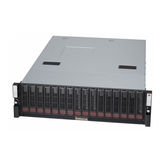
- Page 1 ® UPER 6036ST-6LR UPER ERVER USER’S MANUAL 1.0c...
- Page 2 The information in this User’s Manual has been carefully reviewed and is believed to be accurate. The vendor assumes no responsibility for any inaccuracies that may be contained in this document, makes no commitment to update or to keep current the information in this manual, or to notify any person or organization of the updates.
-
Page 3: About This Manual
SuperServer 6036ST-6LR. Installation and maintainance should be performed by experienced technicians only. The SuperServer 6036ST-6LR is a high-end storage server solution based on the SC937 3U rackmount chassis and the X8DTS-F dual processor serverboard. Manual Organization Chapter 1: Introduction The fi... - Page 4 UPER ERVER 6036ST-6LR User's Manual Chapter 5: Advanced Serverboard Setup Chapter 5 provides detailed information on the X8DTS-F serverboard, including the locations and functions of connections, headers and jumpers. Refer to this chapter when adding or removing processors or main memory and when reconfi guring the serverboard.
- Page 5 Preface Notes...
-
Page 6: Table Of Contents
UPER ERVER 6036ST-6LR User's Manual Table of Contents Chapter 1 Introduction Overview ......................1-1 Serverboard Features ..................1-2 Processors ...................... 1-2 Memory ......................1-2 SAS ........................ 1-2 SATA ......................1-2 PCI Expansion Slots ..................1-2 Rear Chassis Ports ..................1-3 Graphics Controller .................. - Page 7 Table of Contents Installing the Chassis into a Rack..............2-6 Checking the Serverboard Setup ..............2-7 Checking the Drive Bay Setup ................ 2-9 Chapter 3 System Interface Overview ......................3-1 Control Panel Button ..................3-1 Control Panel LEDs ..................3-1 Drive Carrier LEDs ..................
- Page 8 UPER ERVER 6036ST-6LR User's Manual DIMM Installation .................... 5-6 Installing PCI Add-On Cards ................5-8 Serverboard Details ..................5-10 X8DTS-F Quick Reference ................5-11 Connector Defi nitions ................... 5-12 Jumper Settings .................... 5-14 Onboard Indicators ..................5-16 5-10 Installing Software ..................5-17 SuperDoctor III ....................
-
Page 9: Chapter 1 Introduction
Chapter 1 Introduction Overview The SuperServer 6036ST-6LR is a high-end Super Storage Bridge Bay (SBB) sys- tem comprised of two main subsystems: the SC937 chassis and two X8DTS-F dual processor serverboards. Please refer to our web site for information on operating systems that have been certifi... -
Page 10: Serverboard Features
ERVER 6036ST-6LR User's Manual Serverboard Features The SuperServer 6036ST-6LR is built around two X8DTS-F serverboards for a dual-node system. The X8DTS-F is a dual processor serverboard based on the Intel® 5520 chipset (5520/IOH-36D + ICH10). Below are the main features of the X8DTS-F. -
Page 11: Rear Chassis Ports
SAS/SATA drives. Front Control Panel Two control panels are included on each end of the SuperServer 6036ST-6LR to provide you with system monitoring and control. LEDs indicate system power, network (NIC) activity, system overheat and power supply failure. Each set of LEDs are associated with the node/serverboard on the same side of the chassis. -
Page 12: Cooling System
UPER ERVER 6036ST-6LR User's Manual Cooling System The SC937 chassis has six fans: three at the front and another three at the rear (consisting of two sets of three 4-cm counter-rotating fans). This counter-rotating action works to dampen vibration levels while generating exceptional airfl ow. Two additonal pairs of counter-rotating fans are included at the rear of each of the two nodes/serverboards. -
Page 13: Contacting Supermicro
Chapter 1: Introduction Contacting Supermicro Headquarters Address: Super Micro Computer, Inc. 980 Rock Ave. San Jose, CA 95131 U.S.A. Tel: +1 (408) 503-8000 Fax: +1 (408) 503-8008 Email: marketing@supermicro.com (General Information) support@supermicro.com (Technical Support) Web Site: www.supermicro.com Europe Address: Super Micro Computer B.V. Het Sterrenbeeld 28, 5215 ML 's-Hertogenbosch, The Netherlands Tel:... -
Page 14: Sbb: Storage Bridge Bay
UPER ERVER 6036ST-6LR User's Manual SBB: Storage Bridge Bay The 6036ST-6LR Super SBB was designed to function as a fully redundant, fault- tolerant "cluster-in-a-box" system. The standard support for 16 3.5" hot-swap HDDs (SAS1, SAS2 or Enterprise SATA) may be expanded to support an additional 16 HDDs with the optional SBB JBOD SYS-937R-E2JB confi... -
Page 15: Chapter 2 Server Installation
Unpacking the System You should inspect the box the SuperServer 6036ST-6LR was shipped in and note if it was damaged in any way. If the server itself shows damage you should fi le a damage claim with the carrier who delivered it. -
Page 16: Warnings And Precautions
UPER ERVER 6036ST-6LR User's Manual • This product is for installation only in a Restricted Access Location (dedicated equipment rooms, service closets and the like). • This product is not suitable for use with visual display work place devices acccording to §2 of the the German Ordinance for Work with Visual Display Units. -
Page 17: Rack Mounting Considerations
Chapter 2: Server Installation Rack Mounting Considerations Ambient Operating Temperature If installed in a closed or multi-unit rack assembly, the ambient operating tempera- ture of the rack environment may be greater than the ambient temperature of the room. Therefore, consideration should be given to installing the equipment in an environment compatible with the manufacturer’s maximum rated ambient tempera- ture (Tmra). -
Page 18: Installing The System Into A Rack
UPER ERVER 6036ST-6LR User's Manual Installing the System into a Rack This section provides information on installing the SC937 chassis into a rack unit with the quick-release rails provided. There are a variety of rack units on the market, which may mean the assembly procedure will differ slightly. You should also refer to the installation instructions that came with the rack unit you are using. -
Page 19: Installing The Outer Rack Rails
Chapter 2: Server Installation Installing the Outer Rack Rails Outer rails attach to the server rack and hold the server in place. The outer rails for the SC937 chassis extend between 30 inches and 33 inches. Installing the Outer Rails 1. -
Page 20: Installing The Chassis Into A Rack
UPER ERVER 6036ST-6LR User's Manual Figure 2-3. Installing the Chassis into the Rack Installing the Chassis into a Rack Installing into a Rack 1. Confi rm that the inner and outer rails are properly installed. 2. Line up the inner (chassis) rails with the front of the outer (rack) rails. 3. -
Page 21: Checking The Serverboard Setup
Chapter 2: Server Installation Checking the Serverboard Setup After you install the 6036ST-6LR in the rack, you will need to open the unit to make sure the serverboard is properly installed and all the connections have been made. Accessing the Inside of the System (Figure 2-4) 1. - Page 22 UPER ERVER 6036ST-6LR User's Manual Figure 2-4. Accessing the Inside of the System...
-
Page 23: Checking The Drive Bay Setup
Chapter 2: Server Installation Checking the Drive Bay Setup Next, you should check to make sure the peripheral drives and the SAS/SATA drives have been properly installed and all connections have been made. Checking the Drives 1. The hard drives can be installed and removed from the front of the chassis without removing the top chassis cover. - Page 24 UPER ERVER 6036ST-6LR User's Manual Notes 2-10...
-
Page 25: Chapter 3 System Interface
Chapter 3: System Interface Chapter 3 System Interface Overview There are several LEDs on two control panels as well as others on the drive carriers to keep you constantly informed of the overall status of the system as well as the activity and health of specifi... - Page 26 Indicates network activity on the LAN1 port when fl ashing. NIC2 Indicates network activity on the LAN2 port when fl ashing. Heartbeat On the SuperServer 6036ST-6LR, this is a serverboard heartbeat LED and indicates that power is being supplied to the serverboard.
-
Page 27: Drive Carrier Leds
Chapter 3: System Interface Power Indicates power is being supplied to the system's power supply units. This LED should normally be illuminated when the system is operating. Drive Carrier LEDs Each drive carrier has two LEDs: • Green: When illuminated, the green LED on the drive carrier indicates the drive is powered on. - Page 28 SUPERSERVER 6036ST-6LR User's Manual Notes...
-
Page 29: Chapter 4 Standardized Warning Statements For Ac Systems
Chapter 4: Warning Statements for AC Systems Chapter 4 Standardized Warning Statements for AC Systems About Standardized Warning Statements The following statements are industry standard warnings, provided to warn the user of situations which have the potential for bodily injury. Should you have questions or experience difficulty, contact Supermicro's Technical Support department for assistance. - Page 30 UPER ERVER 6036ST-6LR User's Manual Warnung WICHTIGE SICHERHEITSHINWEISE Dieses Warnsymbol bedeutet Gefahr. Sie befi nden sich in einer Situation, die zu Verletzungen führen kann. Machen Sie sich vor der Arbeit mit Geräten mit den Gefahren elektrischer Schaltungen und den üblichen Verfahren zur Vorbeugung vor Unfällen vertraut.
- Page 31 Warning Statements for AC Systems ﺟﺴﺪﻳﺔ ﺍﺻﺎﺑﺔ ﺗﺘﺴﺒﺐ ﻓﻲ ﺣﺎﻟﺔ ﻳﻤﻜﻦ ﺃﻥ ﺍﻧﻚ ﻓﻲ ﺧﻄﺮ ﻳﻌﻨﻲ ﻫﺬﺍ ﺍﻟﺮﻣﺰ !ﺗﺤﺬﻳﺮ ﺍﻟﺪﻭﺍﺋﺮ ﺑﺎﻟﻤﺨﺎﻁﺮ ﺍﻟﻨﺎﺟﻤﺔ ﻋﻦ ﻦ ﻋﻠﻰ ﻋﻠﻢ ، ﻛ ﻣﻌﺪﺍﺕ ﺗﻌﻤﻞ ﻋﻠﻰ ﺃﻱ ﻗﺒﻞ ﺃﻥ ﺍﻟﻜﻬﺮﺑﺎﺋﻴﺔ ﺣﻮﺍﺩﺙ ﺃﻱ ﻭﻗﻮﻉ ﻤﻨﻊ ﻟ ﺍﻟﻮﻗﺎﺋﻴﺔ...
-
Page 32: Installation Instructions
UPER ERVER 6036ST-6LR User's Manual Installation Instructions Warning! Read the installation instructions before connecting the system to the power source. 警告 将此系统连接电源前,请先阅读安装说明。 警告 將系統與電源連接前,請先閱讀安裝說明。 Warnung Vor dem Anschließen des Systems an die Stromquelle die Installationsanweisungen lesen. ¡Advertencia! Lea las instrucciones de instalación antes de conectar el sistema a la red de alimentación. -
Page 33: Circuit Breaker
Chapter 4: Warning Statements for AC Systems Circuit Breaker Warning! This product relies on the building's installation for short-circuit (overcurrent) protection. Ensure that the protective device is rated not greater than: 250 V, 20 A. 警告 此产品的短路(过载电流)保护由建筑物的供电系统提供,确保短路保护设备的额定电 流不大于250V,20A。 警告 此產品的短路(過載電流)保護由建築物的供電系統提供,確保短路保護設備的額定電 流不大於250V,20A。... -
Page 34: Power Disconnection Warning
UPER ERVER 6036ST-6LR User's Manual Waarschuwing Dit product is afhankelijk van de kortsluitbeveiliging (overspanning) van uw electrische installatie. Controleer of het beveiligde aparaat niet groter gedimensioneerd is dan 220V, 20A. Power Disconnection Warning Warning! The system must be disconnected from all sources of power and the power cord removed from the power supply module(s) before accessing the chassis interior to install or remove system components. - Page 35 Chapter 4: Warning Statements for AC Systems ¡Advertencia! El sistema debe ser disconnected de todas las fuentes de energía y del cable eléctrico quitado de los módulos de fuente de alimentación antes de tener acceso el interior del chasis para instalar o para quitar componentes de sistema. Attention Le système doit être débranché...
-
Page 36: Equipment Installation
UPER ERVER 6036ST-6LR User's Manual Equipment Installation Warning! Only trained and qualifi ed personnel should be allowed to install, replace, or service this equipment. 警告 只有经过培训且具有资格的人员才能进行此设备的安装、更换和维修。 警告 只有經過受訓且具資格人員才可安裝、更換與維修此設備。 Warnung Das Installieren, Ersetzen oder Bedienen dieser Ausrüstung sollte nur geschultem, qualifi ziertem Personal gestattet werden. ¡Advertencia! Solamente el personal califi... -
Page 37: Restricted Area
Chapter 4: Warning Statements for AC Systems Waarschuwing Deze apparatuur mag alleen worden geïnstalleerd, vervangen of hersteld door geschoold en gekwalifi ceerd personeel. Restricted Area Warning! This unit is intended for installation in restricted access areas. A restricted access area can be accessed only through the use of a special tool, lock and key, or other means of security. -
Page 38: Battery Handling
UPER ERVER 6036ST-6LR User's Manual אזור עם גישה מוגבלת !אזהרה יש להתקין את היחידה באזורים שיש בהם הגבלת גישה. הגישה ניתנת בעזרת .('כלי אבטחה בלבד )מפתח, מנעול וכד ﻣﺤﻈﻮﺭﺓ ﻣﻨﺎﻁﻖ ﻟﺘﺮﻛﻴﺒﻬﺎ ﻓﻲ ﻫﺬﻩ ﺍﻟﻮﺣﺪﺓ ﺗﺨﺼﻴﺺ ﺗﻢ ،ﺃﺩﺍﺓ ﺧﺎﺻﺔ ﻣﻦ ﺧﻼﻝ ﺍﺳﺘﺨﺪﺍﻡ ﻓﻘﻂ... - Page 39 Chapter 4: Warning Statements for AC Systems Warnung Bei Einsetzen einer falschen Batterie besteht Explosionsgefahr. Ersetzen Sie die Batterie nur durch den gleichen oder vom Hersteller empfohlenen Batterietyp. Entsorgen Sie die benutzten Batterien nach den Anweisungen des Herstellers. Attention Danger d'explosion si la pile n'est pas remplacée correctement. Ne la remplacer que par une pile de type semblable ou équivalent, recommandée par le fabricant.
-
Page 40: Redundant Power Supplies
UPER ERVER 6036ST-6LR User's Manual Redundant Power Supplies Warning! This unit might have more than one power supply connection. All connections must be removed to de-energize the unit. 警告 此部件连接的电源可能不止一个,必须将所有电源断开才能停止给该部件供电。 警告 此裝置連接的電源可能不只一個,必須切斷所有電源才能停止對該裝置的供電。 Warnung Dieses Gerät kann mehr als eine Stromzufuhr haben. Um sicherzustellen, dass der Einheit kein trom zugeführt wird, müssen alle Verbindungen entfernt werden. -
Page 41: Backplane Voltage
Chapter 4: Warning Statements for AC Systems ﺍﻣﺪﺍﺩ ﺍﻟﻄﺎﻗﺔ ﺑﻮﺣﺪﺍﺕ ﻋﺪﺓ ﺍﺗﺼﺎﻻﺕ ﺠﻬﺎﺯ ﺍﻟ ﻳﻜﻮﻥ ﻟﻬﺬﺍ ﻗﺪ ﺍﻟﻜﻬﺮﺑﺎء ﻋﻦ ﻮﺣﺪﺓ ﺍﻟ ﻟﻌﺰﻝ ﻛﺎﻓﺔ ﺍﻻﺗﺼﺎﻻﺕ ﻳﺠﺐ ﺇﺯﺍﻟﺔ Waarschuwing Deze eenheid kan meer dan één stroomtoevoeraansluiting bevatten. Alle aansluitingen dienen verwijderd te worden om het apparaat stroomloos te maken. Backplane Voltage Warning! Hazardous voltage or energy is present on the backplane when the system is... -
Page 42: Comply With Local And National Electrical Codes
UPER ERVER 6036ST-6LR User's Manual מתח בפנל האחורי !הרה אז קיימת סכנת מתח בפנל האחורי בזמן תפעול המערכת. יש להיזהר במהלך .העבודה ﺍﻟﻠﻮﺣﺔ ﺃﻭﺍﻟﻄﺎﻗﺔ ﺍﻟﻤﻮﺟﻮﺩﺓ ﻋﻠﻰ ﺍﻟﺘﻴﺎﺭ ﺍﻟﻜﻬﺮﺑﺎﺋﻲ ﻣﻦ ﺧﻄﺮ ﻫﻨﺎﻙ ﻫﺬﺍ ﺍﻟﺠﻬﺎﺯ ﺧﺪﻣﺔ ﻛﻦ ﺣﺬﺭﺍ ﻋﻨﺪ ﻳﻌﻤﻞ ﺍﻟﻨﻈﺎﻡ ﻋﻨﺪﻣﺎ ﻳﻜﻮﻥ Waarschuwing Een gevaarlijke spanning of energie is aanwezig op de backplane wanneer het systeem in gebruik is. -
Page 43: Product Disposal
Chapter 4: Warning Statements for AC Systems Attention L'équipement doit être installé conformément aux normes électriques nationales et locales. תיאום חוקי החשמל הארצי !אזהרה הציוד חייבת להיות תואמת לחוקי החשמל המקומיים והארציים התקנת ﺍﻟﻤﺘﻌﻠﻘﺔ ﺍﻟﻤﺤﻠﻴﺔ ﻭﺍﻟﻮﻁﻨﻴﺔ ﻘﻮﺍﻧﻴﻦ ﻳﺠﺐ ﺃﻥ ﻳﻤﺘﺜﻞ ﻟﻠ ﺍﻟﻜﻬﺮﺑﺎﺋﻴﺔ... -
Page 44: Hot Swap Fan Warning
UPER ERVER 6036ST-6LR User's Manual ¡Advertencia! Al deshacerse por completo de este producto debe seguir todas las leyes y reglamentos nacionales. Attention La mise au rebut ou le recyclage de ce produit sont généralement soumis à des lois et/ou directives de respect de l'environnement. Renseignez-vous auprès de l'organisme compétent. - Page 45 Chapter 4: Warning Statements for AC Systems 警告 當您從機架移除風扇裝置,風扇可能仍在轉動。小心不要將手指、螺絲起子和其他 物品太靠近風扇。 Warnung Die Lüfter drehen sich u. U. noch, wenn die Lüfterbaugruppe aus dem Chassis genommen wird. Halten Sie Finger, Schraubendreher und andere Gegenstände von den Öffnungen des Lüftergehäuses entfernt. ¡Advertencia! Los ventiladores podran dar vuelta cuando usted quite ell montaje del ventilador del chasis.
-
Page 46: Power Cable And Ac Adapter
UPER ERVER 6036ST-6LR User's Manual Power Cable and AC Adapter Warning! When installing the product, use the provided or designated connection cables, power cables and AC adaptors. Using any other cables and adaptors could cause a malfunction or a fi re. Electrical Appliance and Material Safety Law prohibits the use of UL or CSA -certifi... - Page 47 Chapter 4: Warning Statements for AC Systems Attention Lors de l'installation du produit, utilisez les bables de connection fournis ou désigné. L'utilisation d'autres cables et adaptateurs peut provoquer un dysfonctionnement ou un incendie. Appareils électroménagers et de loi sur la sécurité Matériel interdit l'utilisation de UL ou CSA câbles certifi...
- Page 48 UPER ERVER 6036ST-6LR User's Manual Notes 4-20...
-
Page 49: Chapter 5 Advanced Serverboard Setup
Chapter 5: Advanced Serverboard Setup Chapter 5 Advanced Serverboard Setup This chapter provides detailed information on the X8DTS-F serverboard. All serverboard jumpers and connections are described. A layout and quick reference chart are also included in this chapter for your reference. Remember to completely close the chassis when you have fi... -
Page 50: Unpacking
UPER ERVER 6036ST-6LR User's Manual Unpacking The serverboard is shipped in antistatic packaging to avoid electrical static dis- charge. When unpacking the board, make sure the person handling it is static protected. Cable and Device Connectiions All data and power connections between the serverboard to the system (including the power supplies and the hard drives) are provided through the midplane. -
Page 51: Installing The Processor And Heatsink
Chapter 5: Advanced Serverboard Setup Installing the Processor and Heatsink Caution: When handling the processor package, avoid placing direct pressure on the label area of the fan. Notes: • Always connect the power cord last and always remove it before adding, re- moving or changing any hardware components. - Page 52 UPER ERVER 6036ST-6LR User's Manual 1. After removing the plastic cap, use your thumb and the index fi nger to hold the CPU at the north and south center edges. 2. Align the CPU key (the semi-circle cutout) with the socket key (the notch below the gold color dot on the side of the socket).
-
Page 53: Installing The Heatsink
Chapter 5: Advanced Serverboard Setup Installing the Heatsink 1. Place the heatsink on top of the CPU so that the four mounting holes are aligned with those on the retention mechanism. 2. Screw in two diagonal screws (i.e. the #1 and the #2 screws) until just snug (do not over-tighten the screws, which may damage the CPU.) -
Page 54: Installing Memory
UPER ERVER 6036ST-6LR User's Manual Installing Memory Caution: Exercise extreme care when installing or removing DIMM modules to prevent any possible damage. Memory Support The X8DTS-F supports up to 48 GB of ECC registered DDR3-1333/1066/800 or up to 24 GB of ECC/non-ECC unbuffered DDR3-1333/1066/800 SDRAM in six DIMM slots. - Page 55 Chapter 5: Advanced Serverboard Setup DIMM Module Population Confi guration Follow the tables below when installing memory. Memory Population for Optimal Performance With One CPU (CPU1) Installed Branch 0 Branch 1 Branch 2 3 DIMMs P1 DIMM1A P1 DIMM2A P1 DIMM3A Memory Population for Optimal Performance With One CPU (CPU2) Installed Branch 0...
-
Page 56: Installing Pci Add-On Cards
UPER ERVER 6036ST-6LR User's Manual Possible System Memory Allocation & Availability System Device Size Physical Memory Remaining (-Available) (4 GB Total System Memory) Firmware Hub fl ash memory (System BIOS) 1 MB 3.99 GB Local APIC 4 KB 3.99 GB Area Reserved for the chipset 2 MB 3.99 GB... - Page 57 Chapter 5: Advanced Serverboard Setup Figure 5-4. Installing Add-on Cards...
-
Page 58: Serverboard Details
UPER ERVER 6036ST-6LR User's Manual Serverboard Details Figure 5-5. X8DTS-F Layout (not drawn to scale) External LED7 LAN1/ LAN2 JPL1 FAN3 Intel 82576 LAN CTRL Controller JPG1 WPCM450R FAN2 JLPC80 BIOS CPU1 Intel ICH10 (South Bridge) JBT1 X8DTS Intel 5520 JWF1 IOH-36D Battery... -
Page 59: X8Dts-F Quick Reference
Chapter 5: Advanced Serverboard Setup X8DTS-F Quick Reference Jumper Description Default Setting JBT1 CMOS Clear (See Section 5-8) JPG1 VGA Enable/Disable Pins 1-2 (Enabled) JPL1 1 Gb LAN1/2 Enable/Disable Pins 1-2 (Enabled) JTG1 10 Gb LAN1/LAN2 Enable/Disable Pins 1-2 (Enabled) Watch Dog Pins 1-2 (Reset) Connector... -
Page 60: Connector Defi Nitions
UPER ERVER 6036ST-6LR User's Manual Connector Defi nitions KVM Port (USB/VGA/Serial Port) The KVM port, located next to the External SAS port on the I/O back- plane, provides USB, VGA and Serial connections. These connections can be used for remote console via BMC IPMI. - Page 61 Chapter 5: Advanced Serverboard Setup SATA Port Pin Defi nitions Pin# Defi nition Onboard SATA Port Ground An onboard SATA port is located next TX_P to the USB3 port on the serverboard TX_N to provide serial-link signal transmis- Ground sion. See the table on the right for RX_N pin defi...
-
Page 62: Jumper Settings
UPER ERVER 6036ST-6LR User's Manual Jumper Settings Explanation of Jumpers To modify the operation of the serverboard, jumpers can be used Connector to choose between optional settings. Pins Jumpers create shorts between two pins to change the function of the con- nector. - Page 63 Chapter 5: Advanced Serverboard Setup VGA Enable/Disable VGA Enable/Disable Jumper Settings JPG1 allows you to enable or disable Jumper Setting Defi nition the VGA port. The default position is on Pins 1-2 Enabled pins 1 and 2 to enable VGA. See the table on the right for jumper settings.
-
Page 64: Onboard Indicators
UPER ERVER 6036ST-6LR User's Manual Onboard Indicators LAN LEDs The Ethernet ports (located on the I/O LAN1/2 LED backplane) have two LEDs. On each (Connection Speed Indicator) port: the green LED fl ashes to indicate LED Color Defi nition activity while the other LED may be No Connection or 10 Mb/s green, amber or off to indicate the Green... -
Page 65: 5-10 Installing Software
Chapter 5: Advanced Serverboard Setup BMC Heartbeat LED BMC Heatbeat LED A BMC Heartbeat LED is located at Indicator Settings LED Color Defi nition LED7. When this LED is on, the BMC System Functions is functioning normally. See the table Normally at right for more information. -
Page 66: Superdoctor Iii
UPER ERVER 6036ST-6LR User's Manual SuperDoctor III The SuperDoctor ® III program is a Web base management tool that supports remote management capability. It includes Remote and Local Management tools. The local management is called SD III Client. The SuperDoctor III program included on the CD-ROM that came with your motherboard allows you to monitor the environment and operations of your system. - Page 67 Chapter 5: Advanced Serverboard Setup Figure 5-7. SuperDoctor III Interface Display Screen (Remote Control) Note: The SuperDoctor III program and User's Manual can be downloaded from the Supermicro web site at http://www.supermicro.com/products/accessories/software/ SuperDoctorIII.cfm. For Linux, we recommend using SuperDoctor II. 5-19...
-
Page 68: 5-11 Onboard Battery
UPER ERVER 6036ST-6LR User's Manual 5-11 Onboard Battery Please handle used batteries carefully. Do not damage the battery in any way; a damaged battery may release hazardous materials into the environment. Do not discard a used battery in the garbage or a public landfi ll. Please comply with the regulations set up by your local hazardous waste management agency to dispose of your used battery properly. -
Page 69: Chapter 6 Advanced Chassis Setup
Chapter 6: Advanced Chassis Setup Chapter 6 Advanced Chassis Setup This chapter covers the steps required to install components and perform mainte- nance on the SC937 chassis. For component installation, follow the steps in the order given to eliminate the most common problems encountered. If some steps are unnecessary, skip ahead to the step that follows. -
Page 70: Control Panel
UPER ERVER 6036ST-6LR User's Manual Figure 6-1. Front and Rear Chassis Views Control Panel Control Panel Removeable Drives (16) Rear Chassis Features 1. Power Supply 4. KVM Connection 2. Fan Assembly 5. SAS Port 3. LAN Ports (1 Gb) 6. Add-on Card Slots Control Panel The control panels are connected to the serverboards through the midplane. -
Page 71: System Fans
Chapter 6: Advanced Chassis Setup System Fans System cooling is provided by three sets of counter-rotating fans on each serverboard as well as an assembly that holds three fans near the front of the node. Each fan assembly (one for each node) consists of three sets of counter-rotating fans. - Page 72 UPER ERVER 6036ST-6LR User's Manual Figure 6-2. Replacing a Serverboard Fan Figure 6-3. Exploded View of Fan Assembly...
-
Page 73: Drive Bay Installation/Removal
Chapter 6: Advanced Chassis Setup Drive Bay Installation/Removal Accessing the Drive Bays SAS/SATA Drives: You do not need to access the inside of the chassis or remove power to replace or swap SAS/SATA drives. Proceed to the next step for instruc- tions. - Page 74 UPER ERVER 6036ST-6LR User's Manual Figure 6-4. Removing a HDD Carrier from the Chassis Release Button Warning: Enterprise level hard disk drives are recommended for use in Supermicro chassis and servers. For information on recommended HDDs, visit the Supermicro Web site at http://www.supermicro.com/products/nfo/fi...
- Page 75 Chapter 6: Advanced Chassis Setup Installing a SAS/SATA Hard Drive (Figures 6-5 and 6-6) 1. Remove the screws securing the dummy drive to the drive carrier. 2. Remove the dummy drive. Place the carrier on a fl at surface. 3. SATA drives only: install an AOC-LSISS9252 interposer add-on card into the carrier.
-
Page 76: Midplane
UPER ERVER 6036ST-6LR User's Manual Midplane The midplane supplies power and logic to the hard drives as well as other parts of the system. See Figure 6-7 below for a list of connections to the midplane. Figure 6-7. Midplane Connections Item Description Connects To... -
Page 77: Power Supply
Chapter 6: Advanced Chassis Setup Power Supply The SuperServer 6036ST-6LR has a 1200 watt redundant power supply consisting of two separate power modules. Each power supply module has an auto-switching capability, which enables it to automatically sense and operate at a 100V - 240V input voltage. - Page 78 UPER ERVER 6036ST-6LR User's Manual Notes 6-10...
-
Page 79: Chapter 7 Bios
Chapter 7: BIOS Chapter 7 BIOS Introduction This chapter describes the AMI BIOS Setup Utility for the X8DTS-F. The AMI ROM BIOS is stored in a Flash EEPROM and can be easily updated. This chapter de- scribes the basic navigation of the AMI BIOS Setup Utility setup screens. Starting the BIOS Setup Utility To enter the AMI BIOS Setup Utility screens, press the <Delete>... -
Page 80: Main Setup
UPER ERVER 6036ST-6LR User's Manual Starting the Setup Utility Normally, the only visible Power-On Self-Test (POST) routine is the memory test. As the memory is being tested, press the <Delete> key to enter the main menu of the AMI BIOS Setup Utility. From the main menu, you can access the other setup screens. - Page 81 Chapter 7: BIOS Supermicro X8DTS-F-F • BIOS Build Version: This item displays the BIOS revision used in your sys- tem. • BIOS Build Date: This item displays the date when this BIOS was completed. • AMI BIOS Core Version: This item displays the revision number of the AMI BIOS Core upon which your BIOS was built.
-
Page 82: Advanced Setup Confi Gurations
UPER ERVER 6036ST-6LR User's Manual Advanced Setup Confi gurations Use the arrow keys to select Boot Setup and press <Enter> to access the submenu items: Boot Features Quick Boot If Enabled, this option will skip certain tests during POST to reduce the time needed for system boot. - Page 83 Chapter 7: BIOS Hit 'Del' Message Display This feature displays "Press DEL to run Setup" during POST. The options are Enabled and Disabled. Interrupt 19 Capture Interrupt 19 is the software interrupt that handles the boot disk function. When this item is set to Enabled, the ROM BIOS of the host adaptors will "capture"...
- Page 84 UPER ERVER 6036ST-6LR User's Manual C1E Support Select Enabled to enable Enhanced Halt State support. C1E signifi cantly reduces the CPU's power consumption by reducing the CPU's clock cycle and voltage during a "Halt State." The options are Disabled and Enabled. Hardware Prefetcher (Available when supported by the CPU) If this feature is set to Enabled, the hardware prefetcher will prefetch streams of data and instructions from the main memory to the L2 cache to improve CPU per-...
-
Page 85: Advanced Chipset Control
Chapter 7: BIOS tion and heat dissipation. Please refer to Intel’s web site for detailed information. The options are Disable (Disable GV3) and Enable (Enable GV3). Intel® TurboMode Technology (Available when Intel® EIST Technology is enabled) Select Enabled to use the Turbo Mode to boost system performance. The options are Enabled and Disabled. - Page 86 UPER ERVER 6036ST-6LR User's Manual QPI L0s and L1 This feature allows the user to set the QPI power state to a low setting. L0s and L1 are automatically selected by the motherboard. The options are Disabled and Enabled. Memory Frequency This feature forces a DDR3 frequency slower than what the system has detected.
- Page 87 Chapter 7: BIOS Inlet Temperature This is the temperature detected at the chassis inlet. Each step is in 0.5 increment. The default is [070]. Press <+> or <-> on your keyboard to change this value. Temperature Rise This is the temperature rise to the DIMM thermal zone. Each step is in C increment.
- Page 88 UPER ERVER 6036ST-6LR User's Manual or all packet processing of this add-on card.) When this feature is set to Enabled, it will enhance overall system performance by providing direct memory access for data transferring. The options are Enabled and Disabled. Crystal Beach/DCA (Direct Cache Access) (Available when Crystal Beach/ DMA is enabled) This feature works in conjunction with the Intel I/O AT (Acceleration Technology) to...
- Page 89 Chapter 7: BIOS USB 2.0 Controller Select Enabled to activate USB 2.0 Controller. The options are Enabled and Dis- abled. (Note: If the item - USB Functions is enabled, USB 2.0 Controller will always be enabled. When the item - USB Functions is set to Disabled, the user has the option to enable or disable USB 2.0 Controller.) USB 2.0 Controller Mode This setting allows you to select the USB 2.0 Controller mode.
- Page 90 UPER ERVER 6036ST-6LR User's Manual Primary IDE Master These settings allow the user to set the parameters of the IDE slots as specifi ed. Press <Enter> to activate the following submenu items. Set the correct confi gura- tions accordingly. Type Select the type of device connected to the system.
- Page 91 Chapter 7: BIOS DMA Mode Select Auto to allow the BIOS to automatically detect IDE DMA mode when the IDE disk drive support cannot be determined. Select SWDMA0 to allow the BIOS to use Single Word DMA mode 0. It has a data transfer rate of 2.1 MB/s.
- Page 92 UPER ERVER 6036ST-6LR User's Manual 32Bit Data Transfer Select Enable to enable the function of 32-bit IDE data transfer. The options are Enabled and Disabled. IDE Detect Timeout (sec) Use this feature to set the time-out value for the BIOS to detect the ATA, ATAPI devices installed in the system.
- Page 93 Chapter 7: BIOS Remote Access Confi guration Remote Access This allows the user to enable or disable Remote Access support. The options are Disabled and Enabled. If this item is Enabled, the following items will display: Serial Port Number This feature allows the user decide which serial port to be used for Console Redi- rection.
- Page 94 UPER ERVER 6036ST-6LR User's Manual Hardware Health Confi guration This feature allows the user to monitor system health and review the status of each item as displayed. CPU Overheat Alarm This option allows the user to select the CPU Overheat Alarm setting which de- termines when the CPU OH alarm will be activated to provide warning of possible CPU overheat.
- Page 95 Chapter 7: BIOS Supermicro has leveraged this feature by assigning a temperature status to certain thermal conditions in the processor (Low, Medium and High). This makes it easier for the user to understand the CPU’s temperature status, rather than by just simply seeing a temperature reading (i.e., 25 C).
- Page 96 UPER ERVER 6036ST-6LR User's Manual Select "Balanced/BL" for the onboard fans to run at a speed that will balance the needs between system cooling and power saving. The BL setting is recommended for regular systems with normal hardware confi gurations. Select "Energy Saving/ES" for best power effi...
- Page 97 Chapter 7: BIOS pendency on other timestamp calculation devices, such as an x86 RDTSC Instruc- tion embedded in the CPU. The High Performance Event Timer is used to replace the 8254 Programmable Interval Timer. The options are Enabled and Disabled. General WHEA Confi...
- Page 98 UPER ERVER 6036ST-6LR User's Manual IPMI Firmware Revision This feature displays the IPMI Firmware Revision Number for your system. View BMC System Event Log This feature displays the BMC System Event Log (SEL). It shows the total number of entries of BMC System Events. To view an event, select an Entry Number and pressing <Enter>...
- Page 99 Chapter 7: BIOS Clear BMC System Event Log Select OK and press the <Enter> key to clear the BMC system log. Select Cancel to keep the BMC System log. The options are OK and Cancel. Caution: Any cleared information is unrecoverable. Make absolutely sure that you no longer need any data stored in the log before clearing the BMC Event Log.
-
Page 100: Mac Address
UPER ERVER 6036ST-6LR User's Manual IP Address Source This feature allows the user to select the source of the IP address for the system. If Static is selected, the user will need to manually enter the IP address for the system. -
Page 101: Dmi Event Log
Chapter 7: BIOS Gateway Address Confi guration Enter the gateway address for this machine. This should be in decimal and in dotted quad form (i.e., 192.168.10.253). The value of each three-digit number separated by dots should not exceed 255 as shown in the screen below. Parameter Selector Use this feature to select the parameter of your Gateway Address settings. -
Page 102: Security Settings
UPER ERVER 6036ST-6LR User's Manual Security Settings The AMIBIOS Setup Utility provides a Supervisor and a User password. If you use both passwords, the Supervisor password must be set fi rst. Supervisor Password This feature indicates if a supervisor's password has been entered (installed). User Password This feature indicates if a user's password has been entered (installed). -
Page 103: Boot Confi Guration
Chapter 7: BIOS Boot Confi guration Use this feature to confi gure boot settings. Boot Device Priority This feature allows the user to specify the sequence of priority for the Boot Device. The settings are available boot devices and Disabled. •... -
Page 104: Exit Options
UPER ERVER 6036ST-6LR User's Manual Exit Options Select the Exit tab from the AMI BIOS Utility to enter the Exit BIOS Setup screen. Save Changes and Exit When you have completed the system confi guration changes, select this option to leave the BIOS Setup Utility and reboot the computer, so the new system con- fi... -
Page 105: Appendix A Bios Error Beep Codes
Appendix A: BIOS POST Error Codes Appendix A BIOS Error Beep Codes During the POST (Power-On Self-Test) routines, which are performed each time the system is powered on, errors may occur. Non-fatal errors are those which, in most cases, allow the system to continue the boot-up process. - Page 106 UPER ERVER 6036ST-6LR User's Manual Notes...
-
Page 107: Appendix B System Specifi Cations
Appendix C: System Specifi cations Appendix B System Specifi cations Processors (each node) Single or dual Intel® Xeon 5500/5600 Series processors in LGA1336 type sockets (both CPUs must be of the same type) Note: Please refer to our web site for a complete listing of supported processors. Chipset Intel 5520 chipset (5520/IOH-36D + ICH10) BIOS... - Page 108 UPER ERVER 6036ST-6LR User's Manual Weight Gross (Bare Bone): 75 lbs. (34 kg.) System Cooling Three sets of 4-cm counter-rotating fans above each node, two sets of counter- rotating fans at the back of each node, one set of counter-rotating fans on each serverboard (each set contains two fans placed back-to-back) System Input Requirements AC Input Voltage: 100 - 240V AC auto-range...
- Page 109 Appendix C: System Specifi cations Notes...
- Page 110 UPER ERVER 6036ST-6LR User's Manual (continued from front) The products sold by Supermicro are not intended for and will not be used in life support systems, medical equipment, nuclear facilities or systems, aircraft, aircraft devices, aircraft/emergency com- munication devices or other critical systems whose failure to perform be reasonably expected to result in signifi...
Need help?
Do you have a question about the SUPERSERVER 6036ST-6LR and is the answer not in the manual?
Questions and answers