Advertisement
Quick Links
Advertisement

Related Manuals for DAYLIFF SMARTCON 2


Summary of Contents for DAYLIFF SMARTCON 2
- Page 1 SMARTCON 2 INTELLIGENT PUMP CONTROLLER Installation & Operating Manual...
- Page 3 INDEX CONTROLLER SPECIFICATIONS 2. SYMBOLS & WARNINGS 3. TECHNICAL SPECIFICATIONS 3.1 Smartcon Components 3.2 Smartcon Display 3.3 Smartcon Technical Characteristics 4. INSTALLATION & WIRING 4.1 Installation Environment Requirements 4.2 Wiring Diagram 4.2.1 Three Phase Input & Output Wiring 4.2.2 Single Phase Input & Output Wiring 4.3 Parameter Calibration and Calibration Clearing 4.3.1 Parameter Calibration for Pump A &...
-
Page 4: Table Of Contents
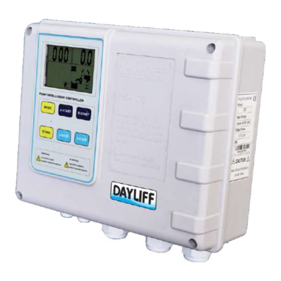
5. OPERATION 5.1 Manual & Auto Mode 5.2 Pump Operation 5.3 Historical Fault Display 5.4 Pump Running Hours Display 5.5 Communication Link and Remote Monitoring 6. Trouble Shooting 7. Terms of Warranty... - Page 5 Area Status Displaying Area Dayliff SmartCon 2 is a high specification multifunction electronic twin-pump controller designed for a wide variety of operating conditions in borehole, wastewater, booster and general water supply applications. Controllers are fitted with a digital display that indicates both operating and fault parameters and can be programmed using panel buttons for various functions.
- Page 6 Dayliff SmartCon 2 is a comprehensive control solution for all pumping requirements in both submersible and surface applications providing exceptional levels of functionality and protection in one compact enclosure. They are the ideal solution for all twin pump installations. OPERATING CONDITIONS Enclosure Class: IP54 Temperature Range: -25°...
- Page 7 3. TECHNICAL SPECIFICATIONS 3.1 Smartcon Components Fig 1: SmartCon Controller Components 1. USB port 5. Passive dry contacting point 2. Control terminals for electrical 6. MCB for electrical connection to connection to float switch/probe the power supply pressure switch 7. Terminals to electrical pump 3.
- Page 8 Icon Meaning/Description Icon Meaning/Description Voltage Second Minute Hour Percentage Ampere (current) Pump running. Pump stops Low/no pressure in the pipeline or High/Full pressure in the pipeline or pressure tank pressure tank Pump parameter configuration-the Time display-pump running hours, count controller is in parameter adjusting down etc manual Pump fault information...
- Page 9 4. INSTALLATION & WIRING All installation and/or maintenance must be done by a qualied electrician in observance of the relevant electrical and safety standards. CAUTION Ensure the power specications for the motor and controller match. CAUTION Before any installation or maintenance operation, the controller must be disconnected from the power supply.
- Page 10 4.1 Installation Environment Requirements Installation of the controller according to the specified environmental conditions is the precondition for ensuring long-term normal and stable operation. Environment Factor Requirements Working Temperature -25 C to +55 C Working Humidity 20% to 90% RH Degree of Protection IP54 Install Position...
- Page 11 To avoid the risk of re, make sure to securely tighten the terminal. CAUTION Never connect the AC power to the Motor (U, V, W / L, N) terminals. CAUTION 4.3 Parameter Calibration and Calibration Clearing Pump calibration is done to set the running voltage and current for protection of the pump.
- Page 12 4.4 Installation of Water level Electrode Probe & Float Switch Wrap the signal cable and down-lead of sensor Fixation cone Signal Cable Down-lead of sensor Upper Level (ON) Upper Installation Probe Stand Lower Probe Com Probe Lower Level (OFF) Fig 7: Water Level Electrode (Probe) Fig 8: Float Switch Installation Installation In event of high risk of electric storms (lightning) or when...
- Page 13 4.6 Function Switch Setting There are four built-in pump applications that can be configured using this controller. Ÿ Pressure Boosting Mode Ÿ Emptying Mode Ÿ Water Transfer Mode Ÿ Sewage Pump with piggyback float switch Mode Pressure Boosting Mode Water Transfer Mode Emptying Mode Sewage Pump with piggy oat switch Mode Fig 10: Various Pump Application Mode...
- Page 14 The function switch which is located on the door of the controller as shown in Fig 11 is used to set various pump application requirements. The controller should be disconnected from the power supply before changing the switch. Once the configuration is complete, switch ON the controller.
- Page 15 4.7 Sensor connections for different function switch settings 4.7.1 Pressure Booster Mode Function Switch Setting LCD Display Fig 13: Pressure Booster Mode Setting and Display Operation Ÿ Suppose the pressure setting of Pressure Switch B is higher than Pressure A. Ÿ...
- Page 16 Fig 15: Pressure Booster Mode with Pressure Switches on Delivery Pipeline and Level Electrodes on Source Tank Low Water Level in Source Tank Delivery Tank Full Low Pressure in Pipeline or Pressure High Pressure in Pipeline or Pressure Tank Tank Fig 16: Meaning of Messages and Graphic on LCD 4 12...
- Page 17 4.7.2 Water Transfer Mode Function switch setting LCD display Fig 17: Water Transfer Mode Setting and Display Operation: Normal Water Demand Fig 18 and 19 When the delivery tank water level is: Ÿ Lower than Probe 1(float switch A: Down level), the controller will only run one pump.
- Page 18 Fig 19: Water Transfer Mode with Delivery Tank Water Level Float Switches Low Water Level in Source Tank Source Tank Full Delivery Tank Full Low Water Level on Delivery Tank Fig 20: Meaning of Messages and Graphic on LCD 4 14...
- Page 19 4.7.3 Emptying Mode Function Switch Setting LCD Display Fig 21: Emptying Mode Setting and Display Operation: Normal liquid level in the sump Fig 22 When the water level reaches Probe 3 (Float Switch A: Up Level), the controller will run a single pump; when the water level declines to Probe 2 (Float Switch A: Down Level), the single pump stops running.
- Page 20 Fig 23: Emptying Mode with Float Switches at Source Tank Auto Patrol (Anti-rust) Function Auto Patrol function is a pump shaft antirust protection that helps protect the drainage / sewage pump from rust and the impeller being jammed due to extended periods of inactivity.
- Page 21 4.7.4 Sewage Pump with piggyback oat switch mode Function switch setting LCD display 1 2 3 Fig 25: Sewage Pump Mode Setting and Display Operation: Ÿ Main pump and standby pump automatically alternate due to water level sensor position When water level raises and float switch A/B rise to up level, controller will run pump A.
-
Page 22: Operation
Overow in Sump Tank Fig 27: Meaning of Messages and Graphic on LCD 5. OPERATION 5.1 MANUAL and AUTO mode Press the key to switch between the Manual and Auto mode. In Manual mode, the operator can run individual pumps by pressing keys and pressing keys to stop individual pumps. -
Page 23: Pump Running Hours Display
NOTE 5.5 Communication Link and Remote Monitoring Smartcon 2 comes with an inbuilt communication interface (Modbus RS485) that can be used to integrate the controller to external Building Management Systems or iDayliff IoT. Please contact Dayliff for more information on the integration. -
Page 24: Trouble Shooting
6. TROUBLE SHOOTING PROBLEM POSSIBLE CAUSE SOLUTION Report low line voltage to the power utility company Flashing The pump motor running voltage is UNDER V lower Controller will attempt to restart the than the calibrated voltage, pump pump every 5 minutes until line voltage is restored to normal Pu m p m o t o r r u n n i n g c u r r e n t Flashing of... - Page 25 PROBLEM POSSIBLE CAUSE SOLUTION Report high line voltage to the power utility company The running voltage is higher than Flashing the calibrated voltage, pump is in Controller will attempt to restart the OVER V over voltage protection state pump every 5 minutes until line voltage is restored to normal Power supply phase loss Report to the power utility company...
-
Page 26: Terms Of Warranty
General Liability • In lieu of any warranty, condition or liability implied by law, the liability of Dayliff (hereafter called the Distributor) in respect of any defect or failure of equipment supplied is limited to making good by replacement or repair (at the Distributor’s discretion) defects which under proper use... - Page 28 www.davisandshirtliff.com INS497A-04/22...