
Related Manuals for Vecow RCS-9430F-GTX1080


Summary of Contents for Vecow RCS-9430F-GTX1080
- Page 1 USER USER RCS-9000F GTX1080 Manual Manual Intel ® Xeon ® /Core™ i7 GPU Computing System with NVIDIA ® GeForce ® GTX1080 Workstation-grade Performance, Expandable, Independent Graphics 1.0.0 Edition 20180402...
- Page 2 Record of Revision Version Date Page Description Remark 0.10 2018/04/10 Preliminary Release 1.00 2018/04/12 Official Release...
-
Page 3: Declaration Of Conformity
This manual is released by Vecow Co., Ltd. for reference purpose only. All product offerings and specifications are subject to change without prior notice. It does not represent commitment of Vecow Co., Ltd. Vecow shall not be liable for direct, indirect, special, incidental, or consequential damages arising out of the use of the product or documentation or any infringements upon the rights of third parties, which may result from such use. - Page 4 Order Information Part Number Description ® ® RCS-9400F, NVIDIA GeForce GTX1080, 2 GigE LAN, RCS-9430F-GTX1080 1 PCIe x4, 1 PCIe x1, 4 COM, 7 USB 3.0, 3 SIM, Isolated DIO ® ® RCS-9400F w/65W CPU, NVIDIA GeForce GTX1080, RCS-9430FH-GTX1080 2 GigE LAN, 1 PCIe x4, 1 PCIe x1, 4 COM, 7 USB 3.0, 3 SIM, Isolated DIO ®...
- Page 5 Order Accessories Part Number Description ® ® E3-1275 v6 Intel Xeon E3-1275 v6 Processor, 8M Cache, up to 4.20 GHz, 73W E3-1275 v5 Intel ® Xeon ® E3-1275 v5 Processor, 8M Cache, up to 4.00 GHz, 80W ® ® E3-1225 v5 Intel Xeon E3-1225 v5 Processor, 8M Cache, up to 3.70 GHz, 80W...
-
Page 6: Table Of Contents
Table of Contents CHAPTER 1 GENERAL INTRODUCTION 1.1 Overview 1.2 Features 1.3 Product Specification 1.3.1 Specifications of RCS-9430F GTX1080 1.3.2 Specifications of RCS-9430FH GTX1080 1.3.3 Specifications of RCS-9430FR GTX1080 1.3.4 Specifications of RCS-9430FHR GTX1080 1.3.5 Specifications of RCS-9421F GTX1080 1.3.6 Specifications of RCS-9421FH 1.3.7 Specifications of RCS-9421FR GTX1080 1.3.8 Specifications of RCS-9421FHR GTX1080 1.3.9 Specifications of RCS-9412F GTX1080... - Page 7 CHAPTER 2 GETTING TO KNOW YOUR RCS-9000F GTX1080 30 2.1 Packing List 2.2 Front Panel I/O & Functions 2.3 Main Board Expansion Connectors 2.4 Main Board Jumper Settings 2.5 Ignition Control CHAPTER 3 SYSTEM SETUP 3.1 How to Open Your RCS-9000F GTX1080 3.2 Installing CPU 3.3 Installing DDR4 SO-DIMM Modules 3.4 Installing Mini PCIe Card...
- Page 8 APPENDIX A : Isolated DIO Guide APPENDIX B : GPIO and WDT Functions APPENDIX C : RAID Installation Guide APPENDIX D : Power Consumption APPENDIX E : Supported Memory & Storage List APPENDIX F : Power Supply Installation viii...
-
Page 9: Chapter 1 General Introduction
Pascal™ architecture and up to 400% GPU computing performance, max 8K resolution and 7 independent HD displays, Vecow RCS-9000F GTX1080 boost up to 49% system performance enhancement and 1637% GPU performance improved than the platform without additional graphics engine; PCIe 3.0 (8GT/s), Multiple SATA III (6Gbps), USB 3.0 (5Gbps), PoE (1Gbps) LAN and wireless connections make high-... -
Page 10: Features
• 7 USB 3.0 (6 External, 1 Internal) • 2 USB 2.0 (Internal) Isolated DIO 32 Isolated DIO (16 DI, 16 DO) Power, HDD, Wireless SIM Card 3 SIM Card Socket (2 External, 1 Internal) ©Vecow RCS-9000F GTX1080 User Manual GENERAL INTRODUCTION... - Page 11 Expansion 3 Mini PCIe Socket : Mini PCIe • 2 Full-size for PCIe/USB/External SIM Card • 1 Full-size for PCIe/USB/Internal SIM Card/mSATA • 1 PCIe x4 Slot PCI/PCIe • 1 PCIe x1 Slot Graphics ® • Intel HD Graphics 630/530 Graphics Processor ®...
- Page 12 • IEC 60068-2-27 Shock • SSD : 50G @ wallmount, Half-sine, 11ms • IEC 60068-2-64 Vibration • SSD : 5Grms, 5Hz to 500Hz, 3 Axis CE, FCC, EN50155, EN50121-3-2 ©Vecow RCS-9000F GTX1080 User Manual GETTING TO KNOW YOUR RCS-9000F GTX1080...
-
Page 13: Specifications Of Rcs-9430Fh Gtx1080
1.3.2 Specifications of RCS-9430FH GTX1080 System ® ® Quad Core Intel Xeon /Core™ i7/i5/i3 Processor (Kaby Processor Lake-S/Skylake-S) ® Chipset Intel C236 BIOS IT8786E • DDR4 2133MHz Memory • Up to 32GB • 2 204-pin SO-DIMM Socket I/O Interface 4 COM RS-232/422/485 with auto flow control Serial (ESD protection : Air gap ±15kV, Contact ±8kV) •... - Page 14 Relative Humidity 95% at 55°C • IEC 60068-2-27 Shock • SSD : 50G @ wallmount, Half-sine, 11ms • IEC 60068-2-64 Vibration • SSD : 5Grms, 5Hz to 500Hz, 3 Axis CE, FCC, EN50155, EN50121-3-2 ©Vecow RCS-9000F GTX1080 User Manual GENERAL INTRODUCTION...
-
Page 15: Specifications Of Rcs-9430Fr Gtx1080
1.3.3 Specifications of RCS-9430FR GTX1080 System ® ® Quad Core Intel Xeon /Core™ i7/i5/i3 Processor Processor (Kaby Lake-S/Skylake-S) Chipset Intel ® C236 BIOS IT8786E • DDR4 2133MHz Memory • Up to 32GB • 2 204-pin SO-DIMM Socket I/O Interface 4 COM RS-232/422/485 with auto flow control Serial (ESD protection : Air gap ±15kV, Contact ±8kV) •... - Page 16 Relative Humidity 95% at 60°C • IEC 60068-2-27 Shock • SSD : 50G @ wallmount, Half-sine, 11ms • IEC 60068-2-64 Vibration • SSD : 5Grms, 5Hz to 500Hz, 3 Axis CE, FCC, EN50155, EN50121-3-2 ©Vecow RCS-9000F GTX1080 User Manual GENERAL INTRODUCTION...
-
Page 17: Specifications Of Rcs-9430Fhr Gtx1080
1.3.4 Specifications of RCS-9430FHR GTX1080 System ® ® Quad Core Intel Xeon /Core™ i7/i5/i3 Processor Processor (Kaby Lake-S/Skylake-S) ® Chipset Intel C236 BIOS IT8786E • DDR4 2133MHz Memory • Up to 32GB • 2 204-pin SO-DIMM Socket I/O Interface 4 COM RS-232/422/485 with auto flow control Serial (ESD protection : Air gap ±15kV, Contact ±8kV) •... - Page 18 Relative Humidity 95% at 55°C • IEC 60068-2-27 Shock • SSD : 50G @ wallmount, Half-sine, 11ms • IEC 60068-2-64 Vibration • SSD : 5Grms, 5Hz to 500Hz, 3 Axis CE, FCC, EN50155, EN50121-3-2 ©Vecow RCS-9000F GTX1080 User Manual GENERAL INTRODUCTION...
-
Page 19: Specifications Of Rcs-9421F Gtx1080
1.3.5 Specifications of RCS-9421F GTX1080 System ® ® Quad Core Intel Xeon /Core™ i7/i5/i3 Processor Processor (Kaby Lake-S/Skylake-S) ® Chipset Intel C236 BIOS IT8786E • DDR4 2133MHz Memory • Up to 32GB • 2 204-pin SO-DIMM Socket I/O Interface 4 COM RS-232/422/485 with auto flow control Serial (ESD protection : Air gap ±15kV, Contact ±8kV) •... - Page 20 Relative Humidity 95% at 60°C • IEC 60068-2-27 Shock • SSD : 50G @ wallmount, Half-sine, 11ms • IEC 60068-2-64 Vibration • SSD : 5Grms, 5Hz to 500Hz, 3 Axis CE, FCC, EN50155, EN50121-3-2 ©Vecow RCS-9000F GTX1080 User Manual GENERAL INTRODUCTION...
-
Page 21: Specifications Of Rcs-9421Fh
1.3.6 Specifications of RCS-9421FH System ® ® Quad Core Intel Xeon /Core™ i7/i5/i3 Processor Processor (Kaby Lake-S/Skylake-S) ® Chipset Intel C236 BIOS IT8786E • DDR4 2133MHz Memory • Up to 32GB • 2 204-pin SO-DIMM Socket I/O Interface 4 COM RS-232/422/485 with auto flow control Serial (ESD protection : Air gap ±15kV, Contact ±8kV) •... - Page 22 Relative Humidity 95% at 55°C • IEC 60068-2-27 Shock • SSD : 50G @ wallmount, Half-sine, 11ms • IEC 60068-2-64 Vibration • SSD : 5Grms, 5Hz to 500Hz, 3 Axis CE, FCC, EN50155, EN50121-3-2 ©Vecow RCS-9000F GTX1080 User Manual GENERAL INTRODUCTION...
-
Page 23: Specifications Of Rcs-9421Fr Gtx1080
1.3.7 Specifications of RCS-9421FR GTX1080 System ® ® Quad Core Intel Xeon /Core™ i7/i5/i3 Processor Processor (Kaby Lake-S/Skylake-S) ® Chipset Intel C236 BIOS IT8786E • DDR4 2133MHz Memory • Up to 32GB • 2 204-pin SO-DIMM Socket I/O Interface 4 COM RS-232/422/485 with auto flow control Serial (ESD protection : Air gap ±15kV, Contact ±8kV) •... - Page 24 Relative Humidity 95% at 60°C • IEC 60068-2-27 Shock • SSD : 50G @ wallmount, Half-sine, 11ms • IEC 60068-2-64 Vibration • SSD : 5Grms, 5Hz to 500Hz, 3 Axis CE, FCC, EN50155, EN50121-3-2 ©Vecow RCS-9000F GTX1080 User Manual GENERAL INTRODUCTION...
-
Page 25: Specifications Of Rcs-9421Fhr Gtx1080
1.3.8 Specifications of RCS-9421FHR GTX1080 System ® ® Quad Core Intel Xeon /Core™ i7/i5/i3 Processor Processor (Kaby Lake-S/Skylake-S) ® Chipset Intel C236 BIOS IT8786E • DDR4 2133MHz Memory • Up to 32GB • 2 204-pin SO-DIMM Socket I/O Interface 4 COM RS-232/422/485 with auto flow control Serial (ESD protection : Air gap ±15kV, Contact ±8kV) •... - Page 26 Relative Humidity 95% at 55°C • IEC 60068-2-27 Shock • SSD : 50G @ wallmount, Half-sine, 11ms • IEC 60068-2-64 Vibration • SSD : 5Grms, 5Hz to 500Hz, 3 Axis CE, FCC, EN50155, EN50121-3-2 ©Vecow RCS-9000F GTX1080 User Manual GENERAL INTRODUCTION...
-
Page 27: Specifications Of Rcs-9412F Gtx1080
1.3.9 Specifications of RCS-9412F GTX1080 System ® ® Quad Core Intel Xeon /Core™ i7/i5/i3 Processor Processor (Kaby Lake-S/Skylake-S) ® Chipset Intel C236 BIOS IT8786E • DDR4 2133MHz Memory • Up to 32GB • 2 204-pin SO-DIMM Socket I/O Interface 4 COM RS-232/422/485 with auto flow control Serial (ESD protection : Air gap ±15kV, Contact ±8kV) •... - Page 28 Relative Humidity 95% at 60°C • IEC 60068-2-27 Shock • SSD : 50G @ wallmount, Half-sine, 11ms • IEC 60068-2-64 Vibration • SSD : 5Grms, 5Hz to 500Hz, 3 Axis CE, FCC, EN50155, EN50121-3-2 ©Vecow RCS-9000F GTX1080 User Manual GENERAL INTRODUCTION...
-
Page 29: Specifications Of Rcs-9412Fh Gtx1080
1.3.10 Specifications of RCS-9412FH GTX1080 System ® ® Quad Core Intel Xeon /Core™ i7/i5/i3 Processor Processor (Kaby Lake-S/Skylake-S) ® Chipset Intel C236 BIOS IT8786E • DDR4 2133MHz Memory • Up to 32GB • 2 204-pin SO-DIMM Socket I/O Interface 4 COM RS-232/422/485 with auto flow control Serial (ESD protection : Air gap ±15kV, Contact ±8kV) •... - Page 30 Relative Humidity 95% at 55°C • IEC 60068-2-27 Shock • SSD : 50G @ wallmount, Half-sine, 11ms • IEC 60068-2-64 Vibration • SSD : 5Grms, 5Hz to 500Hz, 3 Axis CE, FCC, EN50155, EN50121-3-2 ©Vecow RCS-9000F GTX1080 User Manual GENERAL INTRODUCTION...
-
Page 31: Specifications Of Rcs-9412Fr Gtx1080
1.3.11 Specifications of RCS-9412FR GTX1080 System ® ® Quad Core Intel Xeon /Core™ i7/i5/i3 Processor Processor (Kaby Lake-S/Skylake-S) ® Chipset Intel C236 BIOS IT8786E • DDR4 2133MHz Memory • Up to 32GB • 2 204-pin SO-DIMM Socket I/O Interface 4 COM RS-232/422/485 with auto flow control Serial (ESD protection : Air gap ±15kV, Contact ±8kV) •... - Page 32 Relative Humidity 95% at 60°C • IEC 60068-2-27 Shock • SSD : 50G @ wallmount, Half-sine, 11ms • IEC 60068-2-64 Vibration • SSD : 5Grms, 5Hz to 500Hz, 3 Axis CE, FCC, EN50155, EN50121-3-2 ©Vecow RCS-9000F GTX1080 User Manual GENERAL INTRODUCTION...
-
Page 33: Specifications Of Rcs-9412Fhr Gtx1080
1.3.12 Specifications of RCS-9412FHR GTX1080 System ® ® Quad Core Intel Xeon /Core™ i7/i5/i3 Processor Processor (Kaby Lake-S/Skylake-S) ® Chipset Intel C236 BIOS IT8786E • DDR4 2133MHz Memory • Up to 32GB • 2 204-pin SO-DIMM Socket I/O Interface 4 COM RS-232/422/485 with auto flow control Serial (ESD protection : Air gap ±15kV, Contact ±8kV) •... - Page 34 Relative Humidity 95% at 55°C • IEC 60068-2-27 Shock • SSD : 50G @ wallmount, Half-sine, 11ms • IEC 60068-2-64 Vibration • SSD : 5Grms, 5Hz to 500Hz, 3 Axis CE, FCC, EN50155, EN50121-3-2 ©Vecow RCS-9000F GTX1080 User Manual GENERAL INTRODUCTION...
-
Page 35: Supported Cpu List
1.4 Supported CPU List Processor No. Cache Max. Frequency Embedded ® Xeon E3-1275 v6 Up to 4.20 GHz ® Xeon E3-1275 v5 Up to 4.00 GHz ® Xeon E3-1225 v5 Up to 3.70 GHz ® Xeon E3-1225L v5 Up to 3.40 GHz Core™... -
Page 36: Mechanical Dimension
362.0 (14.25") 330.0 (12.99") 210.0 (8.27") 250.4 (9.86") Unit : mm (inch) 1.5.2 Dimensions of RCS-9430FH GTX1080/RCS-9421FH GTX1080/ RCS-9412FH GTX1080 382.0 (15.04") 362.0 (14.25") 330.0 (12.99") 210.0 (8.27") 250.4 (9.86") Unit : mm (inch) ©Vecow RCS-9000F GTX1080 User Manual GENERAL INTRODUCTION... -
Page 37: Dimensions Of Rcs-9430Fr Gtx1080/Rcs-9421Fr Gtx1080/ Rcs-9412Fr Gtx1080
1.5.3 Dimensions of RCS-9430FR GTX1080/RCS-9421FR GTX1080/ RCS-9412FR GTX1080 382.0 (15.04") 362.0 (14.25") 330.0 (12.99") 210.0 (8.27") 250.4 (9.86") Unit : mm (inch) 1.5.4 Dimensions of RCS-9430FHR GTX1080/RCS-9421FHR GTX1080/ RCS-9412FHR GTX1080 382.0 (15.04") 362.0 (14.25") 330.0 (12.99") 210.0 (8.27") 250.4 (9.86") Unit : mm (inch) GENERAL INTRODUCTION... -
Page 38: Chapter 2 Getting To Know Your Rcs-9000F Gtx1080
RCS-9000F GTX1080 series may contain SSD/HDD and DDR4 SO-DIMM. Please verify these items if necessary.) RCS-9400F Series Accessory box, which contains • Vecow Drivers & Utilities DVD • Wall-mounting bracket • F#6-32x6 screw for wall-mounting bracket • PH-M2.5x6 screw for Mini PCIe Slot •... -
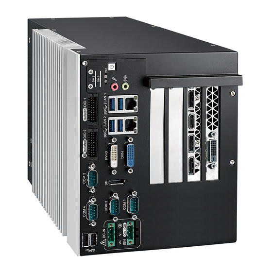
Page 39: Front Panel I/O & Functions
2.2 Front Panel I/O & Functions In Vecow's RCS-9000 series family, all I/O connectors are located on the front panel. Most of the general connections to the computer device, such as audio, USB, DVI-I, DVI-D, DisplayPort, and any additional storage, are placed on the front panel. - Page 40 This connector can output DVI signals. The DVI output mode supports up to 1920x1200 resolution. The DVI mode is automatically selected according to the display device connected. You will need a DVI cable when connecting to a display device. ©Vecow RCS-9000F GTX1080 User Manual GETTING TO KNOW YOUR RCS-9000F GTX1080...
- Page 41 2.2.4 PWR & HDD LED Indicator COM 4 COM 3 Isolated DIO 2 Isolated DIO 1 SIM 2 SIM 3 DC-IN | LAN 2 | LAN 1 DVI-D COM 1 DVI-I On | Off COM 2 Yellow-HDD LED : A hard disk/CFast LED. If the LED is on, it indicates that the system's storage is functional.
- Page 42 RCS-9000. It is also compliant with the requirements of super speed (SS), high speed (HS), full speed (FS), and low speed (LS). ©Vecow RCS-9000F GTX1080 User Manual GETTING TO KNOW YOUR RCS-9000F GTX1080...
- Page 43 2.2.8 SIM 1, SIM 2, SIM 3 COM 4 COM 3 Isolated DIO 2 Isolated DIO 1 SIM 2 SIM 3 DC-IN | LAN 2 | LAN 1 DVI-D COM 1 DVI-I On | Off COM 2 MPCIE1 MPCIE2 CN14 (SIM 1) MPCIE3 Mini PCIe...
- Page 44 1000Mbps Ethernet network; The left LED will keep twinkling/off when Ethernet data packets are being transmitted/received. LED Color 10Mbps 100Mbps 1000Mbps Location Green/ Solid Solid Right Orange Green Orange Blinking Blinking Blinking Left Yellow Yellow Yellow Yellow ©Vecow RCS-9000F GTX1080 User Manual GETTING TO KNOW YOUR RCS-9000F GTX1080...
-
Page 45: Audio Connector
2.2.10 Audio Connector COM 4 COM 3 Isolated DIO 2 Isolated DIO 1 SIM 2 SIM 3 DC-IN | LAN 2 | LAN 1 DVI-D COM 1 DVI-I On | Off COM 2 There are two audio connectors, mic-in and line-out, on the front side of RCS- 9000. Onboard Realtek ALC892 audio codec supports 5.1 channel HD audio and ®... - Page 46 You could turn on or off the system power by using this contact. This terminal block supports dual function on soft power-on/power-off (instant off or delay four seconds), and suspend mode. Pin No. Definition Pin No. Definition IGNITION ©Vecow RCS-9000F GTX1080 User Manual GETTING TO KNOW YOUR RCS-9000F GTX1080...
- Page 47 2.2.14 Isolated DIO COM 4 COM 3 Isolated DIO 2 Isolated DIO 1 SIM 2 SIM 3 DC-IN | LAN 2 | LAN 1 DVI-D COM 1 DVI-I On | Off COM 2 There is a 16-bit DIO (8-bit DI, 8-bit DO) connector in the Isolated rear side.
- Page 48 GPI SOURCE Mode Digital GPI input signal circuit in SOURCE mode (PNP) is illustrated as follows : GPO SINK Mode Digital GPO output circuit in SINK mode (NPN) is illustrated as follows : ©Vecow RCS-9000F GTX1080 User Manual GETTING TO KNOW YOUR RCS-9000F GTX1080...
- Page 49 2.2.15 Serial Port COM COM 4 COM 3 Isolated DIO 2 Isolated DIO 1 SIM 2 SIM 3 DC-IN | LAN 2 | LAN 1 DVI-D COM 1 DVI-I On | Off COM 2 Serial port can be configured for RS-232, RS-422, or RS-485 with auto flow control communication.
-
Page 50: Main Board Expansion Connectors
SATA1 CN20 BAT1 CN36 SATA3 SATA4 FAN1 CN15 FAN2 MPCIE1 JUSB1 mSATA BIOS MPCIE2 CN39 MPCIE3 2.3.2 Rear View of RCS-9000 Main Board With Connector Location Skylake-S C236 CN16 ©Vecow RCS-9000F GTX1080 User Manual GETTING TO KNOW YOUR RCS-9000F GTX1080... - Page 51 2.3.3 CN12 : GPIO CN12 The RCS-9000 offers sixteen programmable I/O within TTL 5V tolerance. If the GPIO is logic high, it indicates that the mapping on SIO GPIO pin is logic high level. If the GPIO is logic low, it indicates that the mapping on SIO GPIO pin is logic low level.
- Page 52 Panasonic BR2032 190mAh lithium battery. It is recommended that you do not replace the lithium battery on your own. If the battery needs to be changed, please contact the Vecow RMA service team. ©Vecow RCS-9000F GTX1080 User Manual GETTING TO KNOW YOUR RCS-9000F GTX1080...
- Page 53 2.3.6 CN8 : One PCIe x4 or Four PCIe x1 (PCH) The pin assignments of CN8 are listed in the following table : Pin No. Function Pin No. Function Reserved +V12S +V12S +V12S +V12S +V12S CLKOUT_100M_X4_P9 SM_SLOT_CLK CLKOUT_100M_X4_N9 SM_SLOT_DAT CLKOUT_100M_X4_P10 CLKOUT_100M_X4_N10 +V3.3S +V3.3S Reserved...
- Page 54 PLTRST_PCIE# WAKE# Reserved CLKOUT_100M_X16_P4 CLKOUT_100M_X16_N4 PEG_TXP_0 PEG_TXN_0 PEG_RXP_0 PEG_RXN_0 Reserved Reserved PEG_TXP_1 PEG_TXN_1 PEG_RXP_1 PEG_RXN_1 PEG_TXP_2 PEG_TXN_2 PEG_RXP_2 PEG_RXN_2 PEG_TXP_3 PEG_TXN_3 PEG_RXP_3 PEG_RXN_3 PCIE_RXP19 PCIE_RXN19 CLKOUT_100M_X16_P3 CLKOUT_100M_X16_N3 PEG_TXP_4 PEG_TXN_4 ©Vecow RCS-9000F GTX1080 User Manual GETTING TO KNOW YOUR RCS-9000F GTX1080...
- Page 55 Pin No. Function Pin No. Function PEG_RXP_4 PEG_RXN_4 PEG_TXP_5 PEG_TXN_5 PEG_RXP_5 PEG_RXN_5 PEG_TXP_6 PEG_TXN_6 PEG_RXP_6 PEG_RXN_6 PEG_TXP_7 PEG_TXN_7 PEG_RXP_7 PEG_RXN_7 Reserved Reserved PEG_TXP_8 PEG_TXN_8 PEG_RXP_8 PEG_RXN_8 PEG_TXP_9 PEG_TXN_9 PEG_RXP_9 PEG_RXN_9 PEG_TXP_10 PEG_TXN_10 PEG_RXP_10 PEG_RXN_10 PEG_TXP_11 PEG_TXN_11 PEG_RXP_11 PEG_RXN_11 PEG_TXP_12 PEG_TXN_12 PEG_RXP_12 PEG_RXN_12 PEG_TXP_13...
- Page 56 Pin No. Definition Pin No. Definition 2.3.9 J1 : LPC Port 80 Debug Port Pin No. Definition Pin No. Definition +V3.3S LPC_AD3 LPC_SERIRQ LPC_FRAME# LPC_AD0 CLK_LPC_80 LPC_AD1 BUF_PLTRST_N_B LPC_AD2 ©Vecow RCS-9000F GTX1080 User Manual GETTING TO KNOW YOUR RCS-9000F GTX1080...
- Page 57 2.3.10 CN20, CN36 : SATA Power Connector CN20 CN36 The RCS-9000 is also equipped with two SATA power connectors. It supports 5V (Up to 3A) and 12V (Up to 3A) currents to the hard drive or SSD. The pin assignments of CN20 and CN36 are listed in the following table : Pin No.
- Page 58 1x10-pin connector on one end and a USB connector on the other. The pin assignments of JUSB1 are listed in the following table : Pin No. Definition Pin No. Definition USB2_H1_PWR USB_D_9N USB2_H1_PWR USB_D_9P USB2_H1_PWR USB_D_7N USB_D_7P ©Vecow RCS-9000F GTX1080 User Manual GETTING TO KNOW YOUR RCS-9000F GTX1080...
- Page 59 2.3.13 MPCIE1 : Mini PCIe, mSATA MPCIE1 mSATA Both mSATA and mini PCIe share the same form factor and similar electrical pinout assignments on their connectors. There was no clear mechanism to distinguish if an mSATA drive or a Mini PCIe device is plugged into the socket until recently that SATA I/O issued an ECN change (ECN #045) to redefine pin- 43 on mSATA connector as "no connect"...
- Page 60 USB_D+ USB_D- PETp0 PETn0 SMB_DATA SMB_CLK +1.5V PERp0 PERn0 +3.3Vaux PERST# Reserved reserved Reserved Mechanical Key Reserved REFCLK+ Reserved REFCLK- Reserved Reserved CLKREQ# Reserved Reserved 1.5V Reserved WAKE# 3.3Vaux ©Vecow RCS-9000F GTX1080 User Manual GETTING TO KNOW YOUR RCS-9000F GTX1080...
- Page 61 2.3.14 MPCIE2, MPCIE3 : Mini PCIe MPCIE2 MPCIE3 The pin assignments of MPCIE2 and MPCIE3 are listed in the following table : Pin No. function Pin No. function Reserved +3.3Vaux Reserved Reserved +1.5V Reserved Reserved Reserved +3.3Vaux Reserved +3.3Vaux GETTING TO KNOW YOUR RCS-9000F GTX1080...
- Page 62 USB_D+ USB_D- PETp0 PETn0 SMB_DATA SMB_CLK +1.5V PERp0 PERn0 +3.3Vaux PERST# Reserved reserved Reserved Mechanical Key Reserved REFCLK+ Reserved REFCLK- Reserved Reserved CLKREQ# Reserved Reserved 1.5V Reserved WAKE# 3.3Vaux ©Vecow RCS-9000F GTX1080 User Manual GETTING TO KNOW YOUR RCS-9000F GTX1080...
- Page 63 2.3.15 CN9 : CFast The RCS-9000 system comes with a CFast socket on the front panel for Type-I/ Type-II compact flash card. It is implemented by a SATA III Port from C236 PCH. Be sure to disconnect the power source and unscrew the CFast socket cover before installing a CFast card.
- Page 64 DIO2_GPI5 SIO_GPI86 DIO2_GPI6 SIO_GPI87 DIO2_GPI7 SIO_GPO70 DIO2_GPO0 SIO_GPO71 DIO2_GPO1 SIO_GPO72 DIO2_GPO2 SIO_GPO73 DIO2_GPO3 SIO_GPO74 DIO2_GPO4 SIO_GPO75 DIO2_GPO5 SIO_GPO76 DIO2_GPO6 SIO_GPO77 DIO2_GPO7 UART3_DCD# UART4_DCD# UART3_RXD UART4_RXD UART3_TXD UART4_TXD UART3_DTR# UART4_DTR# ©Vecow RCS-9000F GTX1080 User Manual GETTING TO KNOW YOUR RCS-9000F GTX1080...
- Page 65 UART3_DSR# UART4_DSR# UART3_RTS# UART4_RTS# UART3_CTS# UART4_CTS# UART3_RI# UART4_RI# UART3_MODE0 UART4_MODE0 UART3_MODE1 UART4_MODE1 UART3_MODE2 UART4_MODE2 SP338E_TERM_COM3 SP338E_TERM_COM4 +V3.3S +V3.3S +V3.3S +V3.3S PCIE_TXP20 PCIE_RXP20 PCIE_TXN20 PCIE_RXN20 USB3_P10_RX_DN USB3_P8_RX_DN USB3_P10_RX_DP USB3_P8_RX_DP USB3_P10_TX_DN USB3_P8_TX_DN USB3_P10_TX_DP USB3_P8_TX_DP USB_P10_DP USB_P8_DP USB_P10_DN USB_P8_DN +V5A +V5A +V5A +V5A 2.3.17 CN39 : 6pin Power Connector CN39 Pin No.
-
Page 66: Main Board Jumper Settings
2 or 2 and 3. The figure below is the top view of the RCS-9000 main board. It shows the location of the jumpers. Closed Closed 2-3 2.4.1 Front View of RCS-9000 Main Board With Jumper Location ©Vecow RCS-9000F GTX1080 User Manual GETTING TO KNOW YOUR RCS-9000F GTX1080... - Page 67 2.4.2 JP4, JP5 Pin Header Pin No. Description +5V (1A max.) COM1 +12V (0.5A max.) RI (Default) Pin Header Pin No. Description +5V (1A max.) COM2 +12V (0.5A max.) RI (Default) GETTING TO KNOW YOUR RCS-9000F GTX1080...
- Page 68 PCIe Configuration (3-5) (4-6) 1 x 8, 2 x 4 (3-5) (2-4) 2 x 8 (1-3) (2-4) 1 x16 2.4.4 JP2 : Clear CMOS Pin Header Pin No. Description Normal (Default) Clear CMOS ©Vecow RCS-9000F GTX1080 User Manual GETTING TO KNOW YOUR RCS-9000F GTX1080...
- Page 69 2.4.5 JP6 : USB Wake Up Pin Header Pin No. Definition USB 3.0 and USB 2.0 Wake Up Disable USB 3.0 and USB 2.0 Wake Up Enable (Default) 2.4.6 JP3 Pin Header Pin No. Definition Disable Flash Descriptor Security (override) Enable security measures defined in the Flash Descriptor.
-
Page 70: Ignition Control
The RCS-9000 series provide ignition power control feature for in-vehicle applications. The built-in MCU monitors the ignition signal and turns on/off the system according to pre-defined on/off delay period. ©Vecow RCS-9000F GTX1080 User Manual GETTING TO KNOW YOUR RCS-9000F GTX1080... - Page 71 2.5.2 Adjust Ignition Control Modes The RCS-9000 series provide sixteen modes of different power on/off delay periods adjustable via rotary switch. The default rotary switch is set to 0 in ATX/ AT power mode. The modes are listed in the following table : DIP-Switch Power on delay Power off delay...
- Page 72 3. For proper ignition control, the power button setting should be "Power down" mode. In Windows, for example, you need to set "When I press the power button" to "Shut down." ©Vecow RCS-9000F GTX1080 User Manual GETTING TO KNOW YOUR RCS-9000F GTX1080...
-
Page 73: Chapter 3 System Setup
SYSTEM SETUP 3.1 How to Open Your RCS-9000F GTX1080 Step 1 Remove two F-6-32x6 screws (circled in red) and five F-M3x4 screws (circled in yellow) on the top cover. Take off the top cover HARDWARE INSTALLATION... - Page 74 Step 2 Remove ATX power cable on MB and GTX-1080. Take off the top cover. ©Vecow RCS-9000F GTX1080 User Manual HARDWARE INSTALLATION...
- Page 75 Step 3 Remove two M3x5L screws. Push down the PCIe x16 slot lock and remove GTX-1080. HARDWARE INSTALLATION...
- Page 76 Step 4 Remove five F-M3x4 screws on the bottom cover. Remove two F-M3x4 screws on the front. ©Vecow RCS-9000F GTX1080 User Manual HARDWARE INSTALLATION...
- Page 77 Remove three F-M3x4 screws on the rear. Take off the bottom cover. HARDWARE INSTALLATION...
- Page 78 Step 5 Remove riser card PH-M3 screws (circle in red), FAN cable (circle in yellow) and take off the riser card. ©Vecow RCS-9000F GTX1080 User Manual HARDWARE INSTALLATION...
- Page 79 Step 6 Remove com ports eight #4-40 (red) and one KHS-632x8 (yellow) screw on the front panel. Remove four F-632x6 screws. HARDWARE INSTALLATION...
- Page 80 Step 7 Take off the front panel sequence 1~3. Sequence 1. ©Vecow RCS-9000F GTX1080 User Manual HARDWARE INSTALLATION...
- Page 81 Sequence 2. Sequence 3. HARDWARE INSTALLATION...
- Page 82 Step 8 Take off the SATA cable. ©Vecow RCS-9000F GTX1080 User Manual HARDWARE INSTALLATION...
-
Page 83: Installing Cpu
3.2 Installing CPU Step 1 Remove five M3x11 Spring screws (red) and five PH M3x6L screws (yellow). Step 2 Open the CPU slot. Step 3 Push the slot key. HARDWARE INSTALLATION... - Page 84 Step 4 Check CPU and CPU slot Step 5 Close the slot key. lock pin. Step 6 Make sure the key is in the screw. ©Vecow RCS-9000F GTX1080 User Manual HARDWARE INSTALLATION...
-
Page 85: Installing Ddr4 So-Dimm Modules
3.3 Installing DDR4 SO-DIMM Modules Step 1 Install DDR4 RAM module into SO-DIMM slot. Step 2 Make sure the RAM module is locked by the memory slot (red). HARDWARE INSTALLATION... -
Page 86: Installing Mini Pcie Card
3.4 Installing Mini PCIe Card Step 1 Install Mini PCIe card into the Mini PCIe slot. Step 2 Fasten one M2.5 screw. ©Vecow RCS-9000F GTX1080 User Manual HARDWARE INSTALLATION... -
Page 87: Installing Antenna Cable
3.5 Installing Antenna Cable Step 1 Check antenna cable and washers. Step 2 Remove one rubber cork from the rear panel. (pick the location you want). HARDWARE INSTALLATION... - Page 88 Step 3 Fasten washer 1, washer 2, and washer 3 on Antenna cable connector. Step 4 Antenna cable installation is finished. ©Vecow RCS-9000F GTX1080 User Manual HARDWARE INSTALLATION...
-
Page 89: Installing Cfast Card
3.6 Installing CFast Card Step 1 Open the top cover so you can see the CFast slot. Step 2 Install the CFast card in the slot. HARDWARE INSTALLATION... -
Page 90: Installing Sim Card
3.7 Installing SIM Card 3.7.1 External SIM Card Step 1 Remove SIM cover. Step 2 Install SIM card in the Step 3 Finish. marked red area. ©Vecow RCS-9000F GTX1080 User Manual HARDWARE INSTALLATION... - Page 91 3.7.2 Internal SIM Card Step 1 Open the top cover so you can see the SIM slot. Step 2 Finish. HARDWARE INSTALLATION...
-
Page 92: Installing Pci/Pcie Card
Step 1 Open the top cover so you Step 2 Remove M3x5L screws can see the PCI/PCle slot. and PCI bracket. Step 3 Install the PCI/PCIe Card Step 4 Finish. and lock it in place. ©Vecow RCS-9000F GTX1080 User Manual HARDWARE INSTALLATION... -
Page 93: Installing Ssd/Hdd
3.9 Installing SSD/HDD 3.9.1 External SSD/HDD (For RCS-9430FR/9430FHR/9421FR/9421FHR/ 9412FR/9412FHR-GTX1080) Step 1 Trigger and open SSD/ Step 2 Insert 2.5" SSD/HDD into HDD tray. the tray. SATA 4 SATA 3 SATA 2 SATA 1 Step 3 Push back and close the Step 4 Lock the SSD/HDD tray SSD/HDD tray. - Page 94 3.9.2 Internal SSD/HDD (For RCS-9430F/9430FH/9421F/9421FH/ 9412F/9412FH-GTX1080) Step 1 Repeat 3.1 steps one through seven. Step 2 Remove four F-M3x4 screws (red). ©Vecow RCS-9000F GTX1080 User Manual HARDWARE INSTALLATION...
- Page 95 Step 3 Install SSD/HDD with bracket. Loch the SSD/HDD with bracket in F-M3x4L (one SSD with four F-M3x4L). HARDWARE INSTALLATION...
-
Page 96: Mounting Your Rcs-9000F Gtx1080
3.10 Mounting Your RCS-9000F GTX1080 Step 1 Take the RCS-9000 wallmount. Step 2 Install wall mount to Step 3 Install four F-632x6L RCS-9000 bottom. screws. ©Vecow RCS-9000F GTX1080 User Manual HARDWARE INSTALLATION... -
Page 97: Chapter 4 Bios And Driver Setting
BIOS AND DRIVER SETTING 4.1 BIOS Settings BIOS provides an interface for users to check and change system configuration. The BIOS setup program is accessed by pressing the <Del> key when POST display output is shown. Figure 4-1 : Entering Setup Screen BIOS AND DRIVER SETTING... -
Page 98: Main Menu
Set the time. Use <Tab> to switch between time elements. 4.3 Advanced Function Select advanced tab to enter advanced BIOS setup options, such as CPU configuration, SATA configuration, and USB configuration. Figure 4-3 : BIOS Advanced Menu ©Vecow RCS-9000F GTX1080 User Manual BIOS AND DRIVER SETTING... - Page 99 4.3.1 CPU Configuration Figure 4-3-1 : CPU Configuration Hardware Prefetcher To turn on/off the MLC streamer prefetcher. Adjacent Cache Line Prefetch To turn on/off prefetching of adjacent cache lines. Intel (VMX) Virtualization Technology When enabled, a VMM can utilize the additional hardware capabilities provided by Vanderpool Technology.
- Page 100 Enable or disable CPU C states. Enhanced C-states Enable/disable C1E. When enabled, CPU will switch to minimum speed when all cores enter C-State. Thermal Save Mode Enable/Disable Thermal Save Mode support. ©Vecow RCS-9000F GTX1080 User Manual BIOS AND DRIVER SETTING...
- Page 101 4.3.2.2 GT – Power Management Control Figure 4-3-2-2 : GT – Power Management Control RC6 (Render Standby) Check to enable render standby support. Maximum GT frequency Maximum GT frequency limited by the user. Choose between 350MHz (RPN) and 1150MHz (RP0). Value beyond the range will be clopped to min/max supported by SKU 4.3.3 PCH-FW Configuration Figure 4-3-3 : PCH-FW Settings...
-
Page 102: Trusted Computing
S3 Video Repost Enables or disables S3 video repost. 4.3.6 SMART Settings Figure 4-3-6 : SMART Settings SMART Self Test Run SMART self test on all HDDs during POST. ©Vecow RCS-9000F GTX1080 User Manual BIOS AND DRIVER SETTING... -
Page 103: Hardware Monitor
4.3.7 IT8786 Super IO Configuration Figure 4-3-7 : IT8786 Super IO Configuration 4.3.7.1 Serial Port X Configuration Figure 4-3-7-1 : Serial Port X Configuration Serial Port 1 to port 4 Configuration Options for Serial Port 1 to Serial Port 4. Entering the corresponding Port option then end user can change the settings such as I/O resource and UART mode (High Speed Serial Port is Port 1 only). -
Page 104: Serial Port Console Redirection
These settings specify how the host computer and the remote computer (which the user is using) will exchange data. Both computers should have the same or compatible settings. 4.3.10 Intel TXT Information Display Intel TXT information. Figure 4-3-10 : Intel TXT Information ©Vecow RCS-9000F GTX1080 User Manual BIOS AND DRIVER SETTING... -
Page 105: Pci Subsystem Setting
4.3.11 Acoustic Management Configuration Figure 4-3-11 : Acoustic Management Settings Acoustic Management Configuration Option to enable or disable automatic acoustic management. 4.3.12 PCI Subsystem Setting Figure 4-3-12 : PCI Subsystem Settings Above 4G Decoding Globally Enables or Disables 64bit capable Devices to be Decoded in Above 4G Address Space (Only if System Supports bot PCI Decoding) 4.3.13 Network Stack Configuration Figure 4-3-13 : Network Stack Configuration... - Page 106 PXE boot wait time Wait time to press ESC key to abort the PXE boot. Media detect count Number of times presence of media will be checked. 4.3.14 CSM Configuration Figure 4-3-14 : CSM Settings ©Vecow RCS-9000F GTX1080 User Manual BIOS AND DRIVER SETTING...
- Page 107 CSM Support Enable/disable CSM support. GateA20 Active UPON REQUEST-GA20 can be disabled using BIOS services. ALWAYS - do not allow GA20 to be disabled; this option is useful when any RT code is executed above 1MB. Option ROM Messages Set display mode for option ROM. INT19 Trap Response BIOS reaction on INT19 trapping by Option ROM: IMMEDIATE - execute the trap right away;...
- Page 108 Maximum time the device will take before it properly reports itself to the host controller. 'Auto' uses default value: for a root port it is 100ms, for a hub port the delay is taken from hub descriptor. ©Vecow RCS-9000F GTX1080 User Manual BIOS AND DRIVER SETTING...
-
Page 109: Chipset Functions
4.4 Chipset Functions Figure 4-4 : BIOS Chipset Menu System Agent (SA) Configuration System Agent (SA) parameters. PCH-IO Configuration PCH parameters. GPIOManager Configuration GPIOManager parameters. 4.4.1 System Agent (SA) Configuration Figure 4-4-1 : System Agent Settings VT-d VT-d capability. GMM Device (B0:D8:F0) Enable/disable SA GMM device. -
Page 110: Memory Configuration
Select which of IGFX/PEG/PCI Graphics device should be Primary Display Or select SG for Switchable Gfx. Internal graphics Keep IGFX enabled based on the setup options. GTT Size Select the GTT Size. ©Vecow RCS-9000F GTX1080 User Manual BIOS AND DRIVER SETTING... - Page 111 Aperture Size Select the Aperture Size. Note: Above 4GB MMIO BIOS assignment is automatically enabled when selecting 2048MB aperture. To use this feature, please disable CSM Support. DVMT Pre-Allocated Select DVMT 5.0 Pre-Allocated (Fixed) Graphics Memory size used by the Internal Graphics Device.
- Page 112 Bios options for PCIe device on Intel Ethernet Controller I210 LAN. miniPCIe Slot 1~3 Bios options for PCIe devices on miniPCIe Slot. PCI Express x4 Slot Bios options for PCIe device on PCI Express x4 Slot. ©Vecow RCS-9000F GTX1080 User Manual BIOS AND DRIVER SETTING...
- Page 113 4.4.2.2 SATA and RST Configuration Figure 4-4-2-2 : SATA And RST Settings SATA Controller(s) Enable or disable SATA Device. SATA Mode Selection Determines how SATA controller(s) operate. Software Feature Mask Configuration RAID OROM/RST driver will refer to the SWFM configuration to enable or disable the storage features.
-
Page 114: Security
Identify the SATA Topology if it is Default or ISATA or Flex or DirectConnect or M2. 4.5 Security Figure 4-5 : BIOS Security Menu Administrator Password Set administrator password. User Password Set user password. Secure Boot Customizable Secure Boot Settings. ©Vecow RCS-9000F GTX1080 User Manual BIOS AND DRIVER SETTING... - Page 115 4.5.1 HDD Security Configuration Figure 4-5-1 : HDD Security Settings Set User Password Set HDD user password. *** Advisable to power cycle system after setting hard disk passwords *** Discard or save changes option in setup does not have any impact on HDD when password is set or removed.
-
Page 116: Boot
Sets the system boot order. New Boot Option Policy Controls the placement of newly detected UEFI boot options. Hard Drive BBS Priorities Set the order of the Legacy devices in this group. ©Vecow RCS-9000F GTX1080 User Manual BIOS AND DRIVER SETTING... -
Page 117: Save & Exit
4.7 Save & Exit Figure 4-7 : Bios Save and Exit Menu Save Changes and Exit Exit system setup after saving the changes. Discard Changes and Exit Exit system setup without saving any changes. Save Changes and Reset Reset the system after saving the changes. Discard Changes and Reset Reset system setup without saving any changes. -
Page 118: Appendix A : Isolated Dio Guide
Hardware design that cannot change in/out direction in runtime process. DIO definition is shown below: Pin No. DIO Definition Pin No. DIO Definition DI COM DIO GND DIO GND External VDC ©Vecow RCS-9000F GTX1080 User Manual BIOS AND DRIVER SETTING... - Page 119 GPIO definition is shown below: Pin No. Description Pin No. Description GPIO 15 GPIO 7 GPIO 14 GPIO 6 GPIO 13 GPIO 5 GPIO 12 GPIO 4 GPIO 11 GPIO 3 GPIO 10 GPIO 2 GPIO 9 GPIO 1 GPIO 8 GPIO 0 A.2 Isolated DIO Signal Circuit DI signal circuit in SINK mode (NPN) is illustrated as follows.
- Page 120 Win10_32.bat, and Win10_64.bat: Installation for driver, and installation to Framework 3.5 distribution for sample Uninstall_32.bat, and Uninstall_64.bat: Uninstallation for driver Run batch file as Administrator. Support Windows 7 above. Make sure Windows version before installation. Appendix A ©Vecow RCS-9000F GTX1080 User Manual...
- Page 121 Runtime folder include head file for software developer or System Integration. Sample folder include sample program, driver library, and API library. Source folder include sample program source code that compile on Visual Studio 2008. A.4 Sample Execute DIO demo tool (RCS9K.exe). Sample RCS9K.exe, as shown below: DIO1 / DIO2 group: Isolate check button:...
- Page 122 WDT counting by program timer after set WDT. Shown after Write button action. WDT setup day format texts (user setting): User setting, WDT value, format: day‘hour’minute’second. WDT counting day format text (read only): WDT counting, format: day‘hour’minute’second. Appendix A ©Vecow RCS-9000F GTX1080 User Manual...
- Page 123 APPENDIX B : Software Functions B.1 Driver API Guide In Runtime folder, on RCS9K2.h: _DLL_IMPORT_ definition is used on LoadLibrary API for RCS9K.dll. RCS9K_EXPORTS definition is used on RCS9K.dll building. Otherwise, that is used to compile with RCS9K.lib BOOL Initial(BYTE Isolate_Type, BYTE DIO_NPN) Initial machine for DIO, watchdog timer, and POE Isolate_Type: DIO type 1: Isolated DIO;...
- Page 124 FALSE (0): Fail (Initial error, or call by pointer error, or hardware problem) BOOL SetDO1(BYTE DO) BOOL SetDO2(BYTE *DO) Set isolated DIO output (DO) DO ([7:0]): Output state, pin setting by hexadecimal bitmask 1: High; 0: Low Appendix B ©Vecow RCS-9000F GTX1080 User Manual...
- Page 125 Return: TRUE (1): Success; FALSE (0): Fail (Initial error, or hardware problem) BOOL GetDIO1(WORD *DI) (it is the same as GPIO) BOOL GetDIO2(WORD *DI Get non-isolated DIO input (DIO input) DI ([15:0]): Input state, pin setting by hexadecimal bitmask 1: High; 0: Low Return: TRUE (1): Success;...
-
Page 126: Appendix C : Raid Installation Guide
1. Please select SATA device to RAID mode on BIOS menu. Advanced → SATA Configuration → SATA Mode Selection → RAID (Skylake platform)/Intel RST Premium (Kaby Lake platform) 2. Please select Software Feature Mask Configuration on BIOS menu. Appendix C ©Vecow RCS-9000F GTX1080 User Manual... - Page 127 3. Use RST Legacy → Disabled → Save Changes and Reset. 4. Into BIOS menu again, select Intel(R) Rapid Storage Technology on BIOS menu. 5. Select Create RAID Volume on BIOS menu. Appendix C...
- Page 128 The RAID environment has been done if you completed the steps above. C.5 To Insert SATA HDD for RAID 1 Please note, you can use two SATA ports for SATA HDD, except for mSATA slot. Appendix C ©Vecow RCS-9000F GTX1080 User Manual...
- Page 129 C.6 To Create RAID Volume on "Rapid Storage Technology" Software The system is featured with four SATA HDD's for RAID volume, so there are RAID level options to choose on this page. Let's take RAID 1 as an example, select "RAID 1". C.7 Disk Management : Partition the Disk After RAID 1 volume is created, you can see the figure of SATA device allocation.
- Page 130 Then add "Logical Device" for Windows access. C.8 If One SATA HDD on RAID Volume is Out-of-use After RAID 1 volume is created, you can see the figure of SATA device allocation. HDD CAUTION Sign Appendix C ©Vecow RCS-9000F GTX1080 User Manual...
- Page 131 C.9 Recovery and Auto Re-build When Using the SAME RAID HDD C.10 Recovery and Auto Re-build When Using DIFFERENT RAID HDD A warning will pop-up to ask you if the disk is not a member of the original RAID volume. If you press "Rebuild", it will replace the broken SATA HDD to the last SATA HDD of RAID volume.
-
Page 132: Appendix D : Power Consumption
USB Flash Transcend 3.0 8GB USB 2.0-1 USB Flash ADATA 8GB USB 2.0-2 Logitech M105 Mouse LAN1 (I219) 1.0 Gbps LAN2 (I210) 1.0 Gbps Graphics Output Power Plan Balance (Windows10 Power Plan) Power Source Chroma 62006P-100-25 Appendix D ©Vecow RCS-9000F GTX1080 User Manual... - Page 133 D.1 Intel® Core™ i7-7700@3.40GHz (8M Cache, up to 4.2 GHz) Power on and boot to Win10 64bit Power Sleep Mode idle status CPU usage less 3% Input Current Consumption Current Consumption i7-7700 0.448A 06.72W 1.623A 24.35W i7-7700 0.312A 07.49W 1.073A 25.75W i7-7700 0.240A...
- Page 134 Run 100% CPU usage without 3D Run 100% CPU usage with 3D Input Current Consumption Current Consumption i7-6700TE 3.508A 42.10W 18.230A 218.76W i7-6700TE 2.894A 43.41W 14.396A 215.94W i7-6700TE 1.827A 43.85W 8.925A 214.20W 1.249A 44.96W 6.054A 217.94W i7-6700TE Appendix D ©Vecow RCS-9000F GTX1080 User Manual...
- Page 135 APPENDIX E : Supported Memory & Storage List E.1 Suooprted Memory List Testing Board RCS-9000F GTX1080 Memory Test version : 5.1 BurnInTest V8.1 E.2 Test Item Remove Channel Memtest Bunin Flash Battery Remove BIOS PASS PASS PASS Battery PASS PASS PASS PASS *1 (Socket 1)
- Page 136 Wild Temp. Apacer 16GB DDR4-2400 75.DA4GJ.G010B 201646411074 25ºC Wild Temp. E.4 ECC Test Temp. Brand Info NOTE & S\N (Celsius) C96644-0001 85ºC Transcend 8GB 8G 2Rx8 DDR4 ECC Wild Temp. 2133 ECCSO C96644-0002 85ºC Appendix E ©Vecow RCS-9000F GTX1080 User Manual...
- Page 137 E.5 Supported Storage Device List Test Temp. Brand Info NOTE & S\N (Celsius) Intel Intel-310 SSDMAEMC080G2 80GB mSATA Silicon Power SP128GIMSA301SW0 128GB Transcend SSD370 TS64GSSD370 64GB SSD M3A MI3MA1212802WN 128GB Memxpro SSD M3A MI3MA1225604WN 256GB SATA SSD SSD M3A MI3MA1251208WN 512GB innodisk 3MR3-P DRS25-64GD70BCAQC...
-
Page 138: Appendix F : Power Supply Installation
95ºC 95ºC Highest Temperature Power Status PASS PASS PASS PASS PASS PASS PASS PASS PASS PASS PASS PASS PASS PASS Testing Equipment ® CPU : Intel Core™ i7-7700 IMB : RCS-9000F GTX1080 Memory : MEMXPRO 8GB*2 Appendix F ©Vecow RCS-9000F GTX1080 User Manual... - Page 139 F.1.1 HEP-600-24 Adapter AC Cable HEP-600C-24 GREEN BLACK WHITE F.1.2 HEP-600-24 Adapter DC Cable HEP-600C-24 Appendix F...
- Page 140 Adapter (PWS-600W) Output F.3.1 PWS-480W Adapter AC Cable Adapter (PWS-480W-WT) Input AC Power Cord BROWN BLACK GREEN/YELLOW GREEN BLUE WHITE F.3.2 PWS-480W Adapter DC Cable 3 Pin Terminal Block Adapter (PWS-480W-WT) Output BROWNx2 BLUEx2 Appendix F ©Vecow RCS-9000F GTX1080 User Manual...
- Page 141 F.4.1 PWS-360W Adapter AC Cable PWS-360W Power Adapter ON/OFF Switch AC 110V AC 220V AC Power Cord F.4.2 PWS-360W Adapter AC Cable PWS-360W ** If more help is needed, please contact Vecow technical support ** Appendix F...
- Page 142 No part of this publication may be reproduced in any form or by any means, electric, photocopying, or recording, without prior authorization from the publisher. The rights of all the brand names, product names, and trademarks belong to their respective owners. © Vecow Co., Ltd. 2018. All rights reserved.
Need help?
Do you have a question about the RCS-9430F-GTX1080 and is the answer not in the manual?
Questions and answers