
Subscribe to Our Youtube Channel
Related Manuals for Jayco NORTH POINT 2023


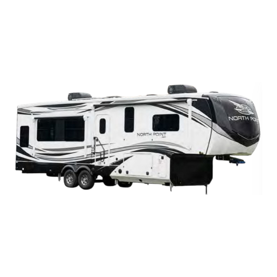
Summary of Contents for Jayco NORTH POINT 2023
- Page 1 NORTH POINT 2023 OWNER’S MANUAL S T R U C T U R A L WARRANTY A subsidiary of Thor Industries, Inc.
- Page 3 Suggestions For Obtaining Service Obtaining Service At Our Customer Service Facility Obtaining Service For Separately Warranted Items Parts and Accessories 2023 Jayco Limited Warranty Pinnacle, North Point, Eagle and Seismic 10 Section 2: Occupant Safety Secondary Means of Escape (Exit Window) Fire Safety...
- Page 4 Table of Contents Section 5: Slideout Systems Electric Slide Room(s) (if so equipped) Section 6: Electrical System The Electrical System Command Center GFCI Receptacle Command Control System (if so equipped) BMPRO RVMaster System (if so equipped) Inverter (if so equipped) Testing The Campsite Power Connection Power Converter 12-Volt DC System...
- Page 5 Table of Contents Section 10: Appliances Microwave Cooking Safety Cooktops, Range and Oven (if so equipped) Gas BBQ Grill (if so equipped) Range Hood (if so equipped) Refrigerator Washer/Dryer Prep (if so equipped) Central Vacuum System (if so equipped) Outside Kitchen (if so equipped) Section 11: Electronics Winegard Air 360 Plus System (if so equipped) Exterior Sliding / Pivoting TV...
- Page 6 Table of Contents...
-
Page 7: Section 1: Warranty & Service
Section 1: Warranty & Service WARNING: Read all instructions in this manual and component manufac- turer supplied information before using your RV. This manual has been provided by your recreational vehicle manufacturer for the sole pur- pose of providing instructions concerning the operation and maintenance of this recreational vehicle. - Page 8 Section 1: Warranty & Service Table of Contents...
- Page 9 Canada may differ to conform to Canadian Codes. Dealer Responsibility At the time of sale of the new recreation vehicle, your Jayco dealer is expected to: Deliver your recreation vehicle in the best condition possible. Your recreation ve- hicle must pass the dealer’s pre-delivery inspection (PDI), including all systems...
- Page 10 (or any effect of the alterations) to any of the parts, components, systems or assemblies installed by Jayco. Jayco is not responsible for the safety or quality of design features, materials or workmanship of any alterations by such suppliers.
-
Page 11: About This Manual
Section 1: Warranty & Service Failure to contact Jayco Customer Service, unauthorized or improper warranty repairs, or failure to return requested original parts may result in loss of reimbursements and/or loss of warranty. To Contact Us Mailing address Shipping address Jayco, Inc. -
Page 12: Safety Alerts
Section 1: Warranty & Service Safety Alerts Throughout this manual, certain items are labeled NOTE, NOTICE, CAUTION, WARN- ING, and DANGER. These terms will alert you to precautions that can involve risk to your vehicle or to your personal safety. Read and follow them carefully. -
Page 13: Reporting Safety Defects
Section 1: Warranty & Service Reporting Safety Defects In the United States: If you believe that your recreation vehicle has an alleged defect which could cause a crash or cause injury or death, you should immediately inform the National Highway Traffic Safety Administration (NHTSA), in addition to notifying our Cus- tomer Service Department. -
Page 14: Customer Responsibility
Section 1: Warranty & Service Customer Responsibility It is important you read and understand all instructions and precautions before operating the recreation vehicle. Even if you are an experienced RV’er we encourage you to thoroughly read this Owner’s Manual, as well as the information contained in your Warranty Packet. As technology advances, new improvements enter the RV industry every day, and each RV manufacturer has its own unique manufacturing process. -
Page 15: Obtaining Service At Our Customer Service Facility
Section 1: Warranty & Service require notification of any issues with their repairs within a specified time limit. Make sure you are familiar with their repair policies. Obtaining Service At Our Customer Service Facility Should your recreation vehicle be in need of service, and your dealer recommends that the repairs be made at our Customer Service facility, your recreation vehicle may be returned to us with the following guidelines*: You or your dealer must make a confirmed appointment 60 days prior to dropping... - Page 16 Canada and used for the intended purpose of recreational travel and camping. If a substan- tial defect in material or workmanship, attributable to Jayco, is found to exist and is reported to Jayco or an authorized servicing dealer during the applicable warranty period, it will be repaired or replaced, at Jayco’s option, without charge to the RV owner, in accordance with...
- Page 17 RV is delivered to the first retail purchaser by an independent, authorized dealer of Jayco, or, if the dealer places the vehicle in service before retail sale, on the date the RV is first placed in such service.
- Page 18 Section 1: Warranty & Service If you need assistance, you may contact Jayco, at 903 S. Main Street, P.O. Box 460, Middle- bury, Indiana 46540, Attn: Customer Service, (800) 283-8267. NOTE: Jayco does not control the scheduling of service work at the independent, authorized dealerships.
- Page 19 • vening acts not attributable to Jayco; • damage caused by unregulated water pressure, tank over fill, or plumbing system modi- fications resulting in flooding of the vehicle;...
- Page 20 In addition, this warranty is not intended to extend to future performance, and nothing in this warranty, or any action of Jayco, or any agent of Jayco, shall be interpreted as an extension of the warranty period or this limitation period.
- Page 21 ALSO HAVE OTHER RIGHTS THAT VARY FROM STATE TO STATE OR PROVINCE TO PROVINCE. ALL ACTIONS OF ANY KIND RELATING TO THE RV SHALL BE DECIDED BY A JUDGE RATHER THAN A JURY. JAYCO, INC. 903 S. Main Street * P.O. Box 460 * Middlebury, IN 46540 Telephone: (800)-283-8267...
- Page 22 Section 1: Warranty & Service Notes: Table of Contents...
-
Page 23: Section 2: Occupant Safety
Section 2: Occupant Safety Secondary Means of Escape (Exit Window) Your recreation vehicle has been equipped with a window(s) that serves as a secondary means of escape. The window(s) will allow a quick exit from the vehicle during an emer- gency if access to the main entrance door is not available. -
Page 24: Fire Safety
Section 2: Occupant Safety Lever style latch Remove the screen by pulling the red tab (upper right arrow). Pull the lever out from the sash clamps. Swing the lever out so it is positioned straight out from the win- dow. Push the lever (and window) out to open and exit the vehicle. -
Page 25: Smoke Alarm
Section 2: Occupant Safety Do not check the pressure, test or practice using the fire extinguisher by squeezing the trigger, even briefly. The fire extinguisher is not rechargeable or refillable. Once used, it will gradually lose pressure and will not be fully charged for use in an emergency. -
Page 26: Combination Carbon Monoxide /Propane Alarm
Section 2: Occupant Safety When the battery is removed from the alarm, the battery flag will pop up; the alarm cannot be installed to the mounting bracket without a battery. To test, stand at arm’s length from the smoke alarm as the alarm horn is loud and may be harmful to your hearing. - Page 27 Section 2: Occupant Safety Do not cover or obstruct the carbon monoxide/propane alarm with any- thing that could prevent gas from entering the alarm. This alarm is not designed to detect smoke, fire or gases other than car- bon monoxide and propane. The carbon monoxide detector installed is intended for use in ordinary indoor locations of recreation vehicles.
- Page 28 Section 2: Occupant Safety the vehicle was constructed (for more information, refer to Sec. 2, Formaldehyde). What you should do if the alarm sounds Actuation of this detector indicates the presence of carbon monoxide which can kill you. Never turn the 12-volt battery disconnect control to the off position and disconnect the battery cable to silence an alarm.
- Page 29 Section 2: Occupant Safety Alarm features and functions Includes an 85db audible horn, two LEDs, and a SILENCE/TEST button. Alarm States Normal operation: The Green LED is ON steady. Red LED OFF, Audible horn OFF. Power OFF: Both LEDs and the audible horn will be OFF. Self Test: Green LED OFF, Red LED ON/Flashing, audible horn 4 chirps fol- lowed by constant beeps.
-
Page 30: Extended Or Full Time Usage
Section 2: Occupant Safety To aid in dissipation, ventilate the recreation vehicle by opening all windows and circulate the air with a fan. This label is located inside the vehicle near the entry door and should be left permanently affixed to the rec- reation vehicle. -
Page 31: Section 3: Pre-Travel Information
Section 3: Pre-Travel Information Tow Vehicle If you plan to tow your recreation vehicle with a tow vehicle you already own, or if you plan to purchase a new one, make sure the Gross Vehicle Weight Rating (GVWR) or your recre- ation vehicle does not exceed your tow vehicles towing rating. - Page 32 Section 3: Pre-Travel Information Weight and Capacity Labels The following labels are typically located on the roadside front corner of the RV. An ad- ditional Occupant & Cargo Carrying Capacity label is also located on the inward surface of the entry door. OCCC Label (Occupant and Cargo Carrying Capacity): The upper portion of this yellow label is feder- ally required and includes the maximum Occu-...
-
Page 33: Loading Your Recreation Vehicle
Section 3: Pre-Travel Information Loading Your Recreation Vehicle Never load the RV in excess of the GAWR for either axle. Overload- ing your RV may result in adverse handling characteristics and dam- age to the RV. DO NOT EXCEED YOUR GVWR! This means you should weigh your RV as loaded for your normal travel to determine the actual weight. -
Page 34: Fifth Wheel Pin Box (Customer Supplied)
Section 3: Pre-Travel Information The rear bumper of your RV is not designed to carry cargo. Items that extend beyond the bumper OR weigh over 100 lbs. (45kg) will place undo strain on the bumper. The 100 lb. bumper capacity includes the weight of the spare tire (if so equipped). ™... -
Page 35: Wire Harness/Connector Plug
Section 3: Pre-Travel Information Fifth Wheel Hitching Procedure The following procedure will help to assist you in securely hooking up your recreation ve- hicle to your tow vehicle. Make sure the trailer wheels are blocked. Make sure the hitch lever is in its open or “cocked” position unless it has been designed to open automatically. - Page 36 Section 3: Pre-Travel Information Weighing Your Tow Vehicle and RV When the RV is fully loaded it should be weighed. The actual weight of the vehicle, all op- tions, liquids, the hitch weight, and your personal cargo is important for you to know so you do not exceed the GVWR.
- Page 37 Section 3: Pre-Travel Information overloaded, even though the total axle load is within the GAWR. Once actual weights are obtained, compare them to the Weight Information Label weight ratings to ensure you are below the posted minimum ratings. See the Weight Terms and Loading Your RV sections for important weight information. Table of Contents...
- Page 38 Section 3: Pre-Travel Information Notes: Table of Contents...
-
Page 39: Section 4: Vehicle Operation
Section 4: Vehicle Operation Towing If your RV is equipped with the Command Control Bluetooth system, make sure you turn off your battery disconnect switch according to the following instructions. BEFORE TOWING YOUR RV ON THE ROADWAY: TURN OFF THE BATTERY DISCONNECT SWITCH! Certain components inside the RV can unexpectedly activate which could result in personal injury or property damage. - Page 40 Section 4: Vehicle Operation clearance limits. The added height of roof air conditioners, TV antennas or floodlights may cause clearance problems around some tunnels, canopies and hanging signs. When turning, the tires do not follow the path of your tow vehicle tires. The RV will make a tighter turn than the tow vehicle.
-
Page 41: Towing Behind Your Rv
If you do not have a Jayco factory installed hitch receiver, towing items behind your Jayco RV, or overloading the rear, will void the warranty and may result in: damage to the RV or add-on items, towing difficulties, property dam- age and/or personal injury. - Page 42 Section 4: Vehicle Operation Factory Installed Hitch Receiver (if so equipped) If you do not have a Jayco factory installed hitch receiver, towing items behind your Jayco RV, overloading the rear, or failure to adhere to the specified weight capacities will void the warranty and may result in: damage to the RV or add-on items, towing difficulties, property damage and/or personal injury.
- Page 43 Section 4: Vehicle Operation Second Trailer Hitching Procedure The following procedure will help to assist you in securely hooking up the second trailer to your RV. Make sure the second trailer wheels are blocked. Turn the tongue jack crank to raise the trailer tongue above the hitch ball. Open the coupler latch on the trailer hitch.
-
Page 44: Entrance Door
Section 4: Vehicle Operation Stowable Entrance Door Step (if so equipped) Maximum Weight Capacity 500 lbs. Maintain hold of the steps until lowered all the way to the ground. Prior to use, legs must be adjusted properly to ensure the step is level. Ensure that both latches are engaged when the steps are stored. -
Page 45: Rear Backup Camera Prep
Section 4: Vehicle Operation Make sure the entrance door is completely closed and locked when traveling. Locking the door helps prevent it from opening unintentionally and keeps in- truders from your recreation vehicle. The entrance screen door may be equipped with a slide panel that allows access to the en- trance door handle and locks. - Page 46 Section 4: Vehicle Operation When using full hook-up, connect the sewer hose to the campsite sewer hook-up. If applicable, start the refrigerator and the cooling or heating system. ™ NOTE: For extended dry camping, management of all your resources is es- sential.
- Page 47 Section 4: Vehicle Operation F - Retract All button puts leveling system in full retract mode ™ NOTE: Pressing both the arrow buttons simultaneously turns on the touch- pad. Touchpad will time out after 7 minutes of non-use. Auto Level Touchpad LED Indicator status OFF - Touch pad is locked Solid Green - Touch pad is active Blinking Green - Jacks are moving...
- Page 48 Section 4: Vehicle Operation Hitch Recognition OneControl App (for phone or tablet) Download the OneControl App for your device from Google Play Store or ITunes. To access the OneControl App, ensure there is power to the RV’s wireless network hub. Navigate to the device’s Wi-Fi settings.
-
Page 49: Stabilizer Jacks
Section 4: Vehicle Operation Setting Zero Point Calibration ○ Zero point is the programmed point that the RVwill return to each time the Auto Level feature is used. Zero Point is only available on the OneControl Touch Panel. Preventative Maintenance tips Dexter EZ Flex Equalizer (if so equipped) Your recreation vehicle may be equipped with the Dexter EZ Flex Equalizer suspension. -
Page 50: Emergency Stopping
Section 4: Vehicle Operation ™ NOTE: The gears can be stripped out if the stab jack is manually retracted/ extended to its fullest extent and the operator continues to rotate the manual override. Emergency Stopping Always carry road flares or reflective warning signs. Pull off the roadway as far as possible for emergency stopping. - Page 51 Section 4: Vehicle Operation ™ NOTE: The proper method of tightening wheel lug nuts is with a properly calibrated torque wrench and socket, not with an impact wrench or by hand. Do not use a 4-way lug wrench or any other type of wrench that does not measure the actual pressure applied to the lug nut.
- Page 52 Section 4: Vehicle Operation Wheel Lug Nut Torque Values Prior to travel and after excessive braking, wheel lug nuts should be checked for torque. Torque readings must fall within the Final Torque Values in chart above. Torque specifications should be checked using a proper torque wrench. If the torque falls below the Final Torque Values, additional torque is required.
- Page 53 Section 4: Vehicle Operation • Damaged tools must not be used and must be removed from service for evaluation and either reported and re-calibrated or replaced. Do not use accessories or handle extensions unless specifically allowed by the torque wrench manufacturer. Do not use the torque wrench as the primary means of tightening or loosening fasteners.
- Page 54 Section 4: Vehicle Operation Tire wear should be checked frequently. Once a wear pattern becomes firmly established in a tire it is difficult to stop, even if the underlying cause is cor- rected. Tire pressure Failure to follow proper inflation guidelines may result in tire failure, which, under certain circumstances can cause loss of vehicle control or accidents that may result in property damage, bodily injury and/or death.
-
Page 55: Changing A Tire
Section 4: Vehicle Operation Changing A Tire Do not use the stabilizer jacks to support the recreational vehicle while under the vehicle or changing tires. The stabilizer jacks are designed as a stabilizing system only. Do not use the stabilizer jacks as a jack or in conjunction with a jack. - Page 56 Section 4: Vehicle Operation Depending on your model, the spare tire may have (side or bottom) brackets or it will be mounted against the underside of the recreation vehicle (flush mount) to give it stability in travel. Hoist Mount Travel Position Bracket Mount Travel Position ™...
-
Page 57: Setting Up Your Recreation Vehicle
Section 4: Vehicle Operation To install the tire on the tire carrier Place the tire on the carrier with the top lug bolt in- serted into one of the holes in the tire rim and the bot- tom lug bolt in the center of the rim. Install the top lug nut. -
Page 58: Awnings (If So Equipped)
Section 4: Vehicle Operation Awnings (if so equipped) Awnings must be closed (and secured) while the RV is in transit. Keep clear of arm assemblies while opening, adjusting or closing the aw- ning. Failure to obey this caution could result in injury and/or property damage. - Page 59 Section 4: Vehicle Operation slight “travel line” may appear where the door roller (if installed) contacts the fabric. This is normal and does not affect the integrity of the fabric. To clean the fabric: Open the awning. Mix 1/4 cup soap with five gallons of fresh water. Always use a natural soap, not a detergent.
- Page 60 Section 4: Vehicle Operation Notes: Table of Contents...
-
Page 61: Electric Slide Room(S) (If So Equipped)
Section 5: Slideout Systems Electric Slide Room(s) (if so equipped) The mechanical components of the slide out are gear driven. Electric powered slideout room systems have a manual override to allow you to extend or retract the slideout room(s) in case of a power loss. - Page 62 Section 5: Slideout Systems After the slideout is extended, visually inspect the slideout and the surrounding area to make sure the slideout has extended properly and has adequate clearance from any outside obstructions. If the slideout is equipped with rubber seals, verify that the corners of the black rubber seal are set up correctly.
- Page 63 Section 5: Slideout Systems and stops moving. Hold the switch in the IN position to retract the room. Release the switch, which will lock the room into position. If the slideout switch is held after the room is fully extended or retracted, the control will sense that the room has stopped and will shut the motor off after a few seconds.
- Page 64 Section 5: Slideout Systems ™ NOTE: Do not operate the switch after the room is fully extended or re- tracted as damage can occur to the motor and/or switch. To operate the slideout using a wireless remote (if so equipped): Press the on/off button to power on the remote.
- Page 65 Section 5: Slideout Systems Manual override for the in-wall slideout The slideout system comes with an “electronic” manual override. In event the slide out does not extend or retract follow these steps to override the system which should allow the slideout to be retracted.
- Page 66 Section 5: Slideout Systems Manually pushing in the slideout Locate the slideout system controller. Unplug motor 1 and motor 2 connectors at the bottom of the slideout controller. This releases the motor brakes for each motor. The slideout room can now be manually pushed in. Larger rooms may require several people to push or pull them.
- Page 67 Section 5: Slideout Systems Motors and cables are behind the interior fascia board around the slideout opening. Cables may stretch over time. Average stretch will be approximately 1/8” but it will not affect the function and does not require adjustment. Slideout runs off the DC power in the RV.
- Page 68 Section 5: Slideout Systems If the room still does not move when the switch is pressed, follow the steps below to manually override the slideout room: Turn the Main Power OFF. The override will not work if it has power going to it. Do not work on the system unless the battery is disconnected.
- Page 69 Section 5: Slideout Systems Power Gear Slim Rack Slideout System The Power Gear® Slim Rack slideout is typically used for slideouts 144” long and longer. It is operated by a 12VDC electric motor. The system is equipped with a manual over- ride allowing the room to be extended / retract- ed in the event of a power loss.
- Page 70 Section 5: Slideout Systems MAJOR and MINOR faults; faults must be cleared for the room to operate normally. MINOR faults can be cleared by pushing and releasing the IN or OUT buttons on the wall touchpad. MAJOR faults must be cleared by pushing and releasing the SET STOPS/CLEAR FAULTS button located on the back of the wall touchpad.
- Page 71 Section 5: Slideout Systems -Set parking brake (if ap- -Parking brake not set plicable) (if applicable) -Check for continuity to Park brake LED flashing -Ground signal lost at ground on wire plugged park brake control into park brake connector at control box.
- Page 72 Section 5: Slideout Systems It is very important to note that during this procedure, the slideout control has NO stop locations. Use a second person to assist in determining when the room is retracted. Damage to the room can occur if the room is retracted too far.
- Page 73 Section 5: Slideout Systems Power Gear Ram Slideout System Manual Override Procedure The system has been equipped with 3/4” hex override cou- plers located on the drive component of the system. Due to the size and weight of some rooms, assistance may be needed to push the room in.
- Page 74 Section 5: Slideout Systems The spring lock lever is a thin metal arm with a slight bend at the end, which will hold the brake lever in the released position. The brake lever is the heavier thicker metal arm with the hole in the end. The normal position for these two levers is to be parallel to each other as shown in the first side-by-side photo.
-
Page 75: Section 6: Electrical System
Section 6: Electrical System The Electrical System The RV electrical system is comprised of two independent electrical systems. One operates off of 12-volt DC power and the other off of 120-volt 60hz AC power. All installations have been made in compliance with industry standards applicable on the date of manufacture. Because the electrical equipment and associated circuitry are engineered into a dedicated system specific to your RV, do not make unauthorized changes or add fixed appliances to it. -
Page 76: Gfci Receptacle
Section 6: Electrical System Awning control switches (press and hold to extend / re- tract) Systems monitor with LED indicators for tank levels and battery charge status Auto leveling control panel (for leveling the RV) Inverter panel (power switch with display) Power bunk bed lift control switch Speaker selector switch Touch Dimmer Switch... - Page 77 Section 6: Electrical System Battery Levels Back Up Camera Systems Water Pump Kitchen and Bath Vents and Covers Door Locks TV, Radio and DVD Systems Automatic Fireplace Control Automatic Ramp Door (Toy Hauler) Propane Sensor Temperature Sensor ™ NOTE: On some systems, the switches turned on with a Control App or the touchscreen override switches at the command center panel.
- Page 78 Section 6: Electrical System Kitchen and bath vents and vent covers Door locks TV, radio and DVD systems Automatic fireplace control Lowering/raising the automatic ramp door (toy hauler) RVMaster Switches (remote controls) The system will come with multiple individual smart remote controls (or RVMaster Switch- es).
- Page 79 Section 6: Electrical System EXT Button – Used to extend either slideouts or awnings. Used in conjunction with the arrow buttons to select an awning or slideout (also used when pairing your smart phone or tablet to the system). RET Button – Used to Retract either slideouts or awnings. Used in conjunction with the arrow buttons to select an awning or slideout (also used when pairing wall mounted remotes to the system).
- Page 80 Section 6: Electrical System Unpairing Bluetooth devices Four Bluetooth devices can be paired to the system: the RVMaster Controller (touchscreen) and (3) other smart devices. The RVMaster Node will need to be cleared of ALL devices before re-pairing other devices. One device cannot be replaced with another device. To clear the RVMaster Node of all paired devices (which will also include the touchscreen): Go to the RVMaster App in your general settings on the touchscreen.
- Page 81 Section 6: Electrical System TPMS sensors – DO NOT MOVE WITH THE TIRES! The TPMS sensor on the front tire (on either side of the trailer) STAYS at the front tire position when rotating tires. The TPMS sensor on the middle tire (on either side of a 3 axle trailer) STAYS at the middle tire position when rotating tires.
- Page 82 Section 6: Electrical System Inverter (if so equipped) A factory installed inverter converts 12-volts DC to useable 120-volts AC and supplies con- tinuous AC power to the appliance plugged into it. It is important that you familiarize your- self with the inverter function and operation. The inverter should be “off” when not in use. ™...
-
Page 83: Testing The Campsite Power Connection
Section 6: Electrical System Refer to the Inverter manufacturers’ manual in your warranty packet for further operating instructions, error codes, changing inverter settings and safety information. Testing The Campsite Power Connection The campsite 120-volt power receptacle(s) should always be tested for proper functionality prior to plugging the recreation vehicle shore power cord into it. -
Page 84: Power Converter
Section 6: Electrical System Turn off the load center main 120-volt circuit breaker. Carefully extend the entire length of the power cord (approximately 25’-35’) from the electric cable hatch to the external power source. Plug the power cord into the receptacle. Be sure all the power cord prongs are properly plugged into the receptacle. - Page 85 Section 6: Electrical System the disconnected battery cables. If the voltage reads 13.6VDC with no load, the converter is functioning properly. If the converter output voltage at the battery reads in the 0.0VDC range, or the battery is not charging, check for: An open inline fuse in the battery wire An open wire between the converter and the RV battery Loose ground connection...
-
Page 86: Volt Dc System
Section 6: Electrical System Reverse Battery Protection: Reverse polarity fuse(s) provide protection for the converter when a battery is used. If the battery is connected backwards to the fuse board a fuse will blow preventing damage to the converter. Four easily accessible fuses are located next to the wizard button. -
Page 87: Auxiliary Battery (Customer Supplied)
Section 6: Electrical System Auxiliary Battery (Customer Supplied) Do not store anything inside the battery compartment(s) or near the batteries that could touch the battery or battery cable terminals. Contact with the battery or battery cable terminals could cause an electrical short circuit, discharge the batteries, or start an electrical fire. - Page 88 Section 6: Electrical System important to check the voltage monthly and recharge the auxiliary battery as needed. If you remove the auxiliary battery from your RV, store it in a dry, cool area per the manufacturer’s instructions. When it is time to replace the auxiliary battery, Group 27 or Group 31 true deep cycle batteries are recommended to increase run time of electrical components while dry camping (operating solely on battery power).
-
Page 89: Load Center
Section 6: Electrical System Load Center The Load Center contains 12VDC fuses and 120VAC circuit breakers for almost all of the electrical appliances and circuits in the RV. The 120V main breaker may be located in this panel and will turn off all 120-volt power to the RV. Load center location, appearance and configuration may vary by model. -
Page 90: Approximate Electrical Load Ratings
Section 6: Electrical System Replacement circuit breakers must be of the same voltage, amperage rating and type. Never use a higher rated replacement circuit breaker; doing so may cause a fire by overheating the RV wiring. Maintenance At the beginning of the camping season, inspect the circuit breakers and replace as needed. Test by turning each circuit breaker “off”... - Page 91 Section 6: Electrical System 120 VOLT SYSTEM Air Conditioner 18 AMPS Coffee Maker 6-12 AMPS Converter (each) 8 AMPS DVD System 3 AMPS Fireplace 15 AMPS Hair Dryer or Curling Iron 10-14 AMPS Microwave 15 AMPS Refrigerator 6 AMPS Satellite Receiver 2 AMPS 2-4 AMPS Vacuum Cleaner...
- Page 92 Section 6: Electrical System 50 AMP Power Cord Do not hook up the power cord to any receptacle until you have verified proper polarity and grounding. Polarity indicators can be purchased in most electrical and hardware stores. Do not use any cheater plug, adapter or extension cord to reconfigure incoming AC power or break the continuity of the circuit connected to the grounding pin.
- Page 93 Section 6: Electrical System CARBON MONOXIDE IS DEADLY! Do not run the generator when your RV is indoors or in a confined space. Asphyxiation or carbon mon- oxide poisoning hazards exist whenever generator exhaust gasses can accu- mulate. MOVING PARTS AND ELECTRICITY can cause severe personal injury or death.
- Page 94 Section 6: Electrical System service work should be done by a repair facility authorized by the generator OEM. Improper adjustments can damage the generator and electrical appliances, and can result in a safety hazard. If any discrepancy or problem is noted, contact your dealer for assistance. Exercising Your Generator –...
-
Page 95: Solar Prep (If So Equipped)
Section 6: Electrical System Solar Package (if so equipped) If expanding upon OEM installed solar package, ensure all components are compatible with existing product. Any additional equipment will reduce Car- go Carrying Capacity (CCC) when installed. Your recreational vehicle may be equipped with a factory installed solar panel kit that in- cludes lithium batteries, a DC/DC power converter (allows charging from the tow vehicle connection.), Solar Panels, and an energy management control system. - Page 96 Section 6: Electrical System Notes: Table of Contents...
-
Page 97: Exhaust Gas Fumes
Section 7: Fuel & Propane System Exhaust Gas Fumes Avoid inhaling exhaust gases as they contain carbon monoxide, which is a potentially toxic gas that is colorless and odorless. If you are in a recreation vehicle with either a nearby tow vehicle engine running or the generator (if so equipped) running there is a potential for exhaust fumes to filter back into the recreation vehicle. - Page 98 Section 7: Fuel & Propane System recommended. Hand tighten the LP gas system valves only, do not use a wrench or pliers as over tightening may damage the valve seals and cause them to leak. ™ NOTE: All propane lines have been checked with air pressure at the time of manufacture.
- Page 99 Section 7: Fuel & Propane System ASME tanks are permanently mounted to the RV and are commonly used on RV mo- torhomes. The capacity of ASME tanks is expressed in gallons. ASME tanks are filled while the tank is attached to the motorhome by a qualified propane facility. ASME tanks are equipped with an automatic stop fill valve designed to reduce the potential of overfilling.
- Page 100 Section 7: Fuel & Propane System The propane piping system is designed for use with propane only. Do not connect natural gas to this system. This label should be kept permanently affixed to your RV. Refer to your Warranty Packet for more information on the LP gas system components.
-
Page 101: Propane Use And Safety
Section 7: Fuel & Propane System Propane Regulator Propane regulators must always be installed with the regulator vent facing downward. Regulators that are not located in baggage compartments have been equipped with a protective cover. Make sure the regulator vent faces downward and (if applicable) the cover is in place to minimize vent blockage that could result in excessive gas pressure causing fire or explosion. - Page 102 Section 7: Fuel & Propane System Propane Leak Test Leaks may be found easily with a soapy water solution. Do not use a solution containing ammonia or chlorine when locating leaks. These products are corrosive to copper gas lines and brass fittings, which could result in deterioration of the copper and brass components. Apply the soapy solution to the outside of the gas piping fittings.
- Page 103 Section 7: Fuel & Propane System It is especially important that cooking appliances not be used for comfort heating, as the danger of asphyxiation is greater when the appliance is used for long periods of time. FAILURE TO COMPLY MAY RESULT IN DEATH OR SERIOUS INJURY. These warning labels are located in the cooking area to remind the user to provide an ad- equate supply of fresh air for combustion.
-
Page 104: Installing Propane Cylinder(S)
Section 7: Fuel & Propane System All pilot lights, appliances and their igniters (see operating instructions) should be turned off before refueling of motor fuel tanks and/or propane containers. These can cause ignition of flammable vapors, which can lead to a fire or explosion. - Page 105 Section 7: Fuel & Propane System Attach the 1/4” inverted flare x 18” Type-1 pigtail hose to the regulator inlet and the right hand swivel nut to the cylinder valve. Main Supply Hose – Low Pressure Attach the main supply hose from the regulator to the brass manifold fitting in the frame of the Main Supply Hose trailer.
- Page 106 Section 7: Fuel & Propane System Notes: Table of Contents...
-
Page 107: Plumbing System
Section 8: Plumbing System Plumbing System There are two different water systems in your recreation vehicle: The fresh water system consists of the fresh water holding tank, faucets and con- nections, water pump, water heater, tub/shower. On some models, it may also include the water purification system or outside shower assembly (if so equipped). -
Page 108: Fresh Water System
Section 8: Plumbing System F = Fair at 11.6 volts L = Low at 6.0 volts Tank monitors on the touch screen have a constant readout. There are no buttons to push. Tank levels are displayed by percentage from 0% to FULL. Level Alert Button (if so equipped): some models may be equipped with a Level Alert Button. - Page 109 Section 8: Plumbing System DO NOT drink water deemed microbiologically unsafe or of unknown quality. Avoid traveling with full fresh, black or grey water holding tanks. The weight of holding tank contents in not calculated into the RV cargo car- rying capacity.
-
Page 110: Water Purification System (If So Equipped)
Section 8: Plumbing System 12-volt Water Pump There must be sufficient 12-volt DC power to run the water pump when your recreation vehicle is not hooked up to city water. Once activated, the water pump (also known as the demand pump) will self- prime, and provide water. -
Page 111: Draining The Fresh Water System
Section 8: Plumbing System Do not allow water in the canister housing to freeze. Remove the filter before using anti-freeze to winterize the system or chlorine solution to sanitize the system. Flush canister housing thoroughly before it is put back into service after winterizing or sanitizing. - Page 112 Section 8: Plumbing System These low-point drains will release water in the supply lines by opening the valves and all faucets. The water heater has its own drain plug. To drain the permanent fresh water holding tank and supply lines: Turn the water heater power OFF (turn off the electric and LP gas switches).
- Page 113 Section 8: Plumbing System Utility Center (P4) (if so equipped) The Utility Center is located in an exterior compartment and allows you to perform the following functions: Power fill the fresh water tank for remote or dry camping Use the pump to supply water to fixtures from the fresh water tank Use the pump to siphon fill or sanitize the fresh water tank from a bucket Connect to city water at the camp site to supply water to RV fixtures Winterize the plumbing lines and fixtures...
- Page 114 Section 8: Plumbing System A check valve is located inside the city water connection inlet on the utility center. NEVER depress the check valve on the “CITY WATER CON- NECTION” inlet with pressure in the line. It will cause irreparable damage to the valve function and the inlet will leak water.
- Page 115 Section 8: Plumbing System Dry Camping (pump supplies water from the fresh water tank) Make sure the fresh water tank has an adequate supply of water. Set the color coded valves to the DRY CAMPING setting: Blue handle pointing left White handle pointing down Red handle pointing up Green handle pointing up...
- Page 116 Section 8: Plumbing System ™ NOTE: Filters should be replaced at the beginning of the camping season or if they have been exposed to contaminated water, sanitizer or antifreeze. Attach a short section of garden hose to the CITY WATER inlet at the utility center. DO NOT use your fresh water hose for sanitizing.
- Page 117 Section 8: Plumbing System ™ NOTE: To thoroughly sanitize the fresh water tank, the unit should be driven around for a short distance allowing the solution to splash the sides and top of the tank. 15. After the required period, drain the chlorine solution from the fresh water system. Rinse the system with fresh water 16.
- Page 118 Section 8: Plumbing System Set the colored valves to the SANITIZE setting. Blue handle pointing down White handle pointing right Red handle pointing up Green handle pointing left Attach a short hose to the CITY WATER inlet. Put the other end of the hose in a con- tainer with the vinegar solution.
- Page 119 Section 8: Plumbing System ™ NOTE: The winterization process may vary slightly due to different plumb- ing configurations between models. Appliances (refrigerator, dishwasher or clothes washer) must be winterized. Re- fer to the appliance owner's manual for additional information or contact your Dealer or Customer Service for assistance.
- Page 120 Section 8: Plumbing System 10. Repeat with all the cold water line faucets (kitchen/bath sinks, shower, outside shower, and outside kitchen (if equipped). Toilet: Flush the toilet several times until you see antifreeze in the bowl. When you are finished adding RV antifreeze: 11.
- Page 121 Section 8: Plumbing System Full System Canister Filter: Remove the can- ister lid, take out the filter and then re-attach the lid on the empty canister. Cartridge Water Filter: Remove the car- tridge filter and replace it with a bypass hose (supplied with your RV).
-
Page 122: Water Heater
Section 8: Plumbing System Water Heater Your RV may be equipped with either a tank (storage) water heater or tank less water heater. The following is an overview of both systems. Hydrogen gas may result if you have not used the water heater for two weeks or more. - Page 123 Section 8: Plumbing System If lock-out occurs before the main burner lights, turn the water heater control switch to OFF, wait five seconds and turn the switch to the ON position. This will restart the ignition cycle. The first start-up of the heater may require several ignition cycles before all the air is purged form the propane lines.
- Page 124 Section 8: Plumbing System This “weeping” or dripping will continue until the pressure is reduced to below 150 pounds, and the valve closes. This condition is normal and does not indicate a defective relief valve. One way to reduce the frequency of this occurrence is to maintain an air pocket at the top of the water heater tank.
- Page 125 Section 8: Plumbing System valve for winterizing. It is not affected by high altitudes. The output temperature of the water depends on the temperature of the inlet water AND the amount of hot water that is drawn. If the inlet water temperature is over 65 º F, the tankless water heater will generate water in the range of 105°F to 120°F (on low flame) depending on the water flow selected by the user.
- Page 126 Section 8: Plumbing System Maintenance Inspect your water heater monthly and have it serviced at least once a year by the manufac- turer’s recommended service technician. If you have questions, contact your RV dealer, the manufacturer, or Customer Service. TRUMA® Tankless Water Heater (if so equipped) Your recreation vehicle may be equipped a Truma®...
- Page 127 Section 8: Plumbing System door (photo B). Lower the door so it lays flat against the RV hanging down by the straps (photo C). To close the door, insert the tabs back into the slots at the bottom of the door, close the panel and rotate the locking knob.
- Page 128 Section 8: Plumbing System Aqua Go COMFORT PLUS MODELS ECO MODE: The water heater is run- ning in energy saving mode. Propane gas is used to prevent freezing. The temperature in the water heater is auto- matically kept above 41°F (5°C). Water temperature coming out of the fixtures is approximately 120°F (49°C).
- Page 129 Section 8: Plumbing System ™ NOTE: If the inlet filter is difficult to re-install, use a small amount of soap on the O-rings. NEVER USE GREASE as the O-rings are not resistant to grease. When the drain chute is folded out, it protrudes past the sidewall of the When walking past or stooping down, make sure you and others have sufficient clearance to prevent injuries.
-
Page 130: Outside Shower (If So Equipped)
Section 8: Plumbing System Decalcification BASIC MODEL Lime scale occurs as a result of precipitation from “hard” water. The appliance must be decalcified regularly depending on water hardness and hot water consumption. Decalcifica- tion must be done through your RV dealer. Specialized equipment is required and cannot be easily accomplished by the owner. -
Page 131: Black/Grey Water System And Tanks
Section 8: Plumbing System If dry camping, be sure your 12-volt water pump is ON. Unlike your home, the recreational vehicle does not contain a water pressure balance valve. If someone is using the shower, it is recommended that the fresh water system NOT BE USED until they are finished. - Page 132 Section 8: Plumbing System REMOVE WATERLESS TRAP BEFORE USING MECHANICAL DRAIN CLEANING DEVICES Sewer Hose Storage Depending on your RV model, the sewer drain hose may be stored in an exterior compart- ment marked “Sewer Hose” or it may be located in the hollow square tube bumper. The bumper has removable plastic end caps, and the hose slides inside the hollow bumper.
- Page 133 Section 8: Plumbing System Before using the recreation vehicle, or after dumping the grey and black water holding tanks, always add the proper amount of deodorant to the black water tank to prevent odors and help break down holding tank contents (unless winterizing). Follow the deodorant bottle or package instructions.
- Page 134 Section 8: Plumbing System Cleaning and Maintenance The toilet should be cleaned regularly for maximum sanitation and operational efficiency. Use only RV approved chemicals. Do not use chlorine (undiluted) or caustic chemicals, such as laundry bleach or drain opening types, in the toilet system. These products damage the seals in toilets and dump valves.
- Page 135 Section 8: Plumbing System The black tank flush inlet can be used with this system also (refer to the Black Tank Flush section). The Macerator Bypass Valve is located underneath the external hose storage box. This by- pass will allow you to gravity dump the waste from the tanks straight down to a 3-inch sewer hose connection under the trailer, in the event there is a problem with the macerator motor.
-
Page 136: Black Tank Flush (If So Equipped)
Section 8: Plumbing System De-winterize the macerator system: Emptying the black tanks in the spring will flush antifreeze out of the macerator system. Black Tank Flush (if so equipped) The black tank flush (no fuss flush) inlet is typically located on the utility center panel (if so equipped) labeled as “Tank Flush”. -
Page 137: Tank Heaters (If So Equipped)
Section 8: Plumbing System Open the waste gate valve for the black tank (under the RV). ™ NOTE: If the RV has a macerator system, you need to open the bypass valve for the macerator under the RV. This will allow the black tank to drain through the 4”... - Page 138 Section 8: Plumbing System • In order for the 120VAC tank heaters to be in operation, the recreation vehicle MUST be hooked up to shore power or under generator power. • If the recreation vehicle is not operating on shore power or generator power, only the +12VDC heaters will operate.
- Page 139 Section 8: Plumbing System enough water to prevent solid waste buildup. The following guidelines will help to prevent solid waste buildup. Sewage (black) tank preparation Release one to two quarts (1 or 2 liters) of water into the toilet bowl. Follow the directions on your (approved RV) toilet chemical bottle (customer sup- plied), by placing the recommended quantity of holding tank chemical into the toilet bowl.
- Page 140 Section 8: Plumbing System Notes: Table of Contents...
-
Page 141: Air Conditioner
Section 9: Heating & Cooling Air Conditioner Cooled air enters the RV through the grill. Make sure you have sufficient power available before operating the air conditioner. Do not operate the air conditioner without the return air filter. Operating the system without the filter allows the lint and dirt that is normally stopped by the filter to accumulate on the cooling coil of the air conditioner. -
Page 142: Fireplace (If So Equipped)
Section 9: Heating & Cooling (located on the fan) controls the direction of operation (down for forward, up for reverse). Stop the fan first before reversing the operation direction! ™ NOTE: During cooler temperatures, set your fan settings to "low," and set the fan to turn clockwise to pull warm air from the ceiling back towards the floor. -
Page 143: Section 10: Appliances
Section 10: Appliances Microwave To prevent damage, remove the turntable from the microwave when trav- eling. Make sure you are connected to a 120-volt power source. Never use the microwave cavity for storage. The microwave cavity should always be empty when not in use. For details on operation, cleaning and safety information, refer to the manufacturer’s user guide. - Page 144 Section 10: Appliances Cooking With Propane (if so equipped) See the Propane System section for important safety instructions. Refer to the manufactur- er’s owner’s manual for detailed operating and safety instructions for all propane appliances. Cooktops, Range and Oven (if so equipped) For detailed operating and safety information, refer to the manufacturer’s user guide.
- Page 145 Section 10: Appliances Gas Drop-In Cooktops (if so equipped) Depending on your model, it may be equipped with either a 2 burner or 3 burner cooktop. The 2 burner match-light cooktop has two 6500 BTU/H burners with control panel. The 3-burner piezo-igniter cooktop has (1) front 9000 BTU/H burner and two rear 5200 BTU/H burners.
- Page 146 Section 10: Appliances Always open hood before turning on gas and lighting burner, failure to open the hood before lighting could cause an explosion causing property damage, injury, or even death. ™ NOTE: This outdoor cooking warning label should not be removed from the RV. Depending on your model, your grill will be mounted with either a bumper mount system, or a rail mount on the side of your recreational vehicle.
-
Page 147: Range Hood (If So Equipped)
Section 10: Appliances Range Hood (if so equipped) If your recreational vehicle is equipped with a range hood, it will be connected to an exterior vent. The vent has an inner flap with two snaps. This flap can be snapped shut when the vehicle is in motion, or during storage to keep in- sects, debris, snow, rain, etc. -
Page 148: Washer/Dryer Prep (If So Equipped)
Section 10: Appliances Cleaning the Interior Unplug refrigerator or disconnect power. Hand wash, rinse, and dry removable parts and interior surfaces thoroughly. Use a clean sponge or soft cloth and a mild detergent in warm water. Inside the refrigerator, use a warm water and baking soda solution consisting of ap- proximately 1-tablespoon (15ml) baking soda to 1 quart (1 liter) of water. -
Page 149: Outside Kitchen (If So Equipped)
Section 10: Appliances Gas dryers should NEVER be installed in your recreation vehicle. Dryer prep has been designed for electric dryer operation ONLY. Do not operate a dryer in the recreation vehicle unless the dryer is properly vented. Central Vacuum System (if so equipped) The following is an overview of the central vacuum system operation. - Page 150 Section 10: Appliances Make sure all supports are securely in place before using the outside kitchen. Before using, make sure the propane connection is properly hooked up and secure. Do not leave the cooktop unattended while using. Keep all clothing and flammable material away from the cooktop while in use. Do not exceed the weight capacity of the outside kitchen unit.
- Page 151 Section 10: Appliances The grill requires proper ventilation. It is designed for RV outdoor use only. NEVER put lava rocks or charcoal or anything else on or under the grate. The grill is designed so it does not require those items. Serious injury or property damage can occur by placing foreign objects on the grate.
- Page 152 Section 10: Appliances Notes: Table of Contents...
- Page 153 Section 11: Electronics Winegard Air 360 Plus System (if so equipped) The Winegard Air 360 Plus system is a fixed omnidirectional TV/FM antenna, plus Wi-Fi, and 4G extender. The enclosure is 8 inches high and 17 inches in diameter. Antennas are powered by +12VDC supplied with a cable attached to the enclosure.
- Page 154 Section 11: Electronics Bluetooth control The Bluetooth function on your smartphone, tablet or other smart device must be enabled in order to detect the SSID from the router and connect to the system. ™ NOTE: You MUST turn the power switch ON or there will be no cellular or Wi-Fi signals from the router box.
- Page 155 Section 11: Electronics ™ NOTE: The TV does not lock into place when it is in the pivoting position. Retracting the TV for storage Rotate the TV back into the storage position so the T-handle locks back in place to keep the TV from pivoting (E).
- Page 156 Section 11: Electronics Notes: Table of Contents...
-
Page 157: Cleaning The Interior
Section 12: Interior Cleaning The Interior To keep the value of your recreation vehicle, perform regular maintenance using the proper materials and procedures. Using the wrong cleaner may result in damage to the surfaces in your vehicle. Check with the manufacturer’s information for the recommended cleaning agent. - Page 158 Section 12: Interior Fill a spray bottle with water and a tiny amount of soap. Then spray a lint-free towel with the mixture and use the towel to wipe down each slat. While cleaning, try not to bend the slats. They can also be soaked in a bathtub to loosen up any debris so the slats can be wiped down easily.
- Page 159 Section 12: Interior down to provide a sleeping surface. For additional comfort and to reduce fabric damage, you may want to place a cover or air mattress (customer supplied) over the sofa when it is in the sleeping position. Trifold Sofa The trifold sofa offers very similar features to a traditional hide-a-bed.
-
Page 160: Pantry Or Hutch (If So Equipped)
Section 12: Interior Free-Standing Table and Chairs (if so equipped) The free-standing dinette table can be positioned to seat up to four people. To prevent dam- age, the free-standing dinette chairs should be fastened securely at the dinette table when traveling. - Page 161 Section 12: Interior remove watermarks. Difficult stains can be removed from the matte finish with a green Scotch Brite® pad and a mild abrasive cleaner. Disinfect the surface periodically with diluted household bleach (one part water to one part bleach). For cuts and scratches, sand the matte finish lightly with (220) fine grit sandpaper until the cut or scratch is gone.
-
Page 162: Bed Storage
Section 12: Interior dish detergents or vinegar and water because they will dull your floor. To care for the vinyl floor covering, use a damp mop with water and a mild cleaner on the entire floor. DO NOT SOAK THE FLOORING. Use care to avoid wetting the carpet edges. To avoid problems of “yellowing”... - Page 163 Section 12: Interior Some models may be equipped with a prop rod or gas struts to assist with easy access to under bed storage. Prop Rod (if so equipped) If your model is equipped with a prop rod: With the help of a second person, raise the bed platform. Release the prop rod from its holder.
- Page 164 Section 12: Interior Exercise extreme care when climbing up or down the ladder used for entering or exiting the loft bed. Closet door MUST be securely closed and latched before using the lad- der. Make sure the ladder is securely in place prior to climbing to or from the loft.
- Page 165 Section 12: Interior Exercise extreme care when entering or exiting the bunk beds and using the ladder. Do not allow more than one person on the top bunk. Do not allow children under 6 years of age to use the upper bunk. Do not allow horseplay on or under the bed and prohibit jumping on the bed.
- Page 166 Section 12: Interior Notes: Table of Contents...
-
Page 167: Cleaning The Exterior
Section 13: Exterior Cleaning The Exterior To protect your recreation vehicle’s exterior finish, wash it often and thoroughly. You may wash and wax your new recreation vehicle 60 days after purchase. The exterior paint needs time to cure before any wax is applied to the exterior surface. Careful maintenance for the first 60 days will assure a long lasting durable finish. - Page 168 Section 13: Exterior During cold weather Salt and other chemicals that are spread on winter roads in some geographical areas can have a detrimental effect on the recreation vehicle’s underbody. If your recreation vehicle is exposed to these conditions, spray the underbody with a high-pressure hose every time you wash the exterior of your recreation vehicle.
-
Page 169: E-Z Lube Or Super-Lube Axle (If So Equipped)
Section 13: Exterior Do not allow plastic to come into contact with brake fluid, engine oil, grease, paint thinner, or battery acid. These will damage plastic. Use a soft cloth and a mild detergent solution to wipe away any such contact. Chrome parts To prevent chrome parts from spotting or corroding, wash with water, dry thoroughly, and apply a non-abrasive automotive wax. - Page 170 Section 13: Exterior If your recreation vehicle is equipped with a roof ladder, do not leave items attached to it while traveling. DO NOT exceed the weight rating of the ladder. The ladder weight capacity label is located under the bottom step of the ladder.
- Page 171 Section 13: Exterior Sealants Failure to properly maintain or reseal your recreation vehicle may result in serious water damage to the roof and other parts of the recreation ve- hicle. This damage is not covered by the Limited Warranty. To check the exterior sidewall sealants, use a stepladder placed safely alongside the vehicle.
- Page 172 Section 13: Exterior Fifth Wheels - Sealant Diagram Table of Contents...
-
Page 173: Section 14: Travel/Camping/Storage Checklists
Section 14: Travel/Camping/Storage Checklists Travel Checklist Following is a preliminary list of items that need to be checked before leaving your home or campsite. This is a general list, which you may want to customize as you determine your own needs. Safety Make sure you follow all safety precautions noted in this owner’s manual and in any manufacturer’s operators manual when preparing to travel. - Page 174 Section 14: Travel/Camping/Storage Checklists Before leaving the campsite Check the area under the RV after overnight parking and look for water or other fluid leaks. If leaks are detected, find the cause and correct it immediately. Turn off propane tanks. Empty black and gray holding tanks, rinse as needed (if so equipped).
- Page 175 Section 14: Travel/Camping/Storage Checklists Close the propane cylinder valve(s). We recommend using a propane cylinder cover, and to make sure the propane regulator is covered. If is equipped with a gas/ electric DSI range, light a range gas burner to consume any gas remaining in the lines.
- Page 176 Section 14: Travel/Camping/Storage Checklists Notes: Table of Contents...
-
Page 177: Featured Components Quick Reference Chart
Your recreation vehicle may be equipped with some of the items listed below. This is a partial listing and it is not intended to cover all components. All information is the latest available at the time of publication. Jayco reserves the right to change any of the following information without notice. - Page 178 Section 15: Additional Information Thermostat Coleman Mach www.airxcel.com/coleman-mach Toilet Thetford Corp. www.thetford.com See manufacturers’ user guide Winegard Company www.winegard.com TV Antenna King Jack www.kingconnect.com Water Heater, Tank DSI Atwood Greenbrier www.atwoodmobile.com Girard Systems www.greenrvproducts.com Water Heater, Tankless Truma AquaGo www.truma.com Shurflo East www.shurflo.com Water Pump, 12V...
-
Page 179: Vehicle Maintenance Record
Section 15: Additional Information Vehicle Maintenance Record Make: Model: Model Year: Vehicle Serial#: Service Performed Mileage Work Performed Notes Date Table of Contents... - Page 180 Section 15: Additional Information Jayco Ownership Notification Email the form to unitfile@jayco.com ATTENTION! Federal record keeping laws require that we maintain a file of owners of our product. Your cooperation in filling out this from will be appreciated. □ □...
- Page 181 Section 15: Additional Information Notes: Table of Contents...
Need help?
Do you have a question about the NORTH POINT 2023 and is the answer not in the manual?
Questions and answers