Advertisement
PRESENTATION
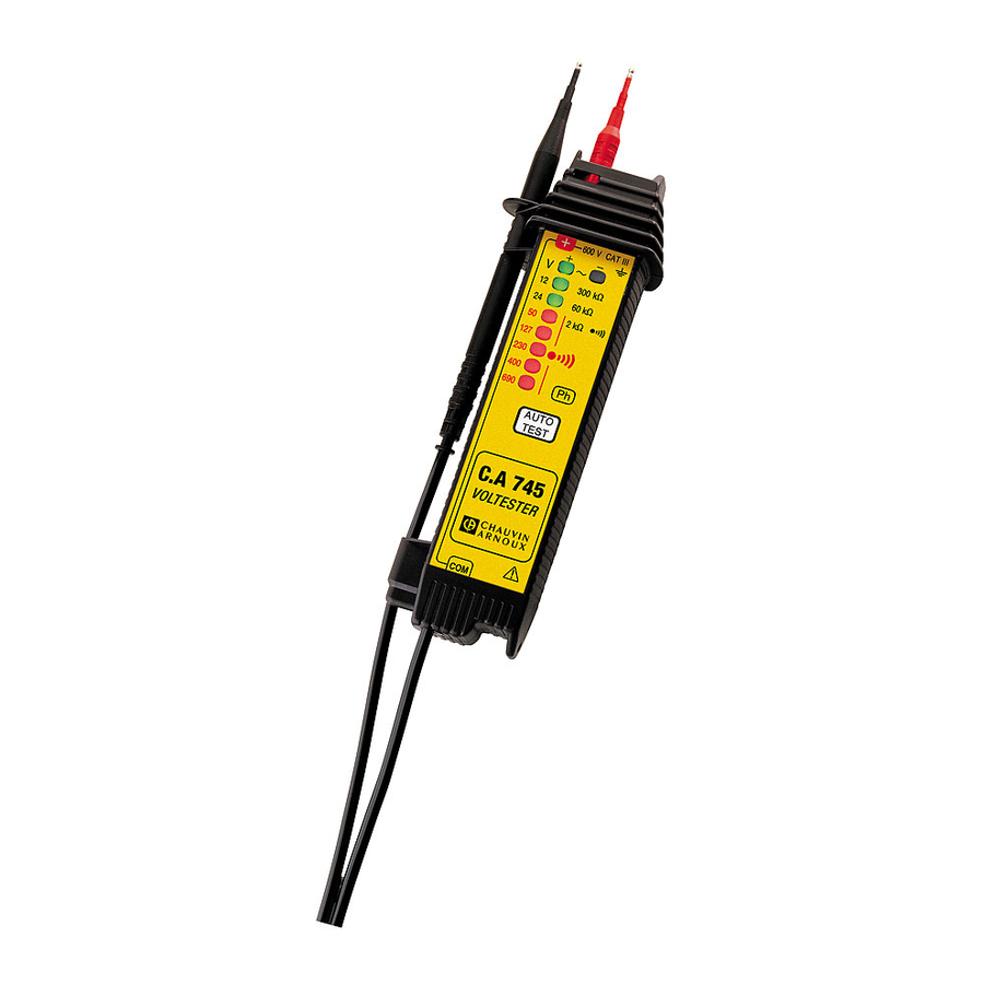
The C.A 745 is an audible and visual DC and AC voltage, continuity and resistance tester. It also has a phase/neutral identification function. Its maximum operating voltage, 690 V, allows tests on a 3-phase 400 V/ 690 V installation whilst respecting the max voltage in relation to the earth of 600 V.
This tester does not have a fuse and its design avoids risks of internal short circuit.
- Test prods (with 19 mm gap)
- Non-slip guard to avoid any accidental contact with a live conductor
- Ramp of LED's giving the value of the voltage
- AUTO-TEST: test button
- Continuity button on the back of the case
AUTO-TEST
The auto-test allows testing of the correct operation of the complete tester: test prods with light emitting diodes (LED), via the lead, the electronics and the 9 V battery.
NB: Never use the tester if the auto-test is negative.
How to do the auto-test
Press the AUTO-TEST button
- The «+» LED and the 12 to 690 V LED's light up, and the buzzer comes on.
- Short-circuit the test prods, with the AUTO-TEST button still pressed: the «-» LED lights up. The tester is in good working condition if all the LED's light. If not, change the 9 V battery (see §.Maintenance) and do the auto-test again.
VOLTAGE TEST
 Always do an AUTO-TEST before using the tester. Do not press the «continuity» button on the back of the tester.
HOW TO USE
Place the red test prod in position in the lockable «+» terminal. Hold the tester in your hand, without pressing the AUTO-TEST button, and place the test prods at the terminals of the circuit to be tested. The simple presence of a voltage ensures automatic operation.
RECOGNITION OF DC OR AC
- Both green LED's «+» and «-» light up: AC voltage
- The «+» LED lights: DC, positive at the test prod of the tester
- The «-» LED lights: DC, negative at the test prod of the tester
- No LED lights up: no voltage or voltage < 12 V.
VALUE OF THE VOLTAGE
- 2 green LED's: 12 V and 24 V
- 5 red LED's: 50 V, 127 V, 230 V, 400 V and 690 V The last LED lit gives the level of voltage present. Lights to 85% of the nominal voltage.
![]() : Emission of continuous audible buzzer simultaneously with lighting of the red LED's (U > 50 V).
: Emission of continuous audible buzzer simultaneously with lighting of the red LED's (U > 50 V).
![warning]() In case of bright sunlight, the visual perception of the presence of voltage may be affected.
In case of bright sunlight, the visual perception of the presence of voltage may be affected.
 : Emission of continuous audible buzzer simultaneously with lighting of the red LED's (U > 50 V).
SPECIFICATIONS AND DOMAIN OF USE
- Voltage detection: 12 V ≤ U ≤ 690 V
- Frequency: 0...400 Hz
- Maximum voltage in relation to the earth: 600 V
- Permited overload: 1000 Vrms for 30 seconds
- Consumption: variable depending on the voltage. 125 µA at 50 V and 1.7 mA at 690 V
- Impedance: 400 kΩ
- Response time: < 0.5 seconds
- Duration of test: unlimited for U ≤ 690 Vrms.
PHASE / NEUTRAL IDENTIFICATION
Always perform an AUTO-TEST before using the tester
Bring the black test prod into contact with the circuit to be tested. In the presence of phase (U > 100 V) the «Ph» LED flashes. In certain cases, the «Ph» LED may light up in the presence of static charges.
CONTINUITY AND RESISTANCE TEST
Always perform an AUTO-TEST before using the tester. Never make a resistance test on a live circuit
HOW TO USE
Place the test prods at the terminals of the component or the circuit to be tested. Press the «continuity» button on the back of the tester.
VALUE OF RESISTANCE
- 2 green LED's: 300 kΩ and 60 kΩ (to nearest 25%)
- 1 red LED: 2 kΩ The last LED lit gives the value of the resistance present; value below that marked on the tester.
CONTINUITY SOUND TEST
A continuous buzzer sounds simultaneously with lighting of the red LED «  »: R ≤ 2 kΩ
SPECIFICATIONS
- Impedance: 12 kΩ
- Max test current: 100 µA
- Empty voltage test: 3.8 V
- Positive polarity on the test prod of the tester
- Response time: < 0.5 seconds
- Protection: up to 550 V (consumption < 20 mA for 230 V. Does not trigger 10 and 30 mA RCD's)
DIODE TEST
The diode test is done in exactly the same way as the continuity test; to check the direction of conduction (or reverse) of diodes, transistors,...
GENERAL SPECIFICATIONS
ENVIRONMENTAL CONDITIONS
Conditions to respect to guarantee good operation
- Use indoors.
- Temperature: -10...+55°C
- Relative humidity: 10...90% RH
- Altitude: up to 2000 m
POWER SUPPLY
- 1 battery 9 V (6 F 22, 6 LF 22 or NEDA 1604)
- Battery life:
- 5000 tests of 5 seconds with alkaline battery (6 LF 22)
- 3500 tests of 5 seconds with ordinary battery
DIMENSIONS AND WEIGHT
- Dimensions: 193 x 47 x 36 mm (outside)
Weight: 170 g (with battery) - Length of lead: 1.20 m
- Diameter of test prods: 2 mm and 3.7 mm
CONFORMITY WITH STANDARDS
- DIN - VDE 0680 - Part 5: German standard defining dual pole voltage testers.
- Electrical safety
![]()
(to IEC 61010-1, IEC 61010-2-033)- Double insulation
- Installation category III
- Degree of pollution 2
- Rated voltage: 600 V (in relation to the earth)
- Watertightness (to NF EN 60529):
Protection index IP 50 - Electromagnetic compatibility:
Emissions and immunity in an industrial setting compliant with EN 61326-1

MAINTENANCE
For maintenance, use only specified spare parts. The manufacturer will not be held responsible for any accident occurring following a repair done other than by its After Sales Service or approved repairers.
REPLACING THE BATTERY
Always disconnect the tester from any electric source before opening the case
- Remove the two screws from the lower half of the case
- Replace the used 9 V battery by a battery of the same type (6 F 22, 6 LF 22 or NEDA 1604)
- Close the case again before using the tester
CLEANING
- Clean the case with a cloth slightly moistened with soapy water. Wipe off with a damp cloth. Then dry quickly with a cloth or in a hot air flow.
STORAGE
If the tester is not used for more than 60 days, remove the battery and store it separately.
PERIODIC VERIFICATION
Like all measuring or testing devices, the instrument must be checked regularly.
This instrument should be checked at least once a year. For checks and calibrations, contact one of our accredited metrology laboratories (information and contact details available on request), at our Chauvin Arnoux subsidiary or the branch in your country.
REPAIR
For all repairs before or after expiry of warranty, please return the device to your distributor.
Documents / ResourcesDownload manual
Here you can download full pdf version of manual, it may contain additional safety instructions, warranty information, FCC rules, etc.
Advertisement


Need help?
Do you have a question about the C.A 745 and is the answer not in the manual?
Questions and answers