Chauvin Arnoux C.A 6549 User Manual
Megohmmeter
Hide thumbs
Also See for C.A 6549:
- User manual (132 pages) ,
- User manual (48 pages) ,
- User manual (24 pages)
Table of Contents
Advertisement
Quick Links
Download this manual
See also:
User Manual
Advertisement
Table of Contents

Related Manuals for Chauvin Arnoux C.A 6549


Summary of Contents for Chauvin Arnoux C.A 6549
- Page 1 C . A 6 5 4 9 MEGOHMMETER User’s manual E N G L I S H...
- Page 2 Thank you for purchasing a C.A. 6549 megohmmeter. To obtain the best service from your instrument: „ read this user manual carefully, „ comply with the precautions for use. WARNING, risk of DANGER! The operator must refer to this user’s manual whenever this danger symbol appears. Equipment protected by double insulation.
-
Page 3: Table Of Contents
CONTENTS 1. PRESENTATION ..................................4 1.1. The megohmmeter ................................. 4 1.2. The accessories ................................4 2. DESCRIPTION ..................................5 2.1. Housing ..................................5 2.2. Keys ....................................6 2.2. Display .................................... 6 3. MEASUREMENT FUNCTIONS ..............................8 3.1. AC / DC voltage ................................8 3.2. -
Page 4: Presentation
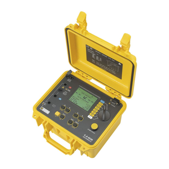
1. PRESENTATION 1.1. THE MEGOHMMETER The C.A 6549 megohmmeter is a portable unit, fitted into a rugged construction site casing with cover, operating on battery or line power. Its main functions are: „ automatic detection and measurement of voltage, frequency, input current, „... -
Page 5: Description
2. DESCRIPTION 2.1. HOUSING ➇ ➆ ➁ ➂ ➅ ➀ ➃ ➄ ➀ 3 4mm-dia. safety terminals identified as “+”, “G”, and “-”. ➁ Access to the fuse that protects terminal “G”. ➂ 8-way rotary switch: „ OFF switches instrument power off. „... -
Page 6: Keys
2.2. KEYS 8 keys each having a main function and a secondary function: Select the secondary function (indicated in yellow italics below each key). MODE Primary function: select the desired type of measurement, before an insulation measurement, or select the current range, during a measurement. - Page 7 Voltage generated dangerous, U > 120V External voltage present, U > 25 VRMS...
-
Page 8: Measurement Functions
3. MEASUREMENT FUNCTIONS 3.1. AC / DC VOLTAGE Turning the switch to an insulation position (position other than OFF or SET-UP) sets the instrument to automatic AC / DC voltage measurement. The voltage between the input terminals is measured at all times and indicated as RMS value on the display unit: Input Voltage. -
Page 9: Capacitance Measurement
Case 3 You select an insulation measurement with a test voltage that varies in steps: this STEP FUNCTION 1 is the “step function” mode. Min: 2300 V Max: 3900 V Position: Adjust. Step Test Run Time 08:38:30 You can choose among the three step functions (p and keys) you defined earlier Input voltage 1 V AC in SET-UP. -
Page 10: Special Functions
4. SPECIAL FUNCTIONS 4.1. MODE / PRINT KEY 4.1.1. PRIMARY FUNCTION BEFORE THE MEASUREMENT The primary function of the MODE key is very important: it is used before the measurement to define the course of the measurement. This key is inactive in the “Adjust. Step” and SET-UP positions. Pressing the MODE key gives access to the list of possible measurement modes. - Page 11 „ TIMED RUN + DD: MODE Total Run Time 02:30:00 This mode is identical to the previous one except that 1 minute after the end of the Manual Stop measurement the instrument calculates and displays the DD term. Manual Stop + DD The measurement duration is therefore: duration of timed run + 1 minute.
- Page 12 What are the DAR (Dielectric Absorption Ratio) and the PI (Polarization Index)? It is useful to calculate insulation quality ratios in addition to the quantitative insulation resistance value, because they can be used to eliminate the influence of certain parameters likely to invalidate the “absolute” insulation measurement. The most important of these parameters are: temperature and relative humidity, with which insulation resistance varies according to a quasi-exponential law.
-
Page 13: Display / Graph Key
4.1.3. SECONDARY FUNCTION The PRINT secondary function is described in § 6.3 (Printing of measured values). 4.2. DISPLAY / GRAPH KEY 4.2.1. PRIMARY FUNCTION DISPLAY This key is used to browse through the various accessible screens containing all information available before, during or after the measurement. - Page 14 After the measurement 0.1 V 234.5 MΩ FIXED VOLTAGE 500 V 0.0 Hz 507 V 224.6 pA 24.6 pA Elapsed Time 01:02:43 DAR (30s/60s) 2.64 Input voltage 0.1 V AC PI (1.0m/10m) 1.05 Frequency 0.0 Hz Capacitance 320 nF 1000 Input current 24.6 pA Date: 24.06.2008...
- Page 15 After the measurement 0.1 V 234.5 MΩ FIXED VOLTAGE 500 V 0.0 Hz 507 V 224.6 pA 24.6 pA Elapsed Time 00:22:43 DAR (30s/60s) 2.24 Input voltage 0.1 V AC PI (1.0m/10m) 1.56 Frequency 0.0 Hz Capacitance 220 nF 1000 Input current 24.6 pA DD current...
- Page 16 Available information: First screen Press on DISPLAY Insulation resistance Insulation resistance Measured voltage Measured voltage Measured current Measured current Remaining test duration Remaining test duration Resistance bargraph DAR, PI, capacitance After the measurement 0.1 V 234.5 MΩ ADJUSTABLE VOLTAGE 2 2300 V 2307 V 24.6 pA...
- Page 17 During the measurement 234.5 MΩ 234.5 MΩ 2307 V 2307 V 24.6 pA 24.6 pA Remaining Time 00:09:43 Remaining Time 00:09:43 DAR (30s/60s) PI (1.0m/10m) kΩ MΩ TΩ GΩ Capacitance 10 100 DD current --- pA Available information: First screen Press on DISPLAY Insulation resistance Insulation resistance...
- Page 18 Available information: First screen Press on DISPLAY Selected test voltage Input voltage Programmed test duration Frequency Input voltage Input current (DC only) Frequency Voltage bargraph Input current (DC only) Date, time During the measurement 234.5 MΩ 234.5 MΩ 5007 V 24.6 pA 5007 V 24.6 pA...
-
Page 19: T° Key
4.2.2. GRAPH SECONDARY FUNCTION This function is used to display the insulation resistance versus measurement time curve after a time-limited measurement (Timed Run or Timed Run + DD). This curve is plotted from the samples recorded during the measurement. The p, , u and keys can be used to move along the curve to display the exact values of each sample. -
Page 20: Smooth Key
4.4. / SMOOTH KEY The SMOOTH secondary function activates / deactivates an insulation measurement digital filter. It affects only the display (which is smoothed), not the measurements. This function is useful if the insulation values displayed are very unstable. The filter is calculated as follows: RSMOOTH = RSMOOTH + (R –... - Page 21 Timed Run (h:m): duration of test in "Timed run" mode. „ Default value Range 00: 10 (h:m) 00: 01 … 49: 59 (h:m) Sample Time (m:s): time interval between samples recorded in Timed Run mode for plotting R(t). „ Default value Range 00: 10 (m:s) 00: 05 …...
- Page 22 Temperature Unit: selection of temperature unit. „ Default value Range °C °C or °F Default Probe Temperature: measurement temperature. „ Default value Range 23 °C -15°C … +75°C Rc Reference Temperature: reference temperature to which the measurement result must be referred. „...
- Page 23 Date (d.m.y): current date or setting of date. „ Europe dd.mm.yyyy mm.dd.yyyy Time (h:m): current time or setting of time. „ 4.5.2. MEMORY ERASURE In SET-UP, select Clear memory. „ To erase the content of one or more specific OBJ: TEST numbers Select Select Data Sets to Clear by pressing u.
-
Page 24: List Of Coded Errors
„ Select at least 3 measurements using the p, , u or . SET-UP „ ∆T is calculated and recorded automatically once 3 stored measurements have ∆T Calculation fot R/2 23.7°C Obj. Test Res. Volt. Temp. been selected, and updated as more measurements are selected. 47 99 228.5 MΩ... -
Page 25: Procedure
5. PROCEDURE 5.1. COURSE OF MEASUREMENTS „ Start up the instrument by setting the switch to the position corresponding to the measurement to be made. The instrument can measure insulation values from 10 kΩ to 10 TΩ, depending on the test voltage selected-from 40 to 5100 V The screen displays: the battery symbol and battery charge condition, „... -
Page 26: Step Function Mode (Adj. Step)
b) Example of a cable (reduction of surface leakage effects) Braid Insulator External insulator Guard Cable Core Unless the step function mode is selected (Adj. Step), select the measurement mode to be used (Manual Stop, Manual Stop „ + DD, Timed Run, Timed Run + DD, DAR or PI) by pressing the MODE key (see § 4.1) A press on START/STOP triggers the measurement. - Page 27 Procedure: SET-UP „ In the SET-UP menu, select Set Step Function 1, 2 or 3. Instr.Nr. 700016 SW Version 1.8 PI (m/m) 1.0/10 Example: here, step function n°3. Set Step Function 1 Set Step Function 2 Set Step Function 3 Temperature Unit Celsius Defaut Probe Temperature...
-
Page 28: Memory / Rs 232
6. MEMORY / RS 232 6.1. RS 232 CHARACTERISTICS „ The baud rate can be set to 300, 600, 1200, 2400, 4800, 9600, or Parallel for printing on parallel printers via the optional serial / parallel adapter. This adjustment is performed in the SET-UP menu (see § 4.5) „... -
Page 29: Printing Measured Values (Print Key)
Timed Run test, the list of recorded samples. „ To stop printing, turn the rotary switch. Depending on the measurement performed, the following forms are obtained. „ All measurements except step function measurements: CHAUVIN ARNOUX C.A 6549 Instrument number: 700 016 Company: ..........Address: ...................... - Page 30 43.5 GOhm …etc Date of next test: ../../..Remarks: ......................Operator: ..........Signature: ..........„ Step function measurement: CHAUVIN ARNOUX C.A 6549 Instrument number: 700 016 Company: ..........Address: ......................Tel.: ............Fax: ............Email: ............ Description: ..........
- Page 31 The printing of each group of data is reduced to the main results. Depending on the measurements performed, the following models are obtained. „ All measurements except step function measurements: CHAUVIN ARNOUX C.A 6549 Instrument number: 700 016 Company: ..........
- Page 32 110 nF …etc Date of next test: ../../..Remarks: ......................Operator: ..........Signature: ..........„ Step function measurement: CHAUVIN ARNOUX C.A 6549 Instrument number: 700 016 Company: ..........Address: ......................Tel.: ............Fax: ............Email: ............ Description: ..........
- Page 33 „ Select “--- / Parallel” for the Baud Rate setting in SET-UP. „ Press PRINT. ATTENTION: This adapter is designed to be used only with the C.A 6543, C.A 6547, and C.A 6549 and is unsuitable for any other application.
-
Page 34: Specifications
7. SPECIFICATIONS 7.1. REFERENCE CONDITIONS Influence quantities Reference values Temperature 23 ± 3 °C Relative humidity 45 to 55 % RH Supply voltage 9 to 12 V Frequency range DC and 15.3 to 65 Hz Capacitance in parallel on resistance 0 µF Electric field Magnetic field... - Page 35 „ Maximum acceptable AC voltage: (1.1 + dISt) x Un + 60 V „ Measurement ranges: 500 V : 10 kΩ ... 1.999 TΩ 1000 V : 10 kΩ ... 3.999 TΩ 2500 V : 10 kΩ ... 9.99 TΩ 5000 V : 10 kΩ...
- Page 36 „ Typical curves, test voltage versus load Range 500 V MΩ 0,01 Range 1000 V 1200 1000 MΩ 0,01 Range 2500 V 3000 2500 2000 1500 1000 MΩ 0,01 Range 5000 V 6000 5000 4000 3000 2000 1000 MΩ 0,01 „...
-
Page 37: Power Supply
„ Calculation of the DD term Specified range 0.02 … 50.00 Resolution 0.01 Accuracy ± 10% + 1 ct „ Capacitance measurement (after discharge of tested element) Specified measurement range 0.005 … 9.999 µF 10.00 … 49.99 µF Resolution 1 nF 10 nF Accuracy ±... -
Page 38: Compliance With International Standards
7.6. COMPLIANCE WITH INTERNATIONAL STANDARDS „ Electrical safety as per: IEC 61010-1, IEC 61557 „ Double insulation „ Pollution level: 2 „ Measurement category: III „ Maximum voltage relative to earth: 1000 V 7.6.1. ELECTROMAGNETIC COMPATIBILITY Emissions and immunity in an industrial setting compliant with EN 61326-1. 7.6.2. -
Page 39: Maintenance
This instrument should be checked at least once a year. For checking and calibration, contact one of our accredited metrology laboratories (information and contact details available on request), at our Chauvin Arnoux subsidiary or the branch in your country. 8.3. REPAIR... -
Page 40: Warranty
9. WARRANTY Except as otherwise stated, our warranty is valid for twelve months starting from the date on which the equipment was sold. Extract from our General Conditions of Sale provided on request. The warranty does not apply in the following cases: „... -
Page 41: To Order
10. TO ORDER C.A 6549 Megohmmeter ............................P01139703 Delivered with bag containing: „ 2 x 3-m safety leads, fitted with a HV plug and a HV alligator clip (red and blue) „ 1 x 3-m guarded safety lead, fitted with a HV rear pick up plug and a HV alligator clip (black) „... - Page 42 Tel: 01 61 61 9 61-0 - Fax: 01 61 61 9 61-61 Tel: (01) 890 425 - Fax: (01) 890 424 SCANDINAVIA - CA Mätsystem AB USA - Chauvin Arnoux Inc - d.b.a AEMC Instruments Sjöflygvägen 35 - SE 18304 TÄBY 200 Foxborough Blvd. - Foxborough - MA 02035...
Need help?
Do you have a question about the C.A 6549 and is the answer not in the manual?
Questions and answers