Table of Contents
Advertisement
Advertisement
Table of Contents

Related Manuals for Chauvin Arnoux C.A 6165


Summary of Contents for Chauvin Arnoux C.A 6165
- Page 1 GB - User’s manual GB - User’s manual C.A 6165 Appliance multitester...
- Page 2 About the user’s manual This Instruction manual contains detailed information on the C.A 6165, its key features, functionalities and use. It is intended for technically qualified personnel responsible for the product and its use. Please note that LCD screenshots in this document may differ from the actual instrument screens in details due...
-
Page 3: Table Of Contents
Contents General description ............................6 Warnings and notes ........................... 6 1.1.1 Safety warnings ............................. 6 1.1.2 Warnings related to safety of measurement functions ................6 1.1.3 Markings on the instrument ........................7 Standards applied ............................7 Erection and operation of electrical test equipment ..................... 8 Instrument set and accessories ........................ - Page 4 Discharging time ............................. 117 10.12 General data............................117 Appendix A - Structure objects in C.A 6165 ......................119 Appendix B - Profile Notes ............................. 120 Appendix C - Print labels and write / read RFID / NFC tags ................. 121 PAT tag format ............................
- Page 5 ® E.3.1 Auto Sequence steps ........................128 E.3.2 Single tests ............................128 E.3.3 Flow commands ..........................129 E.3.4 Number of measurement steps ......................129 Creating / modifying an Auto Sequence® ....................129 Description of flow commands ........................ 130 Custom Inspections programming ......................135 E.6.1 Creating and editing Custom Inspections ..................
-
Page 6: General Description
1.1.1 Safety warnings In order to reach high level of operator safety while carrying out various measurements using the C.A 6165 instrument, as well as to keep the test equipment undamaged, it is necessary to consider the following general warnings: ... -
Page 7: Markings On The Instrument
This equipment should be recycled as electronic waste. 1.2 Standards applied The C.A 6165 instrument is manufactured and tested according to the following regulations, listed below. Electromagnetic compatibility (EMC) IEC 61326-1 Electrical equipment for measurement, control and laboratory use - EMC requirements –... -
Page 8: Erection And Operation Of Electrical Test Equipment
Functionality IEC 60335 Household and similar electrical appliances IEC 60950 Information technology equipment – Safety IEC 61439 Low-voltage switchgear and controlgear assemblies IEC 61010 Safety requirements for electrical equipment for measurement, control, and laboratory use IEC 60598 Safety of lighting equipment VDE 0701-702 Inspection after repair, modification of electrical appliances –... -
Page 9: Instrument Set And Accessories
2 Instrument set and accessories 2.1 Standard set of the instrument Instrument C.A 6165 Bag for accessories HV test probes 2 m, 2 pcs Continuity test lead set 2.5 m, 2 pcs Continuity test lead red 1.5 m / 2.5 mm ... -
Page 10: Instrument Description
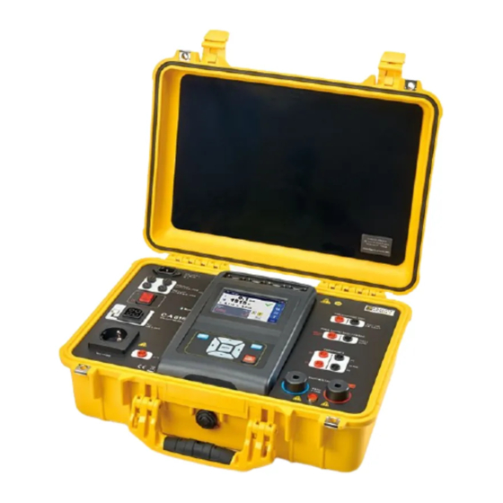
3 Instrument description 3.1 Front panel C.A 6165 Figure 3.1: Front panel Mains supply connector F1, F2 fuses (F 5 A / 250 V) F3, F4 fuses (T 16 A / 250 V) On / Off switch Test connections TC1 for external test adapters... -
Page 11: Instrument Operation
4 Instrument operation The C.A 6165 can be manipulated via a keypad or touch screen. 4.1 General meaning of keys Cursor keys are used to: select appropriate option Enter key is used to: confirm selected option start and stop measurements... -
Page 12: Safety Checks
4.3 Safety checks At start up and during operation the instrument performs various safety checks to ensure safety and to prevent any damage. These safety pre-tests are checking for: Correct input mains voltage Presence of input PE connection, ... - Page 13 In pre-test an external voltage between C1/P1 and C2/P2 terminals was detected. The measurement was cancelled. Press OK to continue. In pre-test a too high external voltage was detected between P and PE terminals. The measurement was cancelled. Press OK to continue.
- Page 14 The instrument is overheated. The measurement can’t be carried out until the icon disappears. Press OK to continue. The device under test should be switched on (to ensure that the complete circuit is tested). Test voltage in Insulation resistance measurement is too low. Measurement result is scaled to 110 V.
-
Page 15: Instrument Main Menu
4.5 Instrument main menu From the instrument Main Menu different main operation menus can be selected. Figure 4.1: Main menu Options Single Tests Menu with single tests, see chapter 6 Single tests. ® Auto Sequences Menu with customized test sequences, see chapter 7 Auto Sequences®. Memory Organizer Menu for working with and documentation of test data, see chapter 5 Memory Organizer. -
Page 16: General Settings
4.6 General settings In the General Settings menu general parameters and settings of the instrument can be viewed or set. Figure 4.2: Setup menu Options in General Settings menu Language Instrument language selection Date / Time Instruments Date and time. Workspace Manager Manipulation with project files. -
Page 17: Language
About Instrument info. 4.6.1 Language In this menu the language of the instrument can be set. Figure 4.3: Select language menu 4.6.2 Date and time In this menu date and time of the instrument can be set. Figure 4.4: Setting data and time menu 4.6.3 Profiles Refer to Chapter 4.7 Instrument profiles for more information. - Page 18 The user accounts can be managed by the administrator. User account pasword consists of an up to 4 digit number. Individual users can change their passwords. The administrator password consists of an up to 15 characters. Factory set administrator password is ADMIN. If the password is forgotten the second administrator password can be used.
- Page 19 Enter the Administrator password through on-screen keyboard and confirm Account manager screen is opened as presented on Figure 4.7. 4.6.6.2 C hanging us er pas s word, s igning out After user completed Sign in procedure, User profile menu screen is presented. Same screen is presented if signed in user selects User accounts from General Settings menu.
- Page 20 Wrong entry is reported by message. Confirm message, clear wrong password and repeat first step. Second step: enter new user password and confirm entry. Password change is confirmed with short message appearance. 4.6.6.3 Managing ac c ounts To access Account manager menu, Administrator should be signed in, see Chapter 4.6.6.1 Signing in for details. Administrator can set sign in requirement, change Administrator password and edit user accounts.
- Page 21 Options User sign in is not required. User sign in is required. Presented setting requires sign in, when instrument is switched on. Sign in could also be set to required on every restart of instrument. Change Administrator password. Alphanumerical keyboard appears on the screen. First step: enter current Administrator password and confirm entry.
- Page 22 4.6.6.4 E dit us er ac c ounts Administrator can add new user and set his password, change user existing password, delete user account and delete all user accounts. Edit accounts screen is accessed by selecting Edit account icon from Account manager options screen, see Chapter 4.6.6.3 Managing accounts.
-
Page 23: Change Password For Hv Functions
Warning message selection options: • YES: confirmation of deletion, all user accounts will be deleted • NO: interrupts procedure and return to Edit accounts menu User selected (user is highlighted Options Set password For selected user, password is set, numerical keyboard appears on the screen. -
Page 24: Settings
Notes: Default password is 0000. An empty entry disables the password. If password is lost, entry 4648 resets password to default. 4.6.8 Settings In this menu different general parameters can be set. Figure 4.10: Settings menu Setting options: Option Description Touch screen... -
Page 25: Devices
Ethernet setting options: Option Available selection Description Obtain an IP [AUTOMATICALLY, When the manual mode is chosen, the user must MANUAL] provide the correct network settings. Otherwise the instrument is automatically assigned an IP address from the local network using the DHCP protocol. IP address XXX.XXX.XXX.XXX Displays the instrument’s IP address. -
Page 26: Initial Settings
Writing devices Type Sets appropriate writing device (Serial printer, Bluetooth printer, RFID writer). Port Sets/views communication port of selected writing device. Bluetooth device name Goes to menu for pairing with selected Bluetooth device. Bluetooth dongle Initializes Bluetooth Dongle. Print labels Selects label form size. -
Page 27: About
4.6.11 About In this menu instrument data (name, serial number, version and date of calibration) can be viewed. Figure 4.13: Instrument info screen 4.7 Instrument profiles In this menu the instrument profile can be selected from the available ones. Figure 4.14: Instrument profile menu The instrument uses different specific system and measuring settings in regard to the scope of work or country it is used. -
Page 28: Workspace Manager
The Workspace Manager is intended to manage with different Workspaces and Exports stored on the microSD card. 4.8.1 Workspaces and Exports The works with C.A 6165 can be organized with help of Workspaces and Exports. Exports and Workspaces contain all relevant data (measurements, parameters, limits, structure objects) of an individual work. - Page 29 Options List of Workspaces. Displays a list of Exports. Adds a new Workspace. Refer to chapter 4.8.2.3 Adding a new Workspace for more information. List of Exports. Displays a list of Workspaces. 4.8.2.1 Operations with W orks pac es Only one Workspace can be opened in the instrument at the same time. The Workspace selected in the Workspace Manager will be opened in the Memory Organizer.
- Page 30 4.8.2.2 Operations with E xports Figure 4.18: Workspace manager Exports menu Options Deletes the selected Export. Refer to chapter 4.8.2.5 Deleting a Workspace / Export for more information. Imports a new Workspace from Export. Refer to chapter 4.8.2.6 Importing a Workspace for more information. 4.8.2.3 A dding a new Works pac e ...
- Page 31 After confirmation a new Workspace is added to the list of workspaces. 4.8.2.4 Opening a Works pac e Workspace can be selected from a list in Workspace manager screen. Opens a Workspace in Workspace manager. The opened Workspace is marked with a blue dot. The previously opened Workspace will close automatically.
- Page 32 Before deleting the selected Workspace / Export the user is asked for confirmation. Workspace / Export is deleted from the Workspace / Export list. 4.8.2.6 Importing a W orks pac e Select an Export file to be imported from Workspace manager Export list.
- Page 33 4.8.2.7 E xporting a W orks pac e Select a Workspace from Workspace manager list to be exported to an Export file. Enters option for Export. Before exporting the selected Workspace the user is asked for confirmation. Workspace is exported to Export file and is added to the list of Exports.
-
Page 34: Auto Sequence
4.9 Auto Sequence groups ® ® The Auto Sequences in C.A 6165 are organized in Auto Sequence groups stored in folders on the microSD memory card. Folders are located in Root\__MOS__\AT on the microSD card. ® Figure 4.19: Organization of Auto Sequence groups on microSD card ®... - Page 35 4.9.1.2 S elec ting a group of A uto S equenc es ® ® A group of Auto Sequences should be selected ® first from the list of Auto Sequence groups. Enters option for selecting a highlighted group. ®...
-
Page 36: Memory Organizer
Memory Organizer is a tool for storing and working with test data. 5.1 Memory Organizer menu The data is organized in a tree structure with Structure objects and Measurements. C.A 6165 has a fixed three level structure. The hierarchy of Structure objects in the tree is shown on Figure 5.1. -
Page 37: Measurement Statuses
Figure 5.2: Example of a Tree menu 5.1.1 Measurement statuses Each measurement has: a status (Pass or Fail or no status) a name results limits and parameters ® A measurement can be a Single test or an Auto Sequence test. -
Page 38: Structure Objects
Structure object a comment or a file attached Structure objects supported in C.A 6165 are described in Appendix A - Structure objects in C.A 6165. Figure 5.3: Structure object in tree menu 5.1.2.1 Meas urement s tatus indic ation under the S truc ture objec t Overall status of measurements under each structure element / sub-element can be seen without spreading tree menu. -
Page 39: Selecting An Active Workspace In Memory Organizer
Note: There is no status indication if all measurement results under each structure element / sub-element have passed or if there is an empty structure element / sub-element (without measurements). 5.1.3 Selecting an active Workspace in Memory Organizer Memory Organizer and Workspace Manager are interconnected so an active Workspace can be selected also in the Memory Organizer menu. -
Page 40: Adding Nodes In Memory Organizer
5.1.4 Adding Nodes in Memory Organizer Structural Elements (Nodes) are used to ease organization of data in the Memory Organizer. One Node is a must; others are optional and can be created or deleted freely. Procedure Press the active Workspace in Memory ... - Page 41 Figure 5.7: A measurement is selected in the Tree menu Options Views results of measurement. The instrument goes to the measurement memory screen. Refer to chapters 6.1.1.5 Single test ® memory screen and 7.2.4 Auto Sequence memory screen for more information. Starts a new measurement.
- Page 42 5.1.5.2 Operations on S truc ture objec ts The structure object must be selected first. Figure 5.8: A structure object is selected in the tree menu Options Starts a new measurement. ® First type of measurement (Single test or Auto Sequence ) should be selected.
- Page 43 Deletes a Structure object. Selected Structure object and sub-elements can be deleted. User is asked for confirmation before the deleting. Refer to chapter 5.1.5.11 Delete a Structure object for more information. Renames a Structure object. Selected Structure object can be renamed via keypad. Refer to chapter 5.1.5.13 Rename a Structure object for more information.
- Page 44 5.1.5.4 A dd a new S truc ture Objec t This menu is intended to add new structure objects in the tree menu. A new structure object can be selected and then added in the tree menu. Add Structure Figure 5.10: Add a new Structure Object menu The type of Structure object to be added can be selected from dropdown menu.
- Page 45 Adds the selected structure object and its parameters in the tree menu. Returns to the tree menu without changes. 5.1.5.5 A dd a new meas urement In this menu new empty measurements can be set and then added in the structure tree. The type of measurement, measurement function and its parameters are first selected and then added under the selected Structure object.
- Page 46 Add a new empty measurement. Adds the measurement under the selected Structure object in the tree menu. Returns to the structure tree menu without changes. 5.1.5.6 C lone a S truc ture objec t In this menu selected structure object can be copied (cloned) to same level in the structure tree. Cloned structure object have same name as original.
- Page 47 Cloning is cancelled. No changes in the Structure tree. The new structure object is displayed. 5.1.5.7 C lone a meas urement By using this function a selected empty or finished measurement can be copied (cloned) as an empty measurement to the same level in the structure tree.
- Page 48 Select Copy option from control panel. Copy Select location where structure element should be copied. Select Paste option from control panel. Paste The Paste structure object menu is displayed. Before copying it can be set which sub-elements of the selected structure object will be copied too.
- Page 49 Attachments of selected structure object will be copied too. Structure objects in sub-levels of selected structure object will be copied too. Measurements in selected structure object and sub-levels will be copied too. 5.1.5.10 C opy & P as te a meas urement In this menu selected measurement can be copied to any allowed location in the structure tree.
- Page 50 5.1.5.11 Delete a S truc ture objec t In this menu selected Structure object can be deleted. Procedure Select the structure object to be deleted. Select Delete option from control panel. Delete A confirmation window will appear. ...
- Page 51 A confirmation window will appear. Selected measurement is deleted. Returns to the tree menu without changes. 5.1.5.13 R ename a S truc ture objec t In this menu selected Structure object can be renamed. Procedure Select the structure object to be renamed. ...
- Page 52 5.1.5.14 R ec all and R etes t s elec ted meas urement Procedure Select the measurement to be recalled. Select Recall results in Control panel. Measurement is recalled. Parameters and limits can be viewed but cannot be edited.
-
Page 53: Searching In Memory Organizer
Select Run in Control panel to retest the measurement. Results / sub-results after re-run of recalled measurement. Select Save results in Control panel. Retested measurement is saved under same structure object as original one. Refreshed memory structure with the new performed measurement is displayed. - Page 54 The parameters that can be searched for are displayed in the Search setup menu. Name and status are referred to all structure objects. If searching by status, instrument will display all structure objects that include one or more measurements with searched status.
- Page 55 Figure 5.13: Search results screen – Page view Options Next page. Previous page. Note: Search result page consist of up to 50 results. Figure 5.14: Search results screen with structure object selected Options Goes to selected location in Memory Organizer. View / edit parameters and attachments.
- Page 56 Views comment. The instrument displays comment attached to the selected Structure object.
-
Page 57: Single Tests
6 Single tests 6.1 Selection of single tests Single tests can be selected in the Main single test menu or in Memory Organizer’s main and submenus. In Single test main menu there are four modes for selecting single tests. Options A single test can be selected from a list of all single tests. - Page 58 For the selected group a submenu with all single tests that belongs to the selected group is displayed. Cross selector This selection mode is the fastest way for working with the keypad. Groups of single tests are organized in a row. For the selected group all single tests are displayed and accessible with up/down keys.
-
Page 59: Single Test Screens
6.1.1 Single test screens In the Single test screens measuring results, sub-results, limits and parameters of the measurement are displayed. In addition on-line statuses, warnings and other information are displayed. Name of function Main result Options Subresult Parameters (white) and Statuses, info, warnings limits (red) Figure 6.1: Single test screen organisation... - Page 60 6.1.1.2 S etting parameters and limits of s ingle tes ts Figure 6.3: Screens in menu for setting Single test parameters and limits Options Selects parameter (white) or limit (red). Selects value of parameter or limit. In case of many (multiple pages of) parameters or limits: The scroll bar on the right side of screen can be used With right / left keys it can be jumped page up / page down Some of limits can be user defined.
- Page 61 6.1.1.3 S ingle tes t s c reen during tes t Figure 6.4: Single test screen (during measurement) Options (during test) Stops the single test measurement. Proceeds to the next step of the measurement (if measurement consists of more steps). Aborts measurements.
- Page 62 Saving under the last selected Structure object will be offered by default. The user can select another Structure object or create a new Structure object. By pressing key in Memory organizer menu the measurement is saved under selected location. An empty measurement was selected in structure tree and started: The result(s) will be added to the measurement.
-
Page 63: Single Test (Inspection) Screens
6.1.2 Single test (inspection) screens Visual and Functional inspections can be treated as a special class of tests. Items to be visually or functionally checked are displayed. In addition on-line statuses and other information are displayed. Figure 6.7: Inspection screen organisation 6.1.2.1 S ingle tes t (ins pec tion) s tart s c reen Figure 6.8: Inspection start screen... - Page 64 6.1.2.2 S ingle tes t (Ins pec tion) s c reen during tes t Figure 6.9: Inspection screen (during inspection) Options (during test) Selects item Applies a pass status to the selected item or group of items. Applies a fail status to the selected item or group of items. Clears status in selected item or group of items Applies a checked status to the selected item or group of items.
- Page 65 the fail status has highest priority. A fail status for any item will result in a fail status in all parent items and an overall fail result. if there is no fail status in child items the parent item will get a status only if all child items have a status. Pass status has priority over checked status.
-
Page 66: Help Screens
6.1.2.4 S ingle tes t (ins pec tion) memory s c reen Figure 6.11: Inspection memory screen Options Retest Starts inspection with cleared statuses. Enters view mode. 6.1.3 Help screens Help screens contain diagrams for proper connection of the instrument. Figure 6.12: Examples of help screens Options Goes to previous / next help screen. -
Page 67: Single Test Measurements
6.2 Single test measurements 6.2.1 Visual inspections Figure 6.13: Visual inspection menu Test circuit Figure 6.14: Visual inspection test circuit Visual inspection procedure Select the appropriate Visual inspection. Start the inspection. Perform the visual inspection of the appliance / equipment. ... -
Page 68: Continuity
6.2.2 Continuity Figure 6.16: Continuity test menu Test results / sub-results R ....Resistance ΔU………..Voltage drop scaled to 10 A Test parameters Output connections Output [4-wire, P-PE] Test current I out [0.2 A, 4 A, 10 A, 25 A] Duration Duration [Off, 2 s ... - Page 69 Figure 6.18: Measurement of Continuity P/S - PE Continuity measurement procedure Select the Continuity function. Set test parameters / limits. Connect test leads to C1, P1, P2 and C2 terminals on the instrument (4 wire), or connect test lead to P/S terminal (2 wire measurement P/S –...
- Page 70 6.2.2.1 C ompens ation of tes t leads res is tanc e This chapter describes how to compensate the test leads resistance in Continuity (Output = P/S – PE) function. Compensation can be carried out to eliminate the influence of test leads resistance and the internal resistances of the instrument on the measured resistance.
-
Page 71: Hv Ac
6.2.3 HV AC IMPORTANT SAFETY NOTE Refer to chapter 1.1 Warnings and notes for more information regarding safe use of the instrument. Figure 6.22: HV AC test menu Test results / sub-results I ....test current U ....measured a.c. test voltage Ir .... -
Page 72: Hv Dc
HV AC measurement procedure Select the HV AC function. Set test parameters / limits. Connect HV test leads to HV(~,+) and HV(~,-) terminals on the instrument. Connect HV test leads to device under test. Start measurement. ... - Page 73 Test limits High limit (I) H limit [0.05 mA ... 10.0 mA ] Low limit (I) L limit [Off, 0.05 mA ... 10.0 mA] Test circuit Figure 6.26: HV DC measurement HV DC measurement procedure Select the HV DC function. ...
-
Page 74: Hv Ac Programmable
6.2.5 HV AC programmable IMPORTANT SAFETY NOTE Refer to chapter 1.1 Warnings and notes for more information regarding safe use of the instrument. In the HV AC programmable test the time dependency of high voltage can be set according to diagram on Figure 6.28. Figure 6.28: Voltage / time diagram of the HV AC programmable test Figure 6.29: HV AC programmable test menu Test results / sub-results... - Page 75 Test circuit Figure 6.30: HV AC programmable test HV AC programmable test procedure Select the HV AC programmable function. Set test parameters / limits. Connect HV test leads to HV(~,+) and HV(~,-) terminals on the instrument. Connect HV test leads to device under test.
-
Page 76: Hv Dc Programmable
6.2.6 HV DC programmable IMPORTANT SAFETY NOTE Refer to chapter 1.1 Warnings and notes for more information regarding safe use of the instrument. In the HV DC programmable test the time dependency of high voltage can be set according to diagram on Figure 6.28. Figure 6.32: HV DC programmable test menu Test results / sub-results U .... - Page 77 Test circuit Figure 6.33: HV DC programmable test HV DC programmable test procedure Select the HV DC programmable function. Set test parameters / limits. Connect HV test leads to HV(~,+) and HV(~,-) terminals on the instrument. Connect HV test leads to device under test.
-
Page 78: Insulation Resistance (Riso, Riso-S)
6.2.7 Insulation resistance (Riso, Riso-S) Figure 6.35: Insulation resistance test menus Test results / sub-results Riso ....Insulation resistance Riso-S ..Insulation resistance-S Um ....Test voltage Test parameters Nominal test voltage Uiso [50 V, 100 V, 250 V, 500 V, 1000 V] Duration Duration [Off, 2 s ... - Page 79 Figure 6.37: Measurement of insulation resistance (Socket LN - PE) Figure 6.38: Measurement of Riso, Riso-S (socket) RISO measurement procedure Select the Riso function. Set test parameters / limits. Connect test leads to ISO(+), ISO(-) terminals on the instrument, then connect test leads to device under test, ...
-
Page 80: Sub-Leakage (Isub, Isub-S)
Figure 6.39: Examples of Insulation resistance measurement results Note: When P/S probe is connected during the Riso measurement, then the current through it is also considered. 6.2.8 Sub-leakage (Isub, Isub-S) Figure 6.40: Sub Leakage test menus Test results / sub-results Isub .... - Page 81 Test circuits Figure 6.41: Measurement of Sub-leakage (SUB1, SUB2) Figure 6.42: Measurement of Sub-leakage (socket LN-PE) Figure 6.43: Measurement of Sub-leakage, Sub-leakage-S (socket) Sub-leakage measurement procedure Select the Sub-leakage function. Set test parameters / limits. Connect test leads to SUB1,SUB2 terminals on the instrument, then connect test leads to device under test, or ...
-
Page 82: Differential Leakage
Save results (optional). Figure 6.44: Examples of Sub-leakage measurement results Note: When P/S probe is connected during the Sub-leakage measurement, then the current through it is also considered. 6.2.9 Differential Leakage Figure 6.45: Differential Leakage test menu Test results / sub-results Idiff .... -
Page 83: Ipe Leakage
Test circuit Figure 6.46: Measurement of Differential Leakage current Differential Leakage measurement procedure Select the Differential Leakage function. Set test parameters / limits. Connect device under test to mains test socket and optionally to P/S terminal. Start measurement. - Page 84 Figure 6.48: Ipe Leakage test menu Test results / sub-results Ipe ....PE current P ....Power Test parameters Duration Duration [Off, 2 s ... 180 s] Change status Change [YES, NO] YES: The instrument measures leakage current in two sequential steps with delay* in between.
-
Page 85: Touch Leakage
Test circuit Figure 6.49: Measurement of Ipe Leakage current Ipe Leakage measurement procedure Select the Ipe Leakage function. Set test parameters / limits. Connect device under test to mains test socket. Start measurement. Measurement can be stopped manually or by timer. ... - Page 86 Test results / sub-results Itou ....Touch Leakage current P ....Power Test parameters Duration Duration [Off, 2 s ... 180 s] Change status Change [YES, NO] YES: The instrument measures leakage current in two sequential steps with delay* in between.
-
Page 87: Power
6.2.12 Power Figure 6.54: Power measurement menu Test results / sub-results P ....Active power S ....Apparent power Q ....Reactive power PF ....Power factor THDu .... Total harmonic distortion – voltage THDi ..... Total harmonic distortion – current Cos Φ... -
Page 88: Leak's & Power
Power measurement procedure Select the Power function. Set test parameters / limits. Connect device under test to mains test socket. Start measurement. Measurement can be stopped manually or by timer. Save results (optional). Figure 6.56: Examples of Power measurement results 6.2.13 Leak's &... - Page 89 Test parameters Duration Duration [Off, 2 s ... 180 s] Change status Change [YES, NO] YES: The instrument measures leakage current in two sequential steps with delay* in between. The phase voltage is firstly applied to the right live output of the mains test socket and secondly to the left live output of the mains test socket.
-
Page 90: Discharging Time
Figure 6.59: Examples of Leak’s & Power measurement results 6.2.14 Discharging Time Figure 6.60: Discharging Time test menu Test results / sub-results t ....Discharging time Up ....Peak voltage of supply during the test Test parameters Limit voltage Limit U [34 V, 60 V, 120 V] Output connections Output [External, Socket] Test mode... - Page 91 (1) peak voltage (4) Ulim (2) voltage at disconnection time (5) moment of disconnection (3) calculated voltage value (6) discharging time Figure 6.61: Measuring principle (external) Test circuit (Output = External) Figure 6.62: Discharging Time test (Output = External) Discharging Time test procedure (Output = External) ...
- Page 92 Figure 6.63: Examples of Discharging Time measurement results (Output = External) Measuring principle (Output = Socket) The measuring principle of the Discharging time function is as following: Phase The DEVICE UNDER TEST is connected to the mains test socket.The instrument monitors the mains voltage and internally stores the peak voltage value.
-
Page 93: Functional Inspections
Figure 6.65: Examples of Discharging Time measurement results (Output = Socket) 6.2.15 Functional inspections Figure 6.66: Functional inspection start menu (left) and menu during inspection (right) Test parameters (optional) For the optional Power measurement test the parameters and limits are the same as set in the Power single test, see chapter 6.2.12 Power. - Page 94 Figure 6.68 Examples of Functional Inspection results...
-
Page 95: Auto Sequences
® 7 Auto Sequences ® Preprogrammed sequences of measurements can be carried out in Auto Sequences menu. The sequence of measurements, their parameters and flow of the sequence can be programmed. The ® results of an Auto Sequence can be stored in the memory together with all related information. ®... -
Page 96: Searching In Auto Sequences Menu
® New Auto Sequence group is selected and all ® folders, sub-folders and Auto Sequences within that group are displayed on the screen. ® 7.1.2 Searching in Auto Sequences menu ® ® In Auto Sequence menu it is possible to search for Auto Sequences on base of their Name or Short code. - Page 97 ® Searches through the active Auto Sequence group according to the set filters. The results are shown in the Search results screen presented on Figure 7.1 and Figure 7.2. Figure 7.1: Search results screen Page view Options Next page. Previous page.
-
Page 98: Structure Organization Of Auto Sequence
® Starts the selected Auto Sequence ® 7.1.3 Structure organization of Auto Sequence group ® ® The Auto Sequences to be carried out can be selected from the active group in Main Auto Sequences menu. This ® ® menu can be organized in a structural manner with folders, sub-folders and Auto Sequences . -
Page 99: Organization Of Auto Sequence
® 7.2 Organization of Auto Sequence tests ® An Auto Sequence test is divided into three phases: ® Before starting the first test the Auto Sequence view menu is shown (unless it was started ® directly from the Main Auto Sequence menu). - Page 100 7.2.1.2 A uto S equenc e ® view menu (meas urement is s elec ted) ® Figure 7.5: Auto Sequence view menu – measurement selected Options Selects single test. Opens menu for changing parameters and limits of selected measurements. Refer to chapter 6.1.1.2 Setting parameters and limits of single tests for more information how to change measurement parameters and limits.
-
Page 101: Step By Step Excecution Of Auto Sequences
Sets operation mode for multiple points. For more information see chapter 7.2.1.4 Managing multiple points. 7.2.1.3 Indic ation of L oops The attached ‘x3’ at the end of single test name indicates that a loop of single tests is programmed. This means that the marked single test will be carried out as many times as the number behind the ‘x’... -
Page 102: Auto Sequence
® Figure 7.7: Auto Sequence – example of a finished measurement with options for proceeding ® Options (during execution of an Auto Sequence Proceeds to next step in the test sequence. Repeats the measurement if multiple points execution is selected. Displayed result of a single test will be stored. - Page 103 ® Figure 7.8: Auto Sequence result screen Options Start Test ® Starts a new Auto Sequence View results of individual measurements. ® The instrument goes to menu for viewing details of the Auto Sequence , see Figure 7.9. ® Adds comment to the Auto Sequence .
- Page 104 Write RFID / NFC tag and Save Auto Sequence® results simultaneously. Option is available if Devices parameter Auto save is set to On write, see chapter 4.6.9 Devices for more information. Note: Options menu content depends on Devices settings menu. If no writing device is set, than ‘Print label’ and ‘Write RFID’ icons are hidden.
-
Page 105: Auto Sequence Memory Screen
® 7.2.4 Auto Sequence memory screen ® In Auto Sequence memory screen details of the auto test can be viewed, labels can be printed and a new Auto ® Sequence can be restarted. ® Figure 7.10: Auto Sequence memory screen Options ®... -
Page 106: Maintenance
Unauthorized person is not allowed to open the C.A 6165 instrument. There are no user replaceable parts inside the instrument. 8.4 Cleaning Use a soft, slightly moistened cloth with soap water or alcohol to clean the surface of C.A 6165 instrument. Leave the instrument to dry totally before using it. Notes: ... -
Page 107: Communications
Some Android applications automatically carry out the setup of a Bluetooth connection. It is preferred to use this option if it exists. This option is supported by Chauvin Arnoux's Android applications. If this option is not supported by the selected Android application then configure a Bluetooth link via Android device’s Bluetooth configuration tool. -
Page 108: Bluetooth Communication With Printers And Scanners
9.3 Bluetooth communication with printers and scanners The C.A 6165 instrument can communicate with supported Bluetooth printers and scanners. Contact Chauvin Arnoux or your distributor which external devices and functionalities are supported. See Chapter 4.6.9 Devices for details how to set the external Bluetooth devices. -
Page 109: Inputs
9.7 INPUTs The DB9 connector INPUTs is intended for connection of external control signals. Figure 9.2: INPUT connector - pin layout Legend: Description Type EXTERNAL OK KEY Input for Remote control pedal mode Input low: < 1 V d.c. against earth IN_2 External input 2 Input high: >... -
Page 110: Outputs
9.8 OUTPUTs Via the DB9 connector OUTPUT four control signals for external devices are provided. Figure 9.3: OUTPUT connector - pin layout Legend: Pins Description Type OUT_1 Control output 1 NO relay, Umax: 24V, Imax: 1.5 A Output low: open contact Output high:... -
Page 111: Technical Specifications
10 Technical specifications 10.1 HV AC, HV AC programmable Voltage a.c. Range Resolution Accuracy ±(3 % of reading) 0 V ... 1999 V ±(3 % of reading) 2.00 kV ... 5.99 kV 10 V Current a.c. (apparent) Range Resolution Accuracy ±(3 % of reading + 3 D) 0.0 mA ... -
Page 112: Continuity
10.3 Continuity Continuity Range Resolution Accuracy 0.00 Ω ... 19.99 Ω 0.01 Ω ±(2 % of reading + 2 D) 20.0 Ω ... 99.9 Ω 0.1 Ω ± 3 % of reading 100.0 Ω ... 199.9 Ω 0.1 Ω ± 5 % of reading 200 Ω... -
Page 113: Substitute Leakage Current, Substitute Leakage Current - S
Operating range (acc. to EN 61557-2) ....... 0.08 MΩ ... 199.9 MΩ Nominal voltages Un (d.c.) ......... 50 V, 100 V, 250 V, 500 V, 1000V (- 0 %, + 10 %) Short circuit current ............ max. 2.0 mA Test terminals Function Connections Mains test socket (LN), ISO(+) ↔... -
Page 114: Pe Leakage Current
10.7 PE leakage current PE leakage current Range Resolution Accuracy ±(3 % of reading + 3 D) 0.00 mA ... 19.99 mA 0.01 mA Power (active) Range Resolution Accuracy ±(5 % of reading + 5 D) 0.00 W…19.99 W 0.01 W ±... -
Page 115: Leak's & Power
Power (reactive) Range Resolution Accuracy ±(5 % of reading + 10 D) 0.00 VAr …19.99 VAr 0.01 VAr ± 5 % of reading 20.0 VAr …199.9 VAr 0.1 VAr ± 5 % of reading 200 VAr ... 1999 VAr 1 VAr ±... - Page 116 Power (reactive) Range Resolution Accuracy ±(5 % of reading + 10 D) 0.00 VAr …19.99 VAr 0.01 VAr ± 5 % of reading 20.0 VAr …199.9 VAr 0.1 VAr ± 5 % of reading 200 VAr ... 1999 VAr 1 VAr ±...
-
Page 117: Discharging Time
10.11 Discharging time Discharging time Range Resolution Accuracy ±(5 % of reading + 2 D) 0.0 s ... 9.9 s 0.1 s Peak voltage Range Resolution Accuracy ±(5 % of reading + 3 D) 0 V ... 550 V Operating range (acc. to EN 61557-14) ......0.8 s ... 9.9 s High limits ................. - Page 118 Communication Memory ................depends on microSD card size RS232 interfaces .............. two DB9 ports USB 2.0 ................Standard USB Type B Bluetooth ................Class 2 Ethernet ................Dynamic IP (DHCP) Static IP (manual) I/Os Inputs ................DB9 connector (24 V max) Outputs ................
-
Page 119: Appendix A - Structure Objects In C.a 6165
Appendix A - Structure objects in C.A 6165 Structure elements used in Memory Organizer are instrument’s Profile dependent. Symbol Default name Description Node Node Project Project Location Location Element Universal element Appliance Appliance (basic description) Appliance FD Appliance (full description) -
Page 120: Appendix B - Profile Notes
Appendix B - Profile Notes There are no specific profile notes for C.A 6165 . -
Page 121: Appendix C - Print Labels And Write / Read Rfid / Nfc Tags
The instrument supports RFID / NFC reader / writer device, tag type supported is NTAG216. Please check with Chauvin Arnoux or distributor which printers and labels are supported in your instrument. C.1 PAT tag format It is intended for tagging of individual appliance with Auto Sequence® test data. To start printing, Auto Sequence®... - Page 122 Following table describes tag content arrangement and its data for supported label form size. Form size Tag content Data W x H arrangement (mm) Text Parent object name, Test code, Object ID, test or retest date, status, user 50 x 25.5 Parent object name, Test code, Object ID, test date, test period, Auto Sequence®...
-
Page 123: Appendix D - Default List Of Auto Sequences
Appendix D - ® Default list of Auto Sequences Pre-programmed DEMO Auto Sequences® Name Description ® This Auto Sequence is just for demonstration of manipulation of Auto DEMO_1 ® Sequence operation. ® This Auto Sequence is just for demonstration of manipulation of Auto DEMO_2 ®... -
Page 124: Appendix E - Programming Of Auto Sequences
Appendix E - ® Programming of Auto Sequences on MT Link ® ® ® The Auto Sequence Editor is a part of the MT Link software. In Auto Sequence Editor, Auto Sequences can be pre- programmed and organized in groups, before uploaded to the instrument. ®... -
Page 125: Managing Of Auto Sequence Groups
® An Auto Sequence begins with Name, Description and Image, followed by the first step (Header), one or more measuring steps and ends with the last step (Result). By inserting appropriate Single tests and Flow commands ® and setting their parameters, arbitrary Auto Sequences can be created. - Page 126 ® ® Operation options on Files and Auto Sequence Group are available from menu bar at the top of Auto Sequence editor workspace. File operation options: ® Opens a file (Auto Sequence Group). ® Creates a new file (Auto Sequence Group).
-
Page 127: Search Within Selected Auto Sequence
Double click on the object name allows it name edit: ® ® Auto Sequence name: Edit Auto Sequence name DOUBLE CLICK Folder name: Edit folder name ® Drag and drop of the selected Auto Sequence or Folder / Subfolder moves it to a new location: DRAG &... -
Page 128: Elements Of An Auto Sequence
® Figure E.7: Example of Search result within Auto Sequence group ® E.3 Elements of an Auto Sequence ® E.3.1 Auto Sequence steps ® There are three kinds of Auto Sequence steps. Header The Header step is empty by default. Flow commands can be added to the Header step. -
Page 129: Flow Commands
E.3.3 Flow commands Flow commands are used to control the flow of measurements. Refer to chapter E.5 Description of flow commands for more information. E.3.4 Number of measurement steps Often the same measurement step has to be performed on multiple points on the device under test. It is possible to set how many times a Measurement step will be repeated. -
Page 130: Description Of Flow Commands
E.5 Description of flow commands Double click on inserted Flow Command opens menu window, where text or picture can be entered, external signalling and external commands can be activated and parameters can be set. Flow commands Operation after end of test and Results screen are entered by default, others are user selectable from Flow Commands menu. - Page 131 Wait input mode Reads input condition on pins IN_2, IN_3, IN_4 and IN_5 on INPUT port. Input must be high to proceed with the Auto ® Sequence Parameters State – enables Wait input mode; active INPUT from Input pins menu Off –...
- Page 132 On – enables External TEST / OK key mode (INPUT pin 5 is active) Off – disables External TEST / OK key mode No notifications mode Instrument skips pre-test warnings (see C.A 6165 User Manual, chapter 4.4 Symbols and messages for more information). Parameters State On –...
- Page 133 Parameters State On – enables automatic settings of tickers in Visual and Functual tests. Off – disables automatic settings of tickers in Visual and Functional tests. Flow Protocol This flow command controls commands for communication with external device for the control of the flow of Auto ®...
- Page 134 Result screen ® This flow command controls the proceeding after the Auto Sequence has ended. Parameters ® Auto Save Auto Sequence results are stored in the momentary workspace. A new Node with the month and year will be created. Under the Node Auto ®...
-
Page 135: Custom Inspections Programming
E.6 Custom Inspections programming Arbitrary set of tasks dedicated to specific user defined Inspections can be programmed with application of Custom Inspection Editor Tool, accessible from Auto Sequence® Editor workspace. Custom Inspections are stored in dedicated file *.indf with user defined name. For application of Custom Inspections as a single test within Auto Sequence® group, appropriate file containing specific Custom Inspection should be opened first. - Page 136 Remove selected custom inspection. To select inspection, click to the inspection Name field. To remove it, select icon from editor main menu. Before removal, user is asked to confirm deletion. Edit Name and Scope of Inspection Inspection Name edit: Click to the Inspection Name field to start editing it. Drag cursor, with left mouse button pressed, to select letters and words.
-
Page 137: Applying Custom Inspections
Edit Name and Type of Item task Edit Name of Item task: Click to the Item task Name field to start editing it. Drag cursor, with left mouse button pressed, to select letters and words. Position cursor and double-click to select word of the name. Actions could be performed with keyboard also.
Need help?
Do you have a question about the C.A 6165 and is the answer not in the manual?
Questions and answers