Table of Contents
Advertisement
Quick Links
Advertisement
Table of Contents

Subscribe to Our Youtube Channel
Related Manuals for Chauvin Arnoux TERCA 3


Summary of Contents for Chauvin Arnoux TERCA 3
- Page 1 EN - User’s manual C.A 6470N Earth and resistivity tester...
- Page 2 Thank you for purchasing a C.A 6470N earth and resistivity tester. To obtain the best service from your instrument: „ read these operating instructions carefully, „ comply with the precautions for use. WARNING, risk of DANGER! The operator must refer to these instructions whenever this danger symbol appears. Equipment protected by double insulation.
-
Page 3: Table Of Contents
CONTENTS 1. START-UP ....................................4 1.1. Unpacking ..................................4 1.2. Characteristics label ............................... 4 1.3. Accessories ..................................5 1.4. Replacement parts ................................. 5 1.5. Charging the battery ............................... 6 2. PRESENTATION OF THE DEVICE ............................7 2.1. Functions of the device ..............................8 2.2. -
Page 4: Start-Up
1. START-UP 1.1. UNPACKING C.A 6472 Ohmmètre de terre F R A N Ç A I S Mémento HX0056-Z One line power adapter + 2-pole cable to recharge the battery. Data export software + an optical/USB communication cord. User manual in 5 languages, on CD-ROM. -
Page 5: Accessories
Optical/USB communication cable Prestige carrying bag Miscellaneous „ Replacement parts for Earth & resistivity kit: see the list enclosed with the standard kit or contact your Chauvin Arnoux agency or your approved dealer. For accessories and spare parts, visit our website:... -
Page 6: Charging The Battery
1.5. CHARGING THE BATTERY ± 100-240 V~ (±10%) > 110 Vac 800 mA < 240 Vac Ω 50/60 Hz 50 / 60 Hz ALARM Ω Ω AUTO Charging time: 3h30’ Start by fully charging the battery before the first use. The charging must be done between 0 and 40°C. After prolonged storage, the battery may be fully discharged. -
Page 7: Presentation Of The Device
2. PRESENTATION OF THE DEVICE... -
Page 8: Functions Of The Device
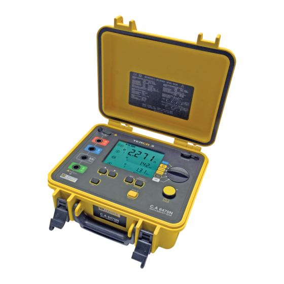
2.1. FUNCTIONS OF THE DEVICE The C.A 6470N earth tester is a complete portable measuring device intended for earth measurements and soil resistivity measure- ments. It is contained in a housing suitable for field use and supplied by a rechargeable battery with built-in charger. Measurement functions resistance, 2-wire or 4-wire, earth resistance, 3-point or 4-point... -
Page 9: Display Unit
2.3. DISPLAY UNIT ρ EARTH COUPLING 1 2 3 4 OK ± > < Ω Ω ALARM OBJ. TEST > < DC AC kΩft NOISE DISTANCEFREQUENCY SMOOTH > < REMOTE kΩft MEMMR CONFIG MANUALAUTO Fig. 1 DANGER symbol. Audible tone On. A flashing «>»... -
Page 10: Operating Principle
Rotating arrows indicate that a measurement is in progress. Indicates that the ALARM function is active. Indicates the distances d or/and A. Indicates which of terminals H, S, ES, and E are to be connected according to the measurement function chosen (fixed) or are missing (flashing). -
Page 11: Automatic Mode
3. AUTOMATIC MODE 3.1. RESISTANCE MEASUREMENT 3.1.1. 2-WIRE MEASUREMENT Connect the resistance to be measured between terminals H and E. It must not Set the switch to mΩ. be live. ± Ω ALARM Ω mΩ mΩ Ω AUTO Start the measurement by press- The device makes a meas- ing the START/STOP button. - Page 12 3.1.3. ALARM FUNCTION This function exists only for the 2-wire resistance measurement. By default, the visual alarm (the ALARM symbol flashes) and the audible alarm (the buzzer sounds for a few seconds) are triggered when R < 2Ω. This threshold can be changed using the SET- UP function.
- Page 13 3.1.4. 4-WIRE MEASUREMENT This measurement is used to improve the resolution (10x better than the 2-wire measurement) for weak resistance values; no compensation for the measurement leads is needed. The device must first be configured for the 4-wire measurement. Press the CONFIG key ...
-
Page 14: Earth Measurement
3.2. 3P EARTH MEASUREMENT This function is used to measure an earth resistance with 2 auxiliary electrodes. There are several measurement methods. We recommend the “62%” method. Plant electrodes H and S to form a straight line with the earth electrode. The distance be- tween electrode S and the earth electrode is 62% of the distance between electrode H and the earth electrode;... - Page 15 3.2.1 RECOMMENDATIONS FOR A RELIABLE MEASUREMENT „ Moving the auxiliary electrodes Move electrode S towards electrode H by a distance equal to 10% of d and make another measurement. Then move electrode S again by a distance equal to 10% of d, but towards the earth electrode. 52% d 62% d 72% d...
-
Page 16: Earth Measurement
3.3. 4P EARTH MEASUREMENT This function is suited to the measurement of very low earth resistances. It provides better resolution (10x better than 3P measure- ment) and there is no need to compensate for the resistance of the measurement leads. Place electrodes H and S at least 30m apart. -
Page 17: Measurement Of Soil Resistivity R
3.4. MEASUREMENT OF SOIL RESISTIVITY r To measure the resistivity of the soil, you can choose between the Wenner and Schlumberger methods. The difference between the two methods lies in the positioning of the electrodes. By default, the device selects the Wenner method, but if you want to vary the distance between the electrodes, use the Schlumberger method, which allows you to move only 2 measurement electrodes rather than 3. - Page 18 To select the hun- To select the tens. dreds (of metres). ρ ρ Ω Ω Ω Ω DISTANCE DISTANCE AUTO AUTO To m o d i f y t h e To select and modify the metres and tens.
- Page 19 To display the measurement parameters, press the DISPLAY key several times. The device displays the following quantities (see the glossary, §12): , d, U , U-Act (U and its frequency, U and its frequency). S-ES S-ES S-ES DISPLAY To measure the resistances of electrodes H, S, ES, and E, or if the resistance of the electrodes is too high (see §4), start the measurement by a long press of the START/STOP button.
- Page 20 ρ To display the measurement parameters, press the DISPLAY key several times. Ω The device displays the following quantities (see the glossary, §12): , d, A, U , U-Act (U and its frequency, U and its fre- Ω S-ES S-ES S-ES quency).
-
Page 21: Error Reporting
4. ERROR REPORTING 4.1. ELECTRODE RESISTANCE TOO HIGH This can happen in a 3- or 4-pole earth measurement, or a resistivity measurement. This message is displayed when the measurement was triggered by a short press on the START/STOP button and the resistances of the electrodes are too high. - Page 22 After the measurement has started there are indicators of when: „ Values R and/or R are too high, „ Measurement current I is too low, „ The instability of the measurement is large. Those conditions that may give uncertain results are indicated on the display of the unit as follows: Function Triggering threshold Indication on the display unit...
-
Page 23: Measurements In Manual Mode
5. MEASUREMENTS IN MANUAL MODE It is possible to modify the parameters of all of the measurement functions described for the automatic mode in §3 by changing to manual mode. To access the manual mode, press the CONFIG key. The CONFIG symbol is displayed and the AUTO symbol flashes. By pressing key, you can change to manual mode (display of the MANUAL symbol). -
Page 24: Manual Settings For The Resistance Measurement
5.3. MANUAL SETTINGS FOR THE RESISTANCE MEASUREMENT In manual mode, successive presses on the CONFIG key let you access the following parameters and change them using the key „ Symbols of terminals H and E flash (2-point measurement) H S ES E flash (4-point measurement) „... -
Page 25: Manual Settings For The 4P Earth Measurement
After switching from EARTH to EARTH COUPLING, using the CONFIG and keys, proceed as follows: „ If you want to eliminate the resistance of the measurement leads, you can use lead compensation (2nd + START) before start- ing the actual coupling measurement (see §3.1.2). „... -
Page 26: Manual Settings For The Soil Resistivity Measurement
5.6. MANUAL SETTINGS FOR THE SOIL RESISTIVITY MEASUREMENT In the manual mode, successive presses on the CONFIG key let you access the following parameters and change them using the key: flashes (Wenner method) Switching to r (Schlumberger method) „ r „... -
Page 27: Memory Function
6. MEMORY FUNCTION The device has a total of 512 memory locations. Each of these locations is defined by an object number (OBJ) from 01 to 99 and by a TEST number from 01 to 99. During resistivity measurements (Wenner or Schlumberger methods), several measurement results are recorded at the same memory location, with the distance between electrodes as the third addressing criterion. -
Page 28: Retrieval Of Stored Results
For soil resistivity and potential measurements, if you make several measurements with different distances d, you can store them under the same OBJ:TEST number, with the distance as third addressing criterion. ρ Ω OBJ. TEST It will subsequently be possible to overwrite values already stored with new ones having the same distance d, or even to add new results having other values for the distance d provided that all of the other measurement parameters are identical. -
Page 29: Erasure Of The Memory
6.3. ERASURE OF THE MEMORY There are two ways to erase the internal memory of the tester: 6.3.1. COMPLETE ERASURE Press the MEM key to display the number of Set the switch to SET-UP. memory spaces available. SET-UP SET-UP Press the MEM key again. - Page 30 To erase the selected record. Press the MEM key. In the case of a record having a third addressing criterion, only the one displayed will be erased. (long press) OBJ. TEST > 2s SWEEP To exit without erasing (short press).
-
Page 31: Configuration (Setup)
7. CONFIGURATION (SETUP) Set the switch to SET-UP. The device prompts you to press a key with the following message: SET-UP SET-UP 7.1. PRESS THE CONFIG KEY The CONFIG key is used to set the date, the time, and the data transfer rate. It is also used to reset the device to the factory set- tings, but the date, the time, and any stored measurement results will be kept. -
Page 32: Press The Mem Key
You can choose the bus address of the device The buzzer can be activated (On) (for communication with a PC) between 1 and or deactivated (OFF). 247. DISPLAY DISPLAY 7.3. PRESS THE MEM KEY By pressing the MEM key, you can display the level of occupancy of the memory of the device and possibly erase all records (see §6.3.1). -
Page 33: Error Messages
8. ERROR MESSAGES When started up, the C.A 6470N device automatically performs a self-test. If a fault appears during this self-test or during a meas- urement, the device displays a message in the form Err XX. There are 3 categories of errors: Errors 6, 7 and 11 „... -
Page 34: Connection To A Pc And Analysis Software
9. CONNECTION TO A PC AND ANALYSIS SOFTWARE You will find more detailed information about connection to a PC, remote control of the tester by a PC, reading measurement results stored in the device, and the modification of certain data in the memory in the documentation of DataView software for earth testers. -
Page 35: Specifications And Technical Characteristics
10. SPECIFICATIONS AND TECHNICAL CHARACTERISTICS 10.1. REFERENCE CONDITIONS Quantities of influence Reference values Temperature 20 ± 3 °C Relative humidity 45 to 55 % RH Supply voltage 9 to 11,2 V Frequency band of the input signal 0 to 440 Hz Capacitance in parallel with the input resistance 0 µF Electric field... - Page 36 „ Functional voltage measurements The values of U and U , used for DC and AC voltage resistance measurements, are called “functional voltages” and are S-ES measured by the instrument. In all AC voltage functions, it is the fundamental frequency of the voltage created by the test signal that is measured. The operating uncertainty of a functional voltage measurement may be greater than that indicated for an AC resistance measure- ment because, during the calibration of the instrument, the frequency characteristics of the voltage channel are matched to those of the current channel.
- Page 37 4-wire mΩ measurements Measurement range 0.020 - 9.999 Ω 10.00 - 99.99 Ω 100.0 - 999.9 Ω 1.000 - 9.999 kΩ 10.00 - 99.99 kΩ Resolution 0.001 Ω 0.01 Ω 0.1 Ω 1 Ω 10 Ω Intrinsic error ± (2% + 2 pt) Operating error ±...
- Page 38 Operating conditions: R < 3 x R = 32 V Operating error for R Values for R and R Frequency (Hz) ≥ 0 Ω, Rs ≤ 3 kΩ 41 - 513 ± (3% + 2 pt) ) / R < 3000 >...
-
Page 39: Power Supply
10.3. POWER SUPPLY The instrument is powered by a rechargeable 9.6 V 3.5 Ah minimum NiMH battery pack. This has many advantages: „ long life with small size and weight, „ the possibility of recharging your battery rapidly, „ a very small memory effect: you can recharge your battery rapidly, even if it is not fully discharged, without reducing its capacity, „... -
Page 40: Environmental Conditions
10.4. ENVIRONMENTAL CONDITIONS Use indoors or outdoors. Range of use 0°C to +45°C and 0% to 90% RH Specified operating range 0°C to +35°C and 0% to 75% RH Storage (without battery) -40°C to +70°C and 0% to 90% RH Altitude <... -
Page 41: Terms And Definitions
11. TERMS AND DEFINITIONS This section recalls the definitions of a few of the terms used in the context of earth measurements: Active earth measurement Measurement made using a current from the internal voltage generator of the device, between terminals H and E. Auxiliary earth electrode (H) An auxiliary earth contact through which the measurement current flows. -
Page 42: Glossary
12. GLOSSARY This glossary lists the terms and abbreviations used on the device and its digital display unit. 3 poles: earth resistance measurement with 2 auxiliary electrodes (3P). 4 poles: 4-wire measurement of low earth resistance using 2 auxiliary electrodes (4P). coupling coefficient of earth R with earth R coupling coefficient of earth R... -
Page 43: Maintenance
13. MAINTENANCE Except for the fuse and the battery, the instrument contains no parts that can be replaced by personnel who have not been specially trained and accredited. Any unauthorized repair or replacement of a part by an “equivalent” may gravely impair safety. -
Page 44: Replacing The Battery
6. Place the body of the device in the housing, close the cover, and tighten the attachment screws. 13.3. REPLACING THE BATTERY The battery of this device is specific: it has precisely matched protection and safety elements. Replacement of the battery by a model other than the one specified may result in damage to equipment or bodily injury by explosion or fire. - Page 45 11. Slide the battery a short way out of its compartment, without forcing on the wires, and screw the two screws at the bottom of the compartment back in. Then put the battery back in its place. 12. Put the battery compartment cover back in place and tighten the screws. 13.
-
Page 46: Warranty
14. WARRANTY Except as otherwise stated, our warranty is valid for 24 months starting from the date on which the equipment was sold. Extract from our General Conditions of Sale, communicated on request. The warranty does not apply in the following cases: „... - Page 48 FRANCE INTERNATIONAL Chauvin Arnoux Group Chauvin Arnoux Group 190, rue Championnet Tél : +33 1 44 85 44 38 75876 PARIS Cedex 18 Fax : +33 1 46 27 95 69 Tél : +33 1 44 85 44 85 Our international contacts Fax : +33 1 46 27 73 89 info@chauvin-arnoux.com...
Need help?
Do you have a question about the TERCA 3 and is the answer not in the manual?
Questions and answers