Table of Contents
Advertisement
Advertisement
Table of Contents

Related Manuals for Chauvin Arnoux C.A 6115N


Summary of Contents for Chauvin Arnoux C.A 6115N
- Page 1 C.A 6115N INSTALLATION TESTER E N G L I S H User's manual...
-
Page 2: Safety Precautions
Category III meets with strict reliability and environmental requisites corresponding to permanent use on fixed industrial installations (see IEC 664-1). Do not use the C.A 6115N tester on installations exceeding 300 V in relation to earth. Use connection accessories of overvoltage category and service voltage greater than, or equal to, the measurement instrument (300 V Cat III). -
Page 3: Table Of Contents
4. GENERAL USE ..........................8 Automatic checks of measurement conditions ................ 8 Connecting the instrument ....................... 8 C.A 6115N Operating principle ....................9 Changing settings (thresholds …) ..................9 “SET UP” = General settings ....................10 Standby mode (Power down-Pd) ................... 11 Power up information ...................... -
Page 4: General Presentation
1. GENERAL PRESENTATION The C.A 6115N is a measurement instrument designed for testing the safety of electrical installations. Measurement functions: Voltage, frequency, current/leakage current, insulation resistance, RCD’s, earth resistance – selective earth resistance, fault voltage, loop impedance, short- circuit current, resistance/continuity, phase order, protective conductor testing,... - Page 5 Charge time: max. 120 Min. (fast charge) Number of measurements per charge: Min. of 1500 with use of maximum current (i.e. insulation measurements at 500 V) Dimensions: 295 mm x 230 mm x 108 mm (L x W x H) with cover; Weight: approx.
-
Page 6: Description Of The Instrument
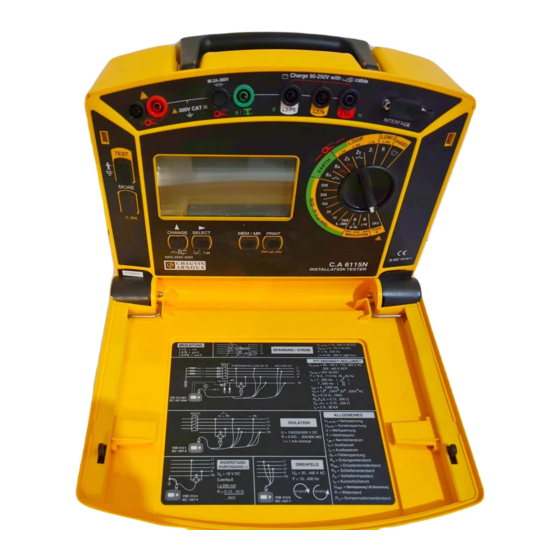
2. DESCRIPTION OF THE INSTRUMENT Rotating selector switch, used to select the required measurement function and to switch OFF the instrument. Charge indicator LED, comes on or flashes during automatic charging when the selector switch is on the “OFF/CHARGE” position and the instrument is plugged into the mains. Button used to start the test chosen using the selector switch. -
Page 7: Using For The First Time
Label with the technical specifications and wiring diagrams. 3. USING FOR THE FIRST TIME The C.A 6115N is fitted with NiMH rechargeable batteries that should be charged up before using the instrument for the first time. To do this, proceed as described in §9.2. -
Page 8: General Use
3. Start measurement using the “TEST” button. NOTE: Beginning with the version 2.8 of the C.A 6115N, there are two ways to start a measurement with the test button. A short press starts a normal measurement. A long press (> 2 sec. till the buzzer sounds) causes the instrument to measure the mean value out of 10 single measurements. -
Page 9: 6115N Operating Principle
(test leads not connected to the instrument, defective fuse…) or by some other disturbance. Start again. If you press on the “MEM / MR” button, the C.A 6115N switches to Saving mode to store the measurement made. See chapter 6.2. -
Page 10: Set Up" = General Settings
3. To save the changes, press the “MORE” button. 4.5 “SET UP” = General settings This mode makes it possible to adapt the general settings on the C.A 6115N to the specific needs of the operator, including: setting standby mode on/off, the buzzer, date, time, lead compensation, RS232 baud rate …... -
Page 11: Standby Mode (Power Down-Pd)
Means: 2.8 Software version 300 001 Instrument number 4.8 Remote control probe This probe plugs into the C.A 6115N’s RS232 socket. It is Croc-clips fitted with a 4 mm safety socket on its underside, making it Remote possible to connect one of the three test leads, L, N, or PE. -
Page 12: Measurements
Internal resistance : Approx. 400 kΩ Maximum overload : V max. = 500 V 5.1.3 Performing a measurement 1. Connect the C.A 6115N to the installation, as illustrated. 2. Select any position with the switch Check that the white point on the mains plug can be seen from above. -
Page 13: Checking The Protective Conductor Pe (Earth)
Interruption: Automatic marking and locking of the measurement, at a network voltage of 90 – 440 V ; 16 – 65 Hz Internal resistance: approx. 700 kΩ 5.2.3 Making a measurement 1. Connect the C.A 6115N to the installation, as illustrated opposite. 2. Select any position with the switch except phase order determination. -
Page 14: Measuring Voltage And Frequency
5.3 Measuring voltage and frequency 5.3.1 AC/DC voltage measurements - Technical specifications All measured values are calibrated for a sine wave. Measurement range Range Resolution Frequency range 95 … 440 V 0 … 500 V DC - AC 15.3 … 450 Hz Accuracy: ±... -
Page 15: Measuring Current And Leakage Current With A Clamp
5.3.3 Measuring voltage and frequency 1. Connect the instrument according to the diagram opposite. 2. Select any position with the switch 3. Read off all the measurements using the “MORE” button. 4. To save or print out voltages and frequencies, a live TEST (RCD, earth, loop, phase rotation) must be run with the TEST button;... - Page 16 Only connect clamps compliant with EN 61010 to these terminals, with safety leads such as those supplied optionally for the C.A 6115N. WARNING: No foreign voltage should be applied to the clamp inputs! Otherwise the protective fuse will blow and the input may be damaged! 5.4.3 Performing a measurement...
-
Page 17: Measuring Insulation Resistance
5.4.4 Error indications Display Meaning Comments Measured current too high, Measurement range exceeded wrong clamp (e.g. 100:1) or foreign voltage connected Frequency out of 45…450Hz Measurement not possible range or current too low Charge batteries Measurement not possible If the indication appears several Battery discharged times à... - Page 18 Measurement range Resolution Accuracy 5 kΩ …9.99 MΩ …600/300* MΩ 1 … 10 … 100 kΩ … 1 MΩ ± (6 % R + 1 ct) * only at 100 V, 250 V Measurement range of Resolution Accuracy DC voltage 1 …...
- Page 19 1. Connect the instrument as shown in the connection diagram. 2. Turn the selector switch to “INSULATION”, automatic L - N - PE or L-PE (2 poles) If using a measurement cable with 3 separate leads for a bipolar L-PE measurement, the N lead (yellow) that is not used should be connected to the PE lead (white).
-
Page 20: Rcd Testing
5.5.6 Error indications Display Meaning Comments Measurement not possible, Voltage > 20 V on the input, for example Voltage present on network voltage not cut measurement input Measured value greater than Resistance exceeding the measurement 600 MΩ (at 500V) or range, lead cut or badly connected 300 MΩ... - Page 21 Next, a non-tripping test of the RCD is carried out automatically. To do this, the network is charged throughout 50 periods (> 1000 ms) with 50% of I ∆N Depending on the user’s initial choice, the following test is either a “Ramp” test to obtain the exact RCD tripping current, or a “Pulse”...
- Page 22 Measurement range of tripping time (t Range Resolution Accuracy Ramp: 0...200 ms Pulse: 0...500 ms 0.1...7...500 ms 0.1 ms ± 2 ms Without tripping: 0...1000 ms (automatic warning if t > 200 ms) Measurement range of tripping current Resolution Accuracy 17 steps of 0.5 to 1.033 I between 6...1000 mA 3.33% of I...
- Page 23 Before and after method: This method makes it possible to trip an RCD even if another RCD of lower rating comes before it. If this is the case, connect the instrument to a phase before the RCD to be tested and connect the remaining test leads (neutral and earth) to the neutral after the RCD to be tested.
- Page 24 5.6.4 Error indications - Comments Display Meaning Comments Contact voltage cannot be measured, Earth resistance too high as it is above 100 V Test current setting may be WARNING: danger ! incorrect Leakage current in the installation + the test current <...
-
Page 25: Measuring Earth Resistance Ra (Za Since Software Version 2.8)
Furthermore, it is also possible to selectively measure a single earth among several, without having to disconnect the earth from the installation. A current clamp (optional) must be connected to the C.A 6115N (See also chapter 5.8). NOTE: unstable measurements, caused by heavy disturbances in the mains supply can be reduced by making a long press on the “TEST”... - Page 26 Measurement duration: 3 … 60 Periods, depending on the earth resistance and test current. Probe voltage measurement range Resolution Accuracy 1 …70 V 0.1 V ± (2 % of R. + 1 ct) NOTE: The inductive component of Za is measured within the values 0 ≤ Za ≤15 Ω. function (without tripping 30 mA RCD’s) : Measurement range Resolution (Ω)
- Page 27 5.7.2 Performing a measurement TT system > 20 m IT system > 20 m TN system > 20 m In this function, connection to the neutral is not necessary for “R ” measurement but is for "R ". For “R ”, you can connect the “neutral”...
- Page 28 TT system: This is the ideal diagram for quick and easy measurement of the ground earth: no earth connection to disconnect and just one extra earth testing rod to plant! IT system: It is also easy on a TT system but BEWARE: The supply transformer must be connected to the earth by an impedance.
-
Page 29: Measuring Loop Impedance : Short-Circuit Current / Fault Voltage /Earth
5.7.3 Error indications - Comments Display Meaning Comments Voltage less than 90 V Measurement not possible, Poor connection possible as the voltage is outside of the nominal range Voltage too high Measurement not possible, Frequency above 450 Hz frequency outside of the nominal range Frequency below 15.3 Hz The installation’s RCD... - Page 30 : short cut current , ZA: earth resitance (impedance) is accessible in C.A 6115N Version 2.8 combined with the Utility Software 3.2. In function Zs L-PE, the following measurements are possible depending on the connection of the inputs. The instrument automatically performs the different measurements (Application: TT or TN...
- Page 31 So that the fault voltage (earthing voltage at the nominal current of the RCD) is measured and displayed in position L - PE, the earth probe must be connected. If the earth probe and a current clamp are connected to the instrument, the selective earth measurement is also automatically carried out (position Zs SEL).
- Page 32 5.8.3 Performing a measurement In this function, connection to the neutral is only obligatory for "Z "measurement. For “Z ”, the “neutral” test lead can be connected to the earth and for “Z ”, it can be connected to a phase (phase- phase loop measurement).
- Page 33 2. Turn the selector switch to the LOOP “Z ” L-PE position for the earth loop impedance or “Z ” L-N for the network impedance. So that the fault voltage is automatically measured on the LOOP Z position, connect the earth probe to the instrument.
- Page 34 Maximum loop impedance authorised for different protective devices, according to table A1 of the DIN VDE 100 standard, part 610 (example). Low voltage fuse as per Circuit-breaker as per Circuit-breaker 220 V DIN standard VDE 0636 DIN standard VDE 0641 with characteristics with characteristic L 1), 2), 3)
- Page 35 5.8.4 Error indications Display Meaning Comments Voltage less than 90 V Connection may be defective Measurement not possible, as the voltage is outside the nominal range Voltage above 440 V Protective conductor Protective conductor defective possibly interrupted, Incorrectly connected or live. WARNING: Danger of electrocution! Frequency above 450 Hz Measurement not possible, as...
-
Page 36: Measuring Resistance / Testing Continuity
5.9 Measuring resistance / testing continuity This function enables resistance measurement up to 1999 Ω, with DC voltage and automatic polarity inversion. To take into account the resistance of the leads, it is possible to compensate for their resistance. Additionally, a maximum resistance threshold can be programmed, with an audible signal to confirm the measurement. - Page 37 5.9.4 Performing a measurement 1. Connect the C.A 6115N according to the suggested connection diagram with the cable with 3 separate leads. Connect lead L (white) the lead L (yellow). The measurement can be made between the earthing rod and the different points of the ground circuit: earth terminals on mains plugs, metal radiator housing or light fittings…...
-
Page 38: Determining Phase Order
5.10 Determining phase order This function is used to check the phase order on three-phase networks with voltages of 20 V to 440 V and frequencies of 15.3 … 450 Hz. The voltages L1 – L2 or L2 - L3 and L3 – L1 and the frequency are also indicated. -
Page 39: Measurement Lead Compensation
5.11 Measurement lead compensation This function is used to save the resistances of auxiliary accessories: test probes, croc-clips, leads, etc. before measuring. These resistance values are automatically deducted from measurements during all resistance ,R). Values up to 5 Ω can be compensated for. measurements (R The resistance of the original measurement cables supplied is compensated for during manufacturing and applies even when R... -
Page 40: Rs232 Interface / Memory
6. RS232 INTERFACE / MEMORY This instrument is equipped with an RS232 serial interface (SUB-D 9 poles) and memory capable of storing approximately 800 groups of values (a measurement + secondary measurements + context : voltage, current, frequency, date, time ….). The instrument has a real time clock for the date and time. The interface enables measured or saved values to be printed out or transferred to a computer with the C.A. -
Page 41: Saving / Calling Up Measured Values
Connection to a PC or to a parallel printer 9-pin connector to C.A 6115N 9-pin connector to PC 25-pin connector 25-pin connector to PC or serial-to-parallel adapter → → → → → → → → → → Necessary links DB9... - Page 42 6.2.1 Saving measured values (MEM) 1. Carry out the required measurement and wait for the measured value to come up on the display. Press on the “MEM/MR” button to call the save function. “MEM” flashes and the free memory save number following the last filled space is suggested, for example: The display of “FREE”...
-
Page 43: Printing Measured Values
4. Press the “MEM/MR” once more. The display goes back to voltage measurement. All the values stored in the memory are deleted. To verify this, press “MEM/MR”. This display indicates that the memory is empty. You can also easily delete values in memory with the optional PC software. WARNING: All the saved values are irreversibly deleted! 6.3 Printing measured values The instrument offers two possibilities for printing:... - Page 44 2. Printing documents (doc) Measurements that have not yet been saved or saved measurements can be printed out one after the other on a serial RS232 printer in A6 format, or on parallel A4 printers via an optional “serial-to- parallel” adapter. 6.3.1 Preparing the printout The settings below, defined in the SET-UP menu, are used to configure the default printing parameters.
-
Page 45: Saving Or Printing At Programmable Intervals
6.3.3 Printing saved values This function is used to print out saved values stored in the memory in “doc” format (measurements one after the other with the date, time etc…) or in “prt” format (measurement protocol = general summary table in A4 format). 1. -
Page 46: Serial-To-Parallel Adapter (Rs232 - Centronics) (Optional)
5. To start printing unsaved measurements (immediate printing), press PRINT after the measurement. 6. To start printing saved measurements, press the “PRINT” button (see § 6.3) in “Voltage measurement” mode. CAUTION: This adapter is exclusively designed to be used with the C.A 6115N and should not be used for any other purpose. -
Page 47: 6115 Utility Windows Software For Pc (Optional)
FOR PC (OPTIONAL) A Windows (3.11 or 95 or 98 or NT) run software package is available as an option for the C.A 6115N. This software enables the saved measurements to be read off, the setting of variables (date, time, limit values etc…), the establishment of test protocols and the creation of text files that can be read by... -
Page 48: Procedure
2) Plug the adapter unit into the outlet socket furthest away from the distribution board. 3) Select position A (L-E) on the adapter unit. 4) Make a low Ohms measurement with the C.A 6115N. This is the value of R1 + R2. 5) Disconnect the temporary link at the distribution board after the test. -
Page 49: Cleaning And Maintenance
10.2 Charging the battery 1. Connect the C.A 6115N to the mains supply (90-250 V AC 50 / 60 Hz) via the cable with a mains plug. 2. Turn the selector switch to the “OFF/CHARGE” position. -
Page 50: Storage
If the fuses blow, “- E -” is displayed. In this case, inspection of the C.A 6115N by a recognised service centre is necessary. 10.4 Storage If the C.A 6115N remains in storage or unused for a prolonged period of time, charge the batteries from time to time to avoid any damage. 10.5 Metrological check IIt is essential that all measuring instruments are regularly calibrated. -
Page 51: Ordering References
11. ORDERING REFERENCES C.A. 6115N (GB) Tester ........................P01.1454.12A Comes with a small shoulder bag containing a cable for measuring or charging with a schuko-type mains plug, a measurement cable with 3 separate leads, 3 test probes, 3 croc-clips, 1 green lead + test probe and the user’s manual in English. - Page 52 Green test probe ............................. P01.1019.20 30 m long green lead on reel (for earth measurements) ................P01.2951.28 T-shaped earth testing rod ........................P01.1018.29 Shoulder bag for the 2 measurement/charging cables ................P01.2980.32 PC RS232 DB9F-DB25F cable x2 + DB9M-DB9M adapter ..............P01.2951.72 RS232 DB9F-DB9M serial printer cable + DB9M-DB9M adapter ............
- Page 56 09 - 2001 Code 688 732 B00 - Ed. 2 Deutschland : CA GmbH - Straßburger Str. 34 - 77694 Kehl / Rhein - Tel : (07851) 99 26-0 - Fax : (07851) 99 26-60 España : CA Iberica - C/Roger de Flor N° 293 - 08025 Barcelona - Tel : (93) 459 08 11 - Fax : (93) 459 14 43 Italia : AMRA MTI - via Sant' Ambrogio, 23/25 - 20050 Bareggia Di Macherio (MI) - Tel : (039) 245 75 45 - Fax : (039) 481 561 Österreich : CA Ges.m.b.H - Slamastrasse 29 / 3 - 1230 Wien - Tel : (1) 61 61 9 61 - Fax : (1) 61 61 9 61 61 Schweiz : CA AG - Einsiedlerstrasse 535 - 8810 Horgen - Tel : (01) 727 75 55 - Fax : (01) 727 75 56...
Need help?
Do you have a question about the C.A 6115N and is the answer not in the manual?
Questions and answers