Table of Contents
Advertisement
Quick Links
Advertisement
Table of Contents

Subscribe to Our Youtube Channel
Related Manuals for Chauvin Arnoux C.A 6471


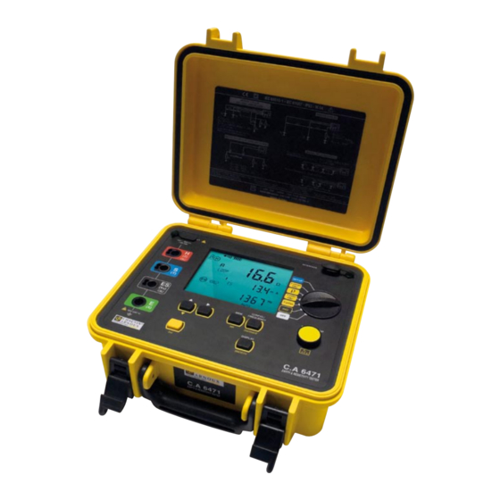
Summary of Contents for Chauvin Arnoux C.A 6471
- Page 1 C.A 6471 EARTH AND RESISTIVITY TESTER User's manual E N G L I S H...
- Page 2 Thank you for purchasing a C.A 6471 earth and resistivity tester. To obtain the best service from your unit: „ read these operating instructions carefully, „ comply with the precautions for use. WARNING, risk of DANGER! The operator must refer to these instructions whenever this danger symbol appears.
-
Page 3: Table Of Contents
CONTENTS 1. START-UP ....................................4 1.1. Unpacking ..................................4 1.2. Characteristics label ..............................4 1.3. Charging the battery ..............................5 2. PRESENTATION OF THE DEVICE ............................6 2.1. Functions of the device ..............................7 2.2. Keypad ................................... 7 2.3. Display unit ..................................8 2.4. -
Page 4: Start-Up
1. START-UP 1.1. UNPACKING C.A 6472 Ohmmètre de terre F R A N Ç A I S Mémento HX0056-Z One line power adapter + 2-pole cable to recharge the battery. Data export software + an optical/USB communication cord. User manual on CD-ROM (1 per language). -
Page 5: Charging The Battery
1.3. CHARGING THE BATTERY ± > 110 Vac < 240 Vac Ω 50 / 60 Hz ALARM Ω Ω AUTO Charging time: 3h30’ Start by fully charging the battery before the first use. The charging must be done between 0 and 40°C. After prolonged storage, the battery may be fully discharged. -
Page 6: Presentation Of The Device
2. PRESENTATION OF THE DEVICE... -
Page 7: Functions Of The Device
2.1. FUNCTIONS OF THE DEVICE The C.A 6471 earth tester is a complete portable measuring device intended for earth measurements and soil resistivity measure- ments. It is contained in a housing suitable for field use and supplied by a rechargeable battery with built-in charger. -
Page 8: Display Unit
2.3. DISPLAY UNIT ρ EARTH COUPLING 1 2 3 4 OK ± > < Ω Ω ALARM OBJ. TEST > < DC AC kΩft NOISE DISTANCEFREQUENCY SMOOTH > < REMOTE kΩft MEMMR CONFIG MANUALAUTO Fig. 1 DANGER symbol. Audible tone On. A flashing «>»... -
Page 9: Operating Principle
Display of the measured parameter (R, U, I). Rotating arrows indicate that a measurement is in progress. Indicates that the ALARM function is active. Indicates the distances d or/and A. Indicates that a clamp must be connected to terminal H (flashing) or is connected to it (steady). Indicates which of terminals H, S, ES, and E are to be connected according to the measurement function chosen (fixed) or are missing (flashing). -
Page 10: Automatic Mode
3. AUTOMATIC MODE 3.1. RESISTANCE MEASUREMENT 3.1.1. 2-WIRE MEASUREMENT Connect the resistance to be measured Set the switch to mΩ. between terminals H and E. It must not be live. ± Ω ALARM Ω mΩ mΩ Ω AUTO Start the measurement by press- The device makes a meas- ing the START/STOP button. - Page 11 3.1.3. ALARM FUNCTION This function exists only for the 2-wire resistance measurement. By default, the visual alarm (the ALARM symbol flashes) and the audible alarm (the buzzer sounds for a few seconds) are triggered when R < 2Ω. This threshold can be changed using the SET- UP function.
- Page 12 3.1.4. 4-WIRE MEASUREMENT This measurement is used to improve the resolution (10x better than the 2-wire measurement) for weak resistance values; no compensation for the measurement leads is needed. The device must first be configured for the 4-wire measurement. Press the CONFIG ...
-
Page 13: Earth Measurement
3.2. 3P EARTH MEASUREMENT This function is used to measure an earth resistance with 2 auxiliary electrodes. There are several measurement methods. We recommend the “62%” method. Plant electrodes H and S to form a straight line with the earth electrode. The distance Set the switch to “3 poles”. - Page 14 3.2.1 RECOMMENDATIONS FOR A RELIABLE MEASUREMENT „ Moving the auxiliary electrodes Move electrode S towards electrode H by a distance equal to 10% of d and make another measurement. Then move electrode S again by a distance equal to 10% of d, but towards the earth electrode. 52% d 62% d 72% d...
-
Page 15: Earth Measurement
3.3. 4P EARTH MEASUREMENT 3.3.1. MEASUREMENT WITHOUT CLAMP This function is suited to the measurement of very low earth resistances. It provides better resolution (10x better than 3P meas- urement) and there is no need to compensate for the resistance of the measurement leads. Set the switch to “4 poles”. - Page 16 20mm in diameter. Use only these two types of current clamp, which are specially designed to work with the C.A 6471 earth and resistivity tester. Place electrodes H and S at least 30m apart so that the potential wells that form around Set the switch to them do not intersect.
- Page 17 To measure the resistances of electrodes H and S, or if the resistance of the electrodes is too large (see §4), start the measurement with a long press of the START/STOP button. Ω > 2s kΩ kΩ START/STOP AUTO...
-
Page 18: Measurement Of Soil Resistivity R
3.4. MEASUREMENT OF SOIL RESISTIVITY r To measure the resistivity of the soil, you can choose between the Wenner and Schlumberger methods. The difference between the two methods lies in the positioning of the electrodes. By default, the device selects the Wenner method, but if you want to vary the distance between the electrodes, use the Schlumberger method, which allows you to move only 2 measurement elec- trodes rather than 3. - Page 19 To select the hun- To s e l e c t t h e ρ dreds (of metres). tens. ρ Ω Ω Ω Ω DISTANCE DISTANCE AUTO AUTO To m o d i f y t h e To select and modify the metres and tens.
- Page 20 To display the measurement parameters, press the DISPLAY key several times. The device displays the following quantities (see the glossary, §12): , d, U , U-Act (U and its frequency, U and its frequency). S-ES S-ES S-ES DISPLAY To measure the resistances of electrodes H, S, ES, and E, or if the resistance of the electrodes is too high (see §4), start the measurement by a long press of the START/STOP button.
- Page 21 ρ To display the measurement parameters, press the DISPLAY key several times. Ω The device displays the following quantities (see the glossary, §12): Ω , d, A, U , U-Act (U and its frequency, U and its fre- S-ES S-ES S-ES quency).
-
Page 22: Earth Measurements With 2 Clamps
LOOP Use only C182 or MN82 current clamps; they are specially designed to operate with the C.A 6471. Connect a clamp to terminal H and clamp the earth. Connect the other clamp to terminal Set the switch to 2 clamps. -
Page 23: Error Reporting
4. ERROR REPORTING 4.1. ELECTRODE RESISTANCE TOO HIGH This can happen in a 3- or 4-pole earth measurement, or a resistivity measurement. This message is displayed when the measurement was triggered by a short press on the START/STOP button and the resistances of the electrodes are too high. - Page 24 After the measurement has started there are indicators of when: „ Values R and/or R are too high, „ Measurement current I or I is too low, „ The instability of the measurement is large. Those conditions that may give uncertain results are indicated on the display of the unit as follows: Function Triggering threshold Indication on the display unit...
-
Page 25: Measurements In Manual Mode
5. MEASUREMENTS IN MANUAL MODE It is possible to modify the parameters of all of the measurement functions described for the automatic mode in §3 by changing to manual mode. To access the manual mode, press the CONFIG key. The CONFIG symbol is displayed and the AUTO symbol flashes. By press- ing the key, you can change to manual mode (display of the MANUAL symbol). -
Page 26: Manual Settings For The Resistance Measurement
5.3. MANUAL SETTINGS FOR THE RESISTANCE MEASUREMENT In manual mode, successive presses on the CONFIG key let you access the following parameters and change them using the „ Symbols of terminals H and E flash (2-point measurement) H S ES E flash (4-point measurement) „... -
Page 27: Manual Settings For The 4P Earth Measurement
After switching from EARTH to EARTH COUPLING, using the CONFIG and keys, proceed as follows: „ If you want to eliminate the resistance of the measurement leads, you can use lead compensation (2nd + START) before start- ing the actual coupling measurement (see §3.1.2). „... -
Page 28: Manual Settings For The Soil Resistivity Measurement
5.6. MANUAL SETTINGS FOR THE SOIL RESISTIVITY MEASUREMENT In the manual mode, successive presses on the CONFIG key let you access the following parameters and change them using key: „ r Switching to r flashes (Wenner method) (Schlumberger method) „... -
Page 29: Memory Function
6. MEMORY FUNCTION The device has a total of 512 memory locations. Each of these locations is defined by an object number (OBJ) from 01 to 99 and by a TEST number from 01 to 99. During resistivity measurements (Wenner or Schlumberger methods), several measurement results are recorded at the same memory location, with the distance between electrodes as the third addressing criterion. -
Page 30: Retrieval Of Stored Results
For soil resistivity and potential measurements, if you make several measurements with different distances d, you can store them under the same OBJ:TEST number, with the distance as third addressing criterion. ρ Ω OBJ. TEST It will subsequently be possible to overwrite values already stored with new ones having the same distance d, or even to add new results having other values for the distance d provided that all of the other measurement parameters are identical. -
Page 31: Erasure Of The Memory
6.3. ERASURE OF THE MEMORY There are two ways to erase the internal memory of the tester: 6.3.1. COMPLETE ERASURE Press the MEM key to display the number of Set the switch to SET-UP. memory spaces available. SET-UP SET-UP Press the MEM key again. - Page 32 To erase the selected record. Press the MEM key. In the case of a record having a third addressing criterion, only the one displayed will be erased. (long press) OBJ. TEST > 2s SWEEP To exit without erasing (short press).
-
Page 33: Configuration (Setup)
7. CONFIGURATION (SETUP) Set the switch to SET-UP. The device prompts you to press a key with the following message: SET-UP SET-UP 7.1. PRESS THE CONFIG KEY The CONFIG key is used to set the date, the time, and the data transfer rate. It is also used to reset the device to the factory settings, but the date, the time, and any stored measurement results will be kept. -
Page 34: Press The Mem Key
You can choose the bus address of the device The buzzer can be activated (On) (for communication with a PC) between 1 and or deactivated (OFF). 247. DISPLAY DISPLAY 7.3. PRESS THE MEM KEY By pressing the MEM key, you can display the level of occupancy of the memory of the device and possibly erase all records (see §6.3.1). -
Page 35: Error Messages
8. ERROR MESSAGES When started up, the C.A 6471 device automatically performs a self-test. If a fault appears during this self-test or during a meas- urement, the device displays a message in the form Err XX. There are 3 categories of errors: Errors 6, 7 and 11 „... -
Page 36: Connection To A Pc And Analysis Software
9. CONNECTION TO A PC AND ANALYSIS SOFTWARE You will find more detailed information about connection to a PC, remote control of the tester by a PC, reading measurement results stored in the device, and the modification of certain data in the memory in the documentation of DataView software for earth testers. -
Page 37: Specifications And Technical Characteristics
10. SPECIFICATIONS AND TECHNICAL CHARACTERISTICS 10.1. REFERENCE CONDITIONS Quantities of influence Reference values Temperature 20 ± 3 °C Relative humidity 45 to 55 % RH Supply voltage 9 to 11,2 V Frequency band of the input signal 0 to 440 Hz Capacitance in parallel with the input resistance 0 µF Electric field... - Page 38 ± (7% + 2 pt) (1): The C.A 6471 device cannot tell which clamp is connected to the instrument. In the case of the MN82 clamp, with currents > 10 A and frequencies < 100 Hz, there will therefore be no warning message. The user is responsible for ensuring observ- ance of the limits of use of the MN82 current clamp.
- Page 39 Frequency band DC and 41 – 513 Hz 537 – 5078 Hz Intrinsic error ± (2% + 1 pt) ± (4% + 1 pt) Operating error ± (5% + 1 pt) ± (7% + 1 pt) 10.2.4. DC RESISTANCE MEASUREMENTS Measurement method: Voltage/current measurement (Standard IEC 61557 part 4).
- Page 40 electrodes are measured at the test frequency set. At higher test frequencies, the resistance of the auxiliary electrodes is meas- ured at 256 Hz. 3-pole earth resistance measurement R 0.09 - 9.99 Ω 10.0 - 99.9 Ω 100 - 999 Ω Measurement range 1.00 - 9.99 kΩ...
- Page 41 0.00 - 9.99 Ω 10.0 - 99.9 Ω 100 - 999 Ω Measurement range 1.00 - 9.99 kΩ 10.0 - 99.9 kΩ 0.01 Ω 0.1 Ω 1 Ω 10 Ω 100 Ω Resolution Intrinsic error ± (2% + 1 pt) The intrinsic error indication is given for the reference conditions, with a test voltage of 32 V, a test frequency of 128 Hz, R and R = 1 kΩ, and no spurious voltage.
-
Page 42: Power Supply
(see §1.3). Using a special power supply unit, the C.A 6471 device can also be recharged from a 12 Vdc outlet in a vehicle. In this case, the low-potential contact of the vehicle’s 12 Vdc outlet is at the potential of inputs E and ES of the tester. As a pre- caution, the device must therefore not be used or connected if there is reason to suspect the presence of voltages exceeding 32 V on these inputs. -
Page 43: Environmental Conditions
10.4. ENVIRONMENTAL CONDITIONS Use indoors or outdoors. Range of use 0°C to +45°C and 0% to 90% RH Specified operating range 0°C to +35°C and 0% to 75% RH Storage (without battery) -40°C to +70°C and 0% to 90% RH Altitude <... -
Page 44: Terms And Definitions
11. TERMS AND DEFINITIONS This section recalls the definitions of a few of the terms used in the context of earth measurements: Earth conductor The conductor that connects the installation to be earthed to its earth. Earth contact (E) The underground conductor that provides the electrical contact with the surrounding earth. Earth measurement The measurement made to check an earth;... -
Page 45: Glossary
12. GLOSSARY This glossary lists the terms and abbreviations used on the device and its digital display unit. 3 poles: earth resistance measurement with 2 auxiliary electrodes (3P). 4 poles: 4-wire measurement of low earth resistance using 2 auxiliary electrodes (4P). coupling coefficient of earth R with earth R coupling coefficient of earth R... -
Page 46: Maintenance
13. MAINTENANCE For maintenance, use only the spare parts specified. The manufacturer cannot be held liable for any accident that occurs following a repair not performed by its customer service department or by an approved repairer. 13.1. CLEANING Disconnect the unit completely and turn the rotary switch to OFF. Use a soft cloth, dampened with soapy water. -
Page 47: Replacing The Battery
5. Slide the battery a short way out of its compartment, without forcing on the wires, in order to be able to loosen the two screws at the bottom of the battery compartment. Then put the battery back in its place. 6. -
Page 48: Metrological Check
This instrument should be checked at least once a year. For checks and calibrations, contact one of our accredited metrology labo- ratories (information and contact details available on request), at our Chauvin Arnoux subsidiary or the branch in your country. -
Page 49: Warranty, Service
14. WARRANTY, SERVICE Except as otherwise stated, our warranty is valid for twelve months starting from the date on which the equipment was sold. Extract from our General Conditions of Sale, communicated on request. The warranty does not apply in the following cases: „... -
Page 50: To Order
„ 1 cable reel (10m green), „ 1 mallet, „ 5 spade-tip/banana plug adapters, dia. 4mm, „ 1 prestige carrying bag with space for the C.A 6471 device. 150m earth & resistivity kit ............................P01102025 Comprising: „ 4 earth electrodes, „... -
Page 51: Replacement Parts
Rechargeable battery: 9.6V, 3.5Ah NiMH storage battery ..................P01296021 Optical/USB communication cable ........................HX0056-Z Prestige carrying bag ............................... P01298067 Miscellaneous „ Replacement parts for Earth & resistivity kit: see the list enclosed with the standard kit or contact your Chauvin Arnoux agency or your approved dealer. - Page 52 Tel: 01 61 61 9 61-0 - Fax: 01 61 61 9 61-61 Tel: (01) 890 425 - Fax: (01) 890 424 SCANDINAVIA - CA Mätsystem AB USA - Chauvin Arnoux Inc - d.b.a AEMC Instruments Sjöflygvägen 35 - SE 18304 TÄBY 200 Foxborough Blvd. - Foxborough - MA 02035...
Need help?
Do you have a question about the C.A 6471 and is the answer not in the manual?
Questions and answers