Table of Contents
Advertisement
I I I I I
PINCE DE TERRE
I I I I I
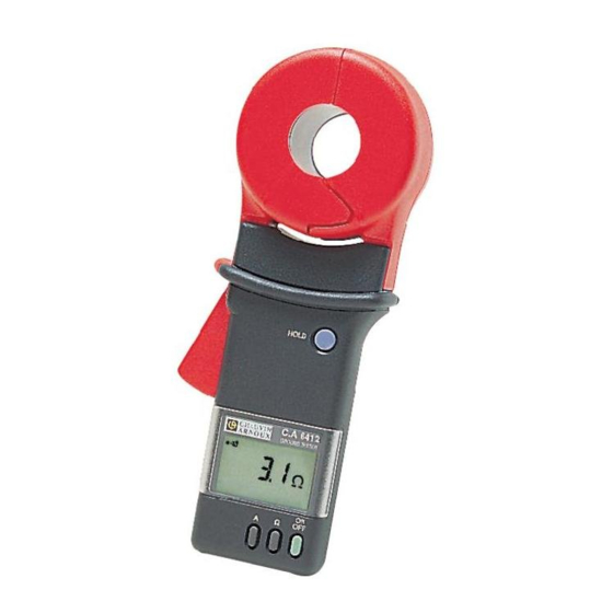
GROUND TESTER
I I I I I
ERDUNGSPRÜFZANGE
I I I I I
PINZA DI TERRA
I I I I I
PINZA DE TIERRA
F R A N C A I S
Notice de fonctionnement
E N G L I S H
User's Manual
D E U T S C H
Bedienungsanleitung
I T A L I A N O
Libretto d'Istruzioni
E S P A N O L
Manual de Instrucciones
C.A 6410
C.A 6412
C.A 6415
1
Advertisement
Table of Contents

Related Manuals for Chauvin Arnoux C.A 6410


Summary of Contents for Chauvin Arnoux C.A 6410
- Page 1 C.A 6410 I I I I I PINCE DE TERRE I I I I I C.A 6412 GROUND TESTER I I I I I ERDUNGSPRÜFZANGE C.A 6415 I I I I I PINZA DI TERRA I I I I I...
- Page 2 ENGLISH Meaning of the symbol Warning ! Please refer to the User’s Manual before using the instrument. In this User’s Manual, the instructions preceded by the above symbol, should they not be carried out as shown, can result in a physical accident or dammage the instrument and the installations.
-
Page 3: Table Of Contents
SUMMARY Page WARRANTY ....................28 TO ORDER ....................28 PRESENTATION ....................29 DESCRIPTION (diagrams at end of user’s manual) ......... 29 Instrument ....................29 Display ....................30 "How to use" labels ................. 31 PRINCIPLE OF MEASUREMENT ..............32 OPERATION ................................ON/OFF Function ................... -
Page 4: Warranty
Our guarantee is applicable for twelve months after the date on which the equipment is made available (extract from our General Conditions of Sale, available on request). TO ORDER Reference GROUND TESTER C.A 6410 P01.1220.11 ..................GROUND TESTER C.A 6412 P01.1220.12... -
Page 5: Presentation
PRESENTATION The Earth Tester is designed for testing the resistances of any system of conductors which is a conductive loop. In particular, it enables measurements of earth resistances if it is in series in a loop with its continuity conductor and different earths (extended earth produced for example by means of a guard wire linking electricity pylons together, for energy transportation or telecommunications;... -
Page 6: Display
Model C.A 6415 exclusively 6 : Ω Ω Ω Ω Ω pushbutton - On alarm reset mode, raises the alarm threshold.* - On read memory mode, displays the next recording.* 7 : A pushbutton - In combination with the ON button (secondary function), switches On or Off the measurement recording mode. -
Page 7: How To Use" Labels
Note: When switching on the clamp, if the ON button is held down for more than 1 second, a quick automatic test is carried out on the entire display. All the available segments are displayed for this short time. In your User's Manual, only the segments exclusive to your clamp are shown. -
Page 8: Principle Of Measurement
PRINCIPLE OF MEASUREMENT The diagram below of the principle of measurement illustrates the general case of measurement of a loop resistance consisting of: - the ground rod Rx - the Earth - n ground rods - a guard wire looping together all these earths - The generating winding of the clamp develops an AC voltage with a constant level E. -
Page 9: Operation
OPERATION ON/OFF OPERATION ON/OFF switches ON, OFF, and gives access to the secondary functions of the instrument. When switched ON, if the ON button is still pressed, the whole display is lit. After being pressed for 2 seconds, the remaining service life of the battery is displayed as a % (display of flashing symbol). -
Page 10: Alarms (C.a 6415 Only)
ALARMS ( C.A 6415 exclusively Operation of the alarm On resistance measurement, the alarm function is swiched ON with the AL button (the symbol and the value of the alarm threshold are displayed). A switch located inside the instrument allows the choice of the type of alarm used: - Low alarm: indicates measurements below the alarm threshold. -
Page 11: Memory (C.a 6415 Only)
According to the type of alarm selected, crossing of the alarm threshold will be indicated by the appearance of and a continuous beep at high or low fre- quency. Press the AL button again to exit the alarm function (the symbol disappears). -
Page 12: Reading Recorded Measurements
Press sequence ON + A to exit the instrument from memory mode (the MEM symbol disappears from the display). If the instrument is switched off without memory mode being exited, this configuration will be saved. The instrument will therefore automatically reset to memory mode when it is next switched on again. -
Page 13: Special Symbols
SPECIAL SYMBOLS In addition to the battery service life which is accessible when ON is pressed when switching on, the clamp can display the battery level at any time: For an alkaline battery if the service life is less than 25 %: the symbol flashes, indicating that around 50 resistance measurements can be made with guaranteed values. -
Page 14: Summary Of Functions
SUMMARY OF FUNCTIONS Function Pushbutton All models ON/OFF * ON/OFF HOLD display HOLD - Switch Auto Off ON/OFF ON + HOLD The instrument is automatically on Ω units each time it is switched on. Models C.A 6412 and C.A 6415 only Ω... -
Page 15: Examples Of Displays
EXAMPLES OF DISPLAYS - Buzzer ON - Measurement of a loop resistance of 28.1 Ω - 8 recorded values in the memory (C.A 6415 exclusively) - Battery o.k. - Clamp correctly closed - No interference current disturbing the measurement - Alarm off (C.A 6415 exclusively) - Buzzer ON - Display HOLD on the last measurement of 16.8 A (C.A 6412 and C.A 6415 only) -
Page 16: Examples Of Use
EXAMPLES OF USE TESTING A LOOP CONNECTED TO AN EXTENDED EARTH - In some countries (US, Northern Europe, ...) the electricity supply company brings the live, negative and earth conductors to the final user. In order to get a good quality for the earth present throughout the distribution network, an extended earth is constituted from all the local earths in parallel: earths of electricity pylons, earths for buildings, ... -
Page 17: Testing The Equipotential Of Grounding Systems
Analysis: The values read must never exceed a few ohms, or a few tens of ohms. Higher values indicate the presence of a fault in the earth loop tested. Comparison with nearby loop values will allow you to locate the common faulty link. This must be subjected to further investigation: measurement of the continuity of the cable connected to the earth, measurement of the resistance of local earths isolated from the rest of the network, ... -
Page 18: Specifications
SPECIFICATIONS GENERAL SPECIFICATIONS Conformity to the EN 6110-1 Ed 95 standard: Instrument completely protected by double insulation EN 61010-2-032 Ed 95, 150 V, category III and degree of pollution 2 (class 2). Leakage line and distance in the air: 3.3 mm minimum Emission: NF EN 61326-1, ed 98 Immunity: NF EN 61326-1, ed 98 Limiting overloads:... -
Page 19: Metrological Specifications
METROLOGICAL SPECIFICATIONS Reference conditions Distortion conditions Reference conditions Ambient temperature 23°C ± 3 K Relative humidity 50% RH ± 10% Battery voltage 8 V ± 0.2 V External magnetic field < 40 A/m External electric field < 1 V/m Operating position Clamp horizontal Position of conductor in the clamp centred... - Page 20 Ω Ω Ω Ω Ω function (resistance measurement) for reference conditions Measurement 50.0 ranges in Ω Ω Ω Ω Ω to 1.00 to 50.0 to 100.0 to 200 to 400 to 600 to 1200 0.01 Ω 0.1 Ω 0.5 Ω 1 Ω...
- Page 21 Variations in the nominal working range Influence Limit of Parameter Influence (1) parameter operating influenced range typical Max. Temperature - 10 °C to 0.5 P/10°C 1.5 P/10°C + R Ω (0.05 Ω + 0.5 P)/10°C (0.05 Ω +1.5 P)/10°C + R +55°C Relative humidity 10 % RH to...
-
Page 22: Maintenance
MAINTENANCE For maintenance, use only specified spare parts. The manufacturer will not be held responsible for any accident occuring following a repair done other than by its After Sales Service or approved repairers. CLEANING - The jaw faces must be cleaned with a soft cloth. - Use only a damp cloth to clean the case. -
Page 23: Calibration Check
We advise you to check this instrument at least once a year. For checking and calibration of your instrument, please contact our accredited laboratories (list on request) or the Chauvin Arnoux subsidiary or Agent in your country. REPAIR Repairs under or out of guarantee: please return the product to your distributor... -
Page 24: Appendix (Operation Of Buzzer)
APPENDIX Descriptive table for operation of buzzer Length and frequency of beep 65 ms 125 ms 250 ms Continuous 2.5 kHz 4 kHz 2.5 kHz 1 kHz 1 kHz 4 kHz Press button - Button prohibited - Recording not possible Noise Inter- mittent...
Need help?
Do you have a question about the C.A 6410 and is the answer not in the manual?
Questions and answers