Sign In
Upload
Download
Table of Contents
Contents
Add to my manuals
Delete from my manuals
Share
URL of this page:
HTML Link:
Bookmark this page
Add
Manual will be automatically added to "My Manuals"
Print this page
×
Bookmark added
×
Added to my manuals
Manuals
Brands
Chauvin Arnoux Manuals
Test Equipment
C.A 6550
User manual
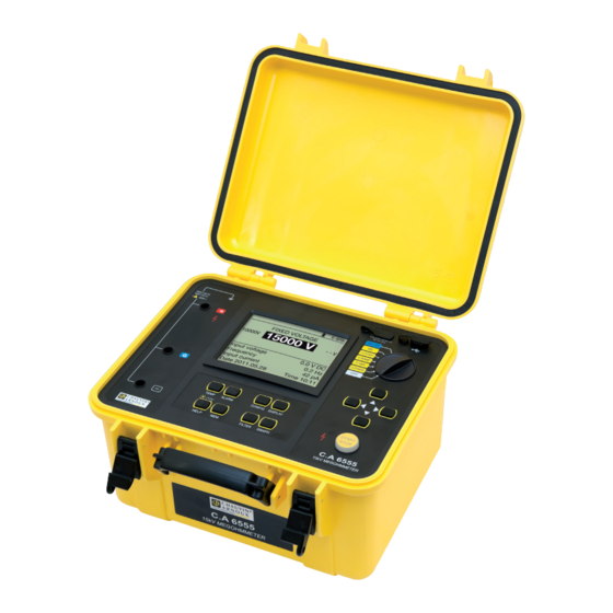
Chauvin Arnoux C.A 6550 User Manual
Megohmmeters 10 kv and 15kv
Hide thumbs
Also See for C.A 6550
:
User manual
(64 pages)
1
2
Table Of Contents
3
4
5
6
7
8
9
10
11
12
13
14
15
16
17
18
19
20
21
22
23
24
25
26
27
28
29
30
31
32
33
34
35
36
37
38
39
40
41
42
43
44
45
46
47
48
49
50
51
52
53
54
55
56
57
58
59
60
61
62
page
of
62
Go
/
62
Contents
Table of Contents
Bookmarks
Table of Contents
Table of Contents
1 First Use
Delivery Condition
Accessories
Replacement Parts
Specifications Label
Charging the Batteries
Adjusting the Brightness and Contrast
Display Contrast
Choice of Language
Choice of Measurement Cable Compensation
2 Description of the Instrument
Functions
Display
Keypad
PC Software
3 Procedure
Using the Leads
AC/DC Voltage Measurement
Insulation Measurement
Error Indications
DAR (Dielectric Absorption Ratio) and PI (Polarization Index)
DD (Dielectric Discharge Index)
Capacitance Measurement
Measurement of the Residual Current
4 Complementary Functions
TEMP Key
ALARM Key
CONFIG Key
DISPLAY Key
GRAPH Key
FILTER Key
HELP Key
5 Configuration (Set-Up)
Restoring the Initial Configuration
General Parameters
Measurement Parameters
Adjustment of the Test Voltages
Adjustment of the Alarm Thresholds
6 Memory Function
Recording of the Measurements
Reading Recorded Values
Erasing the Memory
List of Coded Errors
7 Data Transfer Software
8 Specifications
Reference Conditions
Characteristics Per Function
Power Supply
Environmental Conditions
Construction Specification
Compliance with International Standards
Variations in the Domain of Use
Intrinsic Uncertainty and Operating Uncertainty
9 Maintenance
Updating of the Internal Software
List of Parameters
10 Warranty
Advertisement
Quick Links
1
Insulation Measurement
2
List of Coded Errors
3
Data Transfer Software
4
Specifications
Download this manual
See also:
User Manual
GB - User's manual
Megohmmeters 10 kV and 15kV
C.A 6550
C.A 6555
Table of
Contents
Previous
Page
Next
Page
1
2
3
4
5
Advertisement
Table of Contents
Need help?
Do you have a question about the C.A 6550 and is the answer not in the manual?
Ask a question
Questions and answers
Related Manuals for Chauvin Arnoux C.A 6550
Multimeter Chauvin Arnoux C.A 6550 User Manual
Megohmmeters 10 kv and 15 kv (64 pages)
Test Equipment Chauvin Arnoux C.A 6549 User Manual
Megohmmeter (42 pages)
Test Equipment Chauvin Arnoux C.A 6555 User Manual
Megohmmeters 10 kv and 15kv (62 pages)
Test Equipment Chauvin Arnoux C.A 6423 User Manual
Earth tester (64 pages)
Test Equipment Chauvin Arnoux C.A 6030 User Manual
Residual current device tester (39 pages)
Test Equipment Chauvin Arnoux C.A 6116N User Manual
Installation tester (112 pages)
Test Equipment Chauvin Arnoux C.A 6416 User Manual
Ground tester (53 pages)
Test Equipment Chauvin Arnoux C.A 6417 User Manual
Ground tester (53 pages)
Test Equipment Chauvin Arnoux C.A 6609 User Manual
Motor and phase rotation indicator (13 pages)
Test Equipment Chauvin Arnoux C.A 6630 User Manual
Battery tester (92 pages)
Test Equipment Chauvin Arnoux C.A 6410 User Manual
(24 pages)
Test Equipment Chauvin Arnoux C.A 6470N TERCA 3 Manual
Earth and resistivity tester (12 pages)
Test Equipment Chauvin Arnoux TERCA 3 C.A 6470N User Manual
Earth and resistivity tester (48 pages)
Test Equipment Chauvin Arnoux C.A 6418 Manual
Oblong ground tester clamp (24 pages)
Test Equipment Chauvin Arnoux CA 6161 User Manual
Machine and panel tester (130 pages)
Test Equipment Chauvin Arnoux TERCA 3 User Manual
Earth and resistivity tester (48 pages)
This manual is also suitable for:
C.a 6555
Table of Contents
Print
Rename the bookmark
Delete bookmark?
Delete from my manuals?
Login
Sign In
OR
Sign in with Facebook
Sign in with Google
Upload manual
Upload from disk
Upload from URL


Need help?
Do you have a question about the C.A 6550 and is the answer not in the manual?
Questions and answers