Table of Contents
Advertisement
Advertisement
Table of Contents

Related Manuals for Chauvin Arnoux C.A 6116


Summary of Contents for Chauvin Arnoux C.A 6116
- Page 1 C.A 6116 InstAllAtIon tEstER User's manual E n G l I s H...
- Page 2 Thank you for purchasing a C.A 6116 installation tester. To obtain the best service from your unit: „ read these operating instructions carefully, „ comply with the precautions for use. WARNING, risk of DANGER! The operator must refer to these instructions whenever this danger symbol appears.
-
Page 3: Table Of Contents
ContEnts 1. fIRst stARt-UP ..................................4 1.1. Unpacking ..................................4 1.2. Charging the battery ............................... 5 1.3. Carrying the device ................................ 5 1.4. Contrast and brightness of the display .......................... 6 1.5. Choice of language ................................ 6 2. PREsEntAtIon of tHE DEvICE ............................8 2.1. -
Page 4: First Start-Up
1. fIRst stARt-UP 1.1. UnPACkInG FICHE DE SÉCURITÉ DU C.A 6116 (FR) Vous venez d’acquérir un contrôleur d’installation C.A 6116 et nous vous remercions de votre confiance. Pour obtenir le meilleur service de votre appareil : lisez attentivement cette notice de fonctionnement, ... -
Page 5: Charging The Battery
1.2. CHARGInG tHE bAttERy Before the first use, start by fully charging the battery. The charging must be done between 10 and 35°C. > 90 Vac < 264 Vac 50 / 60 Hz Battery loading... The indicator of the device lights. Battery charging connector of the device. -
Page 6: Contrast And Brightness Of The Display
To withdraw the strap, slide a flat screwdriver under the tab of the fastener to lift it, then slide the fastener down. 1.4. ContRAst AnD bRIGHtnEss of tHE DIsPlAy To adjust the contrast and the brightness of the display, press the key and one of the arrow keys simultaneously. - Page 7 Press the OK key to validate your choice. SET-UP Select your language, from among those proposed, using the keys and validate by pressing the OK key again. You can download other languages from our site’s support space (see §10.2).
-
Page 8: Presentation Of The Device
2. PREsEntAtIon of tHE DEvICE... -
Page 9: Functions Of The Device
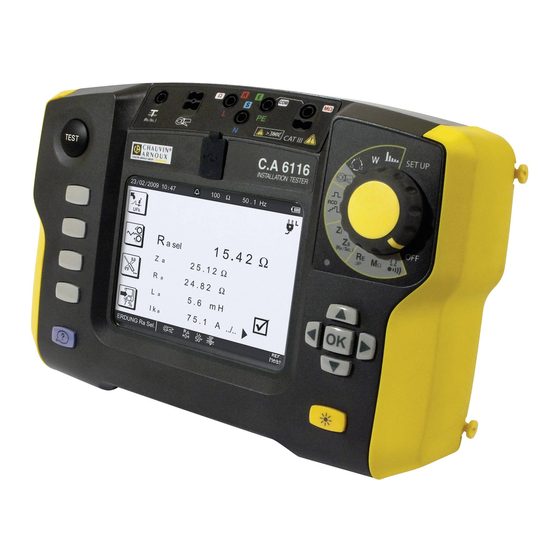
2.1. fUnCtIons of tHE DEvICE The C.A. 6116 installation tester is a portable measuring device with a monochrome graphic display. It is powered by a recharge- able battery with a built-in charger and external power supply unit. This device is intended to check the safety of electrical installations. It can be used to test a new installation before it is powered up, to check an existing installation, whether in operation or not, or to diagnose a malfunction in an installation. -
Page 10: Display Unit
2.3. DIsPlAy UnIt ➁ ➃ ➄ ➂ 50 . 0 Ω 50 . 1 Hz ➀ 02/09/2009 10:47 ➆ 6 mA 230.3 V L-PE 230.4 V ➅ ➇ 0.8 V N-PE ➈ LOOP Z ➉ Top strip Position of the phase on the socket outlet Date and time Display of measurement results Alarm threshold... -
Page 11: Procedure
3. PRoCEDURE When it leaves the plant, the device is configured so that it can be used without changing the parameters. For most measure- ments, simply select the measurement function by turning the switch and press the TEST key. However, you can also parameterize: „... -
Page 12: Resistance And Continuity Measurement
3.2. REsIstAnCE AnD ContInUIty MEAsUREMEnt 3.2.1. DEsCRIPtIon of tHE MEAsUREMEnt PRInCIPlE For continuity measurements, the device generates a DC current of 200 or 12 mA, at the user’s discretion, between the W and COM terminals. It then measures the voltage present between these two terminals and from it deduces the value of R = V/I. For resistance measurements (current chosen = kW), the device generates a DC voltage between the W and COM terminals. - Page 13 Automatic reversal of polarity for a measurement at 200 mA. Measurement at positive polarity only. Measurement at negative polarity only. To activate the alarm. To deactivate the alarm. Ω 002.00 To set the alarm threshold (see §3.15). The default threshold is 2W. k Ω...
- Page 14 To see the next display page. 2.00 Ω - - .- Hz 10/02/2009 10:47 0 . 0 V External voltage present on the Ω terminals just before the start of the measurement. Use the key to return to the previ- ../..
- Page 15 „ In the case of a resistance measurement (kW), there is no current reversal and no compensation for the measurement leads. 2.00 kΩ - - .- Hz 02/10/2009 10:47 Value of the alarm threshold. 1 . 5 8 k Ω Measurement result.
-
Page 16: Insulation Resistance Measurement
3.3. InsUlAtIon REsIstAnCE MEAsUREMEnt 3.3.1. DEsCRIPtIon of tHE MEAsUREMEnt PRInCIPlE The device generates a DC test voltage between the COM and MW terminals. The value of this voltage depends on the resistance to be measured: it is greater than or equal to U when R is greater than or equal to R /1 mA, and less otherwise. - Page 17 Once the parameters have been defined, you can start the measurement. keep the tEst button pressed until the measurement is stable. The measurement stops when the TEST button is released. TEST Before disconnecting the leads or starting another measurement, wait a few seconds for the device tested to be discharged (when the symbol disappears from the display unit).
- Page 18 To see the next display page. 500 kΩ - - .- Hz 02/11/2009 10:47 External voltage present on the 0 . 0 V M Ω terminals just before the start of the measurement. Press TEST until the measurement is stable Use the key to return to the previ- ../..
-
Page 19: Earth Resistance Measurement
3.4. 3P EARtH REsIstAnCE MEAsUREMEnt This function is the only one that can measure an earth resistance when the electrical installation to be tested is not live (new installation, for example). It uses two additional rods, with the third rod being constituted by the earth electrode to be tested (whence the name “3P”). - Page 20 Before the measurement: to display the measurements already recorded. During or after the measurement: to record it. The direction of the arrow indicates whether you can make a reading (arrow pointing out) or a recording (arrow pointing in). The percentage indicates the quantity of memory already used. If the measurement must be made in a damp environment, remember to change the value of maximum contact voltage U Setup (see §5) and set it to 25 V.
- Page 21 3.4.4. vAlIDAtIon of tHE MEAsUREMEnt To validate your measurement, move the S rod towards the H rod by 10% of d and make another measurement. Then move the S rod, again by 10% of d, but towards the earth electrode. 52% d 62% d 72% d...
- Page 22 3.4.6. ERRoR InDICAtIon The commonest errors in the case of an earth measurement are the presence of an interference voltage or rod resistances that are too high. If the device detects: „ a rod resistance greater than 15 kW, „ a voltage greater than 25 V on H or on S when the TEST button is pressed. In these two cases, the earth measurement is not enabled.
-
Page 23: Loop Impedance Measurement (Z )
3.5. looP IMPEDAnCE MEAsUREMEnt (Z In a TN or TT type installation, the loop impedance measurement is used to calculate the short-circuit current and to size the protections of the installation (fuses or RCDs), especially their breaking capacity. In a TT type installation, the loop impedance measurement makes it easy to determine the earth resistance without planting any rods and without cutting off power to the installation. - Page 24 For a more accurate measurement, you can choose a high current (TRIP mode), but the RCD that protects the installation may trip. The alarm, if activated, serves to inform the user, by an audible signal, that the measurement is above threshold, making it un- necessary to look at the display unit to check this point.
- Page 25 3.5.3. READInG of tHE REsUlt „ In the case of a non-tripping measurement, with smoothing: Value of the alarm threshold. 50 .0 Ω 50 . 1 Hz 02/16/2009 10:47 Value of the short-circuit current. 6 mA Value of the impedance. Value of the resistance.
-
Page 26: Measurement Of The Line Impedance (Z )
3.6. MEAsUREMEnt of tHE lInE IMPEDAnCE (Z The loop impedance measurement Zi (L-N, L1-L2, or L2-L3 or L1-L3) is used to calculate the short-circuit current and size the protec- tions of the installation (fuse or RCD), whatever type of neutral the installation uses. 3.6.1. - Page 27 Before starting the measurement, you can configure it by modifying the parameters displayed: To activate or deactivate the smoothing of the signal. To compensate for the resistance of the measurement leads, for measurements of low values (see §3.14). The device proposes choosing the voltage for the Ik calculation from among the following values: „...
- Page 28 3.6.3. 3.6.3. READInG of tHE REsUlt Value of the alarm threshold. 50 . 0 Ω 50 . 1 Hz 02/18/2009 10:47 Value of the short-circuit current. Value of the impedance. Value of the resistance. 1 3 1 6 A Value of the inductance. Case where the measurement is 0 .
- Page 29 3.7. EARtH MEAsUREMEnt on lIvE CIRCUIt (Z This function is used to make an earth resistance measurement in a place where it is impossible to make a 3P earth measurement or to disconnect the earth connection strap, often the case in an urban environment. This measurement is made without disconnecting the earth, with only one additional rod, saving time with respect to a conven- tional earth measurement with two auxiliary rods.
- Page 30 To make this measurement, you can choose: „ either a low current which avoids any untimely tripping out of the installation but gives only the earth resistance (RA). „ or a high current (TRIP mode), which yields a more accurate earth impedance (ZA) with good measurement stability. The alarm, if activated, serves to inform the user, by an audible signal, that the measurement is above threshold, making it un- necessary to look at the display unit to check this point.
- Page 31 3.7.3. READInG of tHE REsUlt „ In the case of a measurement with a high current (TRIP mode), without smoothing: Value of the alarm threshold. 50 . 0 Ω 50 . 1 Hz 02/20/2009 10:47 Value of the short-circuit current. Earth electrode fault voltage in the event of a short-circuit.
- Page 32 To see the next display page. 50 . 0 Ω 50 . 1 Hz 02/20/2009 10:47 2 5.1 0 Ω Value of the impedance. 2 4 . 8 Ω Value of the resistance. 5 . 6 Value of the inductance. Use the key to see the rest of the display of the measurement and the...
- Page 33 3.7.4. vAlIDAtIon of tHE MEAsUREMEnt Move the rod ± 10% of the distance from the earth electrode and make two more measurements. The 3 measurement results must be the same to within a few percent. In this case the measurement is valid. If this is not the case, this means that the rod is in the zone of influence of the earth electrode.
-
Page 34: Selective Earth Measurement On Live Circuit
3.8. sElECtIvE EARtH MEAsUREMEnt on lIvE CIRCUIt This function is used to make an earth measurement and to select one earth from among others, in parallel, and measure it. It requires the use of an optional current clamp. The C177 and MN77 clamps are better suited to these measurements because they are ten times as sensitive as the C177A clamp. - Page 35 Before starting the measurement, you can configure it by modifying the parameters displayed: The measurement current must be a high current (TRIP mode). To activate or deactivate the smoothing of the signal. To compensate for the resistance of the measurement leads (see §3.14). The selective earth meas- urement on live circuit is especially sensitive to any error in the compensation of the measurement leads.
- Page 36 3.8.3. READInG of tHE REsUlt Value of the alarm threshold. Ω 50 . 1 Hz 02/23/2009 10:47 Measurement result. Value of the current measured by the clamp. Value of the impedance. 3 8.4 2 Ω Asel Value of the resistance. Value of the inductance.
-
Page 37: Test Of Residual Current Device
3.9. tEst of REsIDUAl CURREnt DEvICE The device can be used to perform three types of test on RCDs: „ a tripping test in ramp mode, „ a tripping test in pulse mode, „ a non-tripping test. The test in ramp mode serves to determine the exact value of the tripping current of the RCD. The test in pulse mode serves to determine the tripping time of the RCD. - Page 38 If possible, first disconnect all loads from the network on which you test the RCD. This prevents interference with the test by any leakage currents due to these loads. If you have a current clamp, you can measure the leakage current (see §3.10) at the RCD and so make allowance for it during the test.
- Page 39 To restore the factory adjustment parameters: I = 30 mA, STD and types. To perform a prior check of voltage U , choose a test current: 0.2, 0.3, 0.4, or 0.5 I To make a faster measurement by eliminating the prior check of voltage U , choose: --x--.
- Page 40 3.9.4. MAkInG A tEst In PUlsE MoDE Connect the measuring cable to the device, then to a socket outlet included in the circuit protected by the circuit-breaker to be tested. Set the switch to RCD At the time of connection, the device detects the positions of the phase (L) and of neutral (N) with respect to the protective conductor (PE) and displays them.
- Page 41 „ Choice of type of residual current device: STD (standard), (the S type is tested with a current of 2 I default) „ Choice of pulse current: I x 1, I x 2, I x 5, 0,5 I /1s or 0.5 I /2s.
- Page 42 Press the TEST button to start the measurement. The measurement stops automatically. In the case of type S or G RCD, the device counts 30 seconds between the prior test of UF and the test of the RCD itself, in order to allow its demagnetization. This wait can be cut short by pressing the TEST key again. This symbol invites you to wait while the measurement is in progress.
- Page 43 „ In the case of a non-tripping test in pulse mode: 50 . 1 Hz 02/25/2009 10:47 30 mA or R 0.1 4 6 V The RCD did not trip out during the duration of application of the current of 0.5 I >...
-
Page 44: Current And Leakage Current Measurement
3.10. CURREnt AnD lEAkAGE CURREnt MEAsUREMEnt This measurement requires the use of a specific optional current clamp. It can measure very low currents (of the order of a few mA) like fault currents or leakage currents, and high currents (of the order of a few hundred Amperes). - Page 45 3.10.3. READInG of tHE REsUlt 010 . 0 A 50 . 1 Hz 02/26/2009 10:47 Value of the alarm threshold. 1 9 7.3 m A Measurement result. Case where the measurement is below the alarm threshold. CURRENT The clamp is connected. 3.10.4.
-
Page 46: Direction Of Phase Rotation
3.11. DIRECtIon of PHAsE RotAtIon This measurement is made on a three-phase network. It is used to check the phase order of the network. 3.11.1. DEsCRIPtIon of tHE MEAsUREMEnt PRInCIPlE The device checks that the three signals are at the same frequency, then compares the phases to determine their order (direct or reverse direction). - Page 47 Before the measurement: to display the measurements already recorded. After the measurement: to record it. The direction of the arrow indicates whether you can make a reading (arrow pointing out) or a recording (arrow pointing in). The percentage indicates the quantity of memory already used. 3.11.4.
-
Page 48: Power Measurement
3.12. PowER MEAsUREMEnt This measurement requires the use of the optional specific current clamp. It can be made on a single-phase network or on a three-phase network that is balanced in voltage and in current. 3.12.1. DEsCRIPtIon of tHE MEAsUREMEnt PRInCIPlE For a single-phase network, the device measures the voltage between the L and PE terminals, then multiplies it by the current measured by the clamp. - Page 49 3.12.3. READInG of tHE REsUlt 50 . 1 Hz 03/03/2009 10:47 Measurement result. The + sign indicates power con- sumed. The - sign indicates power returned. Voltage between the L and PE ter- 2 3 2 . 5 minals. 2 7 8 . 1 mA Current measured by the clamp.
- Page 50 However, on the C.A 6116, the sign of the PF is treated conventionally, meaning that it indicates only the phase advance or delay (inductive or capacitive load) and not whether a receiver or a generator is involved.
-
Page 51: Harmonics
3.13. HARMonICs This function is used to display the harmonic analysis of a voltage or current of which the signal is steady-state or quasi-steady- state. It is used to establish a first diagnostic of the harmonic pollution of an installation. The current analysis requires the use of the C177A current clamp (optional). - Page 52 3.13.3. READInG of tHE REsUlt 50 . 0 Hz 03/04/2009 10:47 THDF = 2,8 % Display of the THD-F and of the ULPE = 225,9 V RMS voltage. l o g Representation of the harmonics. 225,3 V Indication of the name of the se- 100,0 % lected spike and of its amplitude.
- Page 53 3.13.4. ERRoR InDICAtIon The commonest errors in the case of an analysis of a signal into harmonics are: „ The voltage is outside the measurement range. „ The frequency is outside the measurement range. „ The current is too low to be measured. „...
-
Page 54: Compensation For The Resistance Of The Measurement Leads
3.14. CoMPEnsAtIon foR tHE REsIstAnCE of tHE MEAsUREMEnt lEADs Compensation for the resistance of the measurement leads serves to neutralize their values and obtain a more accurate meas- urement when the resistance to be measured is low. The cords are already compensated in the plant, but if you use cords other than those provided, you can perform a new compensation. -
Page 55: Adjustment Of The Alarm Threshold
3.14.4. ElIMInAtInG tHE CoMPEnsAtIon Proceed as for compensation, but rather than short-circuiting the leads, leave them disconnected. Then press the TEST key. R∆ The device removes the compensation, then returns to voltage measurement. The symbol disappears from the display unit and the icon is crossed out. - Page 56 To validate the modified threshold, press the OK key. To abort without saving, press the key or turn the switch.
-
Page 57: Error Indication
4. ERRoR InDICAtIon Generally, errors are reported in clear language on screen. Example of error screen: Press the OK key to erase the message. Or press the help key for help in solving your problem. The following screen is then displayed. ... -
Page 58: No Connection
4.1. no ConnECtIon One or more terminals are not connected. 4.2. oUt of MEAsUREMEnt RAnGE > 4 0 . 0 W The value is outside the measurement range of the device. The minimum and maximum values depend on the function. <... -
Page 59: Check Of Internal Protection Devices
4.6. CHECk of IntERnAl PRotECtIon DEvICEs The device includes two internal protection devices that cannot be reset and that the user cannot replace. These devices act only under extreme conditions (e.g. a lightning strike). To check the condition of these protections: Disconnect the input terminals. -
Page 60: Set-Up
5. sEt-UP Use the directional keypad to select an icon, select Set the switch to SET-UP. a field, and modify it. SET UP Used to exit from the current screen. Used to display all parameters of the device: „ the software version (internal to the device), „... - Page 61 To return to the factory configuration (compensation for resistance of measurement leads and all adjustable parameters in the various measurements). The device requests confirmation before executing. The default configuration of the device is as follows: General configuration „ Audible signal: activated „...
- Page 62 Harmonics No default configuration. Each time the device is started up, the configuration is: „ Voltage harmonics. „ Display in bar-chart form with linear ordinates. „ Calculation of the total distortion referred to the fundamental (THD-F). To choose the language.
-
Page 63: Memory Function
6. MEMoRy fUnCtIon 6.1. oRGAnIZAtIon of tHE MEMoRy AnD nAvIGAtIon The device has 4000 memory locations to record measurements. They are organized in a tree on three levels, as follows: SITE 1 ROOM 1 OBJECT 1 OBJECT 2 ROOM 2 OBJECT 1 ... -
Page 64: Create A Tree
The following screen then appears: 500 kΩ - - .- Hz 03/05/2009 10:47 Site1 Position in the tree. To create a new SITE. To create a ROOM in a SITE or an OBJECT in a ROOM. To delete an element. To exit from the memory function. -
Page 65: Record The Measurement
To add a ROOM to a SITE, place the cursor on the chosen SITE and press the key. Give the ROOM a name and validate it. Then press the key again to create an OBJECT in the ROOM. This results in the following tree: 500 kΩ... -
Page 66: Read The Records
You can in this way make several insulation measurements on the electrical panel. And then move on to another type of measure- ment, still on the electrical panel, for example a loop impedance measurement. 50 . 1 Hz Ω 03/06/2009 10:47 LOOP LOOP L - PE As in the case of insulation, you can... - Page 67 Press the OK key to expand a TYPE OF TEST. 500 kΩ - - .- Hz 03/05/2009 10:47 House / Entry / Switchboard Path in the tree. INSULATION 1. - INSULAT. L1-PE 2. - INSULAT. L1-N List of tests performed in the Panel Zs (LOOP) OBJECT.
-
Page 68: Erasure
6.6. ERAsURE You can erase a SITE, a ROOM, an OBJECT or a record either when creating the tree or while reading in memory. Move the cursor onto the element to be erased using the keys of the directional keypad ( 500 kΩ... -
Page 69: Data Export Software
C.A. 6116 and removing the cover grams using the CD provided with the C.A. 6116. that protects the USB port of the device. C.A 6116 INSTALLATION TESTER Then, turn the device on by turning the switch to When the device is in communication with a PC, it any setting. -
Page 70: Technical Characteristics
8. tECHnICAl CHARACtERIstICs 8.1. GEnERAl REfEREnCE ConDItIons Quantity of influence Reference values Temperature 20 ± 3 °C Relative humidity 45 to 55 % HR Supply voltage 9.6 ± 0.2 V Frequency DC and 45 to 65 Hz Electric field < 1 V/m Magnetic field <... - Page 71 8.2.2. fREQUEnCy MEAsUREMEnts Particular reference conditions: Voltage ≥ 2 V ≥ 30 mA for the MN77 clamp, or current ≥ 10 mA for the C177 clamp, ≥ 50 mA for the C177A clamp. Beyond these values, the frequency is indeterminate (display of - - - - ). Measurement range 15.8 - 399.9 Hz 400.0 - 499.9 Hz...
- Page 72 8.2.5. InsUlAtIon REsIstAnCE MEAsUREMEnts Particular reference conditions: Capacitance in parallel: zero. Maximum acceptable external AC voltage during the measurement: zero. Frequency of external voltages: DC and 15.8 ... 65 Hz. The frequency is guaranteed only for a voltage ≥ 20 V . ≥...
- Page 73 8.2.6. 3P EARtH REsIstAnCE MEAsUREMEnts Particular reference conditions: Resistance of the E lead: zero or compensated. Interference voltages: zero. Inductance in series with the resistance: zero. ≤ 15,00 kW. ) / R < 300 and R < 100 x R with R and R up to 2.5 W.
- Page 74 Characteristics in non-tripping 3-wire mode: Measurement range 0.20 - 1.99 W 2.00 - 39.99 W 40.0 - 399.9 W 400 - 3999 W 0.01 W 0.1 W Resolution RMS measurement current choice of 6. 9. or 12 mA Intrinsic uncertainty on the im- ±...
- Page 75 Characteristics in 2-wire mode: Measurement range 0.080 - 0.500 W 0.510 - 3.999 W 4.00 - 19.99 W 20.0 - 39.99 W 40.0 - 399.9 W 400 - 3999 W Resolution 0.001 W 0.001 W 0.01 W 0.1 W Intrinsic uncertainty on the im- ±...
- Page 76 Calculation of the fault voltage if there is a short-circuit, U Measurement range 0.2 - 399.9 V 400 - 550 V Resolution 0.1 V = √ (Intrinsic uncertainty on the voltage measurement if U is used)² Intrinsic uncertainty MEAS + (Intrinsic uncertainty on the loop measurement)² Operating frequency 15.8 to 70 Hz Characteristics in non-tripping mode:...
- Page 77 8.2.10. tEst of REsIDUAl CURREnt DEvICE Particular reference conditions: Voltage of the installation: 90 to 500 V. Frequency of the installation: 15.8 to 17.5 Hz and 45 to 65 Hz. Contact voltage (potential of the protective conductor with respect to the local earth): <5 V. Resistance of the voltage probe (if used): <...
- Page 78 Domain of use of the ranges for a mains voltage between 280 and 500 v 10 mA 30 mA 100 mA 300 mA 500 mA 650 mA 1000 mA variable ≤ 500 mA Ramp or ...
- Page 79 Characteristics of the fault voltage calculation (U The device displays the value of the fault voltage for current I In the case of a loop measurement Z is calculated as follows: In the case of a loop measurement on a live circuit in tripping mode (TRIP), U is calculated as follows: In the case of a loop measurement on a live circuit in non-tripping mode, U is calculated as follows:...
- Page 80 8.2.11. CURREnt MEAsUREMEnt Particular reference conditions: Peak factor = 1,414 DC component< 0.1 %. Frequency: 15.8 450 Hz. For the measurement of I , the intrinsic uncertainty is increased by 5%. Characteristics with the Mn77 clamp: Transformation ratio: 1000 / 1 Measurement range 5.0 - 399.9 mA 0.400 - 3.999 A...
- Page 81 8.2.13. PowER MEAsUREMEnts Particular reference conditions: Sinusoidal voltage and current signals: cosj = 1. Voltage ≥ 10 V. Current ≥ 0.1 A (for the C177A clamp). Frequency: 15.8 to 65 Hz. No DC component. 40.0 - 110.0 kW Measurement range 5 - 3999 W 4.00 - 39.99 kW 40.0 - 330.0 kW...
-
Page 82: Variations In The Range Of Use
Method and definitions: Determination of harmonics: Cooley-Tukey FFT algorithm on 16 bits Sampling frequency: 256 times the frequency of the fundamental Filtering window: rectangular, 4 periods THD-F: Total distortion referred to the fundamental of the signal. n=50 √ Σ ² THD-F = THD-R: Total distortion referred to the RMS value of the signal (also called DF: distortion factor). - Page 83 8.3.3. REsIstAnCE AnD ContInUIty MEAsUREMEnt Variation of the measurement Quantities of influence Limits of the range of use Typical Maximum Temperature -10 … + 55 °C 1 %/10 °C ± 1 ct 2 %/10 °C + 2 ct Relative humidity 10 …...
- Page 84 8.3.6. EARtH MEAsUREMEnt on lIvE CIRCUIt, looP AnD sElECtIvE EARtH Variation of the measurement Quantities of influence Limits of the range of use Typical Maximum Temperature -10 … + 55 °C 1 %/10 °C ± 1 ct 2 %/10 °C + 2 ct Relative humidity 10 …...
-
Page 85: Intrinsic Uncertainty And Operating Uncertainty
8.4. IntRInsIC UnCERtAInty AnD oPERAtInG UnCERtAInty The C.A. 6116 installation tester complies with standard IEC-61557, which requires that the operating uncertainty, called B, be less than 30%. √ „ In insulation, B = ± ( |A| + 1,15 ² + E ²... - Page 86 If the device indicates that charging is over, it is perfectly acceptable to disconnect the charger for a few seconds, then reconnect it to top up the charge. Like any rechargeable battery, the one in your device is subject to significant spontaneous discharging, even when the device is off.
-
Page 87: Environmental Conditions
If charging proceeds normally, let the device perform a full charge. If, at the end of some time, the “defective battery” message appears once again, the battery must be replaced. 8.5.6. Enf of bAttERy lIfE The internal resistance of a battery at the end of its life is high. The result is an abnormally short charging time. After a full charge, the device indicates “charging over”, but as soon as the charger is disconnected, the display unit loses its contrast and goes off, meaning that the battery no longer holds a charge. -
Page 88: Definitions Of Symbols
9. DEfInItIons of syMbols Here is a list of the symbols used in this document and on the display unit of the device. 3-point earth resistance measurement with 2 auxiliary rods. AC (Alternating Current) signal. DC (Direct Current) signal. Distortion Factor = THD-R. E terminal (earth electrode, measurement current return terminal). - Page 89 tHD-R level of harmonic distortion referred to the RMS value of the signal. type of link to earth defined in standard IEC-60364-6. type of link to earth defined in standard IEC-60364-6. voltage between phases 1 and 2 of a three-phase network. voltage between phases 2 and 3 of a three-phase network.
-
Page 90: Maintenance
10. MAIntEnAnCE for maintenance, use only the spare parts specified. the manufacturer cannot be held liable for any accident that occurs following a repair not performed by its customer service department or by an approved repairer. 10.1. ClEAnInG Disconnect anything connected to the device and set the switch to OFF. Use a soft cloth, dampened with soapy water. -
Page 91: Resetting The Device
10.6. UPDAtInG of tHE IntERnAl softwARE With a view to providing, at all times, the best possible service in terms of performance and technical upgrades, Chauvin Arnoux invites you to update the embedded software of the device by downloading the new version, available free of charge on our web site. - Page 92 Connect the device to your PC using the USB cord provided. The update of the embedded software depends on its compatibility with the hardware version of the device. This version is, indicated in SET-UP (see § 5). warning: the update of the embedded software overwrites the whole configuration. As a precaution save the data to a PC before updating the embedded software.
-
Page 93: Warranty
11. wARRAnty Except as otherwise stated, our warranty is valid for twelve months starting from the date on which the equipment was sold. Extract from our General Conditions of Sale provided on request. The warranty does not apply in the following cases: „... -
Page 94: To Order
12. to oRDER C.A 6116 installation tester ............................P01145450 Delivered with: „ one carrying bag. „ one PA 30 W mains power unit, „ one hand strap, „ one 4-point hands-free strap, „ ICT data export software on CD-ROM, „ one 1.80m USB A/B cord with ferrite, „... - Page 96 Tel: +86 21 65 21 51 96 - Fax: +86 21 65 21 61 07 sCAnDInAvIA - CA Mätsystem Ab UsA - Chauvin Arnoux Inc - d.b.a AEMC Instruments Box 4501 - SE 18304 TÄBY 200 Foxborough Blvd. - Foxborough - MA 02035...
Need help?
Do you have a question about the C.A 6116 and is the answer not in the manual?
Questions and answers