Table of Contents
Advertisement
Advertisement
Table of Contents

Subscribe to Our Youtube Channel
Related Manuals for Chauvin Arnoux C.A 6116N


Summary of Contents for Chauvin Arnoux C.A 6116N
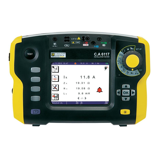
- Page 1 C.A 6116N InstAllAtIon tEstER C.A 6117 User's manual E n G l I s H...
- Page 2 Thank you for purchasing a C.A 6116N or C.A 6117 installation tester. To obtain the best service from your unit: „ read this user manual carefully, „ comply with the precautions for use. WARNING, risk of DANGER! The operator must refer to these instructions whenever this danger symbol appears.
-
Page 3: Table Of Contents
CONTENTS 1. FIRST START-UP ..................................4 1.1. Unpacking ..................................4 1.2. Charging the battery ..............................5 1.3. Carrying the device ..............................5 1.4. Use on a desktop .................................6 1.5. Brightness of the display .............................6 1.6. Choice of language ..............................7 2. PRESENTATION OF THE DEVICES .............................8 2.1. -
Page 4: First Start-Up
“ • One C.A 6116N or C.A 6117. One mains charger with cable for the battery. Data export software on CD-ROM and a USB A/B cord. One tripod cable with mains plug (adapted to the country of sale. -
Page 5: Charging The Battery
1.2. CHARGING THE BATTERY Before the first use, start by fully charging the battery. The charging must be done between 0 and 45°C. > 90 V < 264 V 50 / 60 Hz Battery loading... The indicator of the device lights. Remove the cover from the mains connector on the device. -
Page 6: Use On A Desktop
To withdraw the strap, slide a flat screwdriver under the tab of the fastener to lift it, then slide the fastener down. 1.4. USE ON A DESKTOP For use on a desktop, have the device rest on the fasteners of the hand strap and on the housing. This lets the display unit be read directly. -
Page 7: Choice Of Language
1.6. CHOICE OF LANGUAGE Before using the device, first choose the language in which you want the device to display messages. Set the switch to SET-UP. Use the directional keypad to select the languages icon: SET UP Press the OK key to validate your choice. -
Page 8: Presentation Of The Devices
2. PRESENTATION OF THE DEVICES TEST button to start Switch for selection the measurements. of the measurement function or SETUP. Connection terminals. TEST F o u r f u n c t i o n keys. SET UP Indicator light. Directional keypad: Stud for fixing on the four navigation keys... -
Page 9: Functions Of The Devices
2.1. FUNCTIONS OF THE DEVICES C.A 6116N and C.A 6117 installation testers are portable measuring devices with a colour graphic display. They are powered by a rechargeable battery with a built-in charger and external power supply unit. These instruments are intended to check the safety of electrical installations. It can be used to test a new installation before it is powered up, to check an existing installation, whether in operation or not, or to diagnose a malfunction in an installation. -
Page 10: Display Unit
2.3. DISPLAY UNIT ➁ ➃ ➄ ➂ 50 . 0 Ω 50 . 1 Hz ➀ 11-21-2013 10:47 ➆ 6 mA 230.3 V L-PE 230.4 V ➅ ➇ 0.8 V N-PE ➈ LOOP Z ➉ Top strip Position of the phase on the socket outlet Date and time Display of measurement results Alarm threshold... -
Page 11: Use
3. USE 3.1. GENERAL When it leaves the plant, the device is configured so that it can be used without changing the parameters. For most meas- urements, simply select the measurement function by turning the switch and press the TEST button. However, you can also parameterize: „... - Page 12 3.2.2. MAKING A MEASUREMENT Connect the lead to the device to be tested. As soon as the device is powered up, it measures the voltages present on its terminals and displays them, whatever the setting of the switch. In the Z ) and RCD, settings, the device also indicates the position of the phase on the display unit using the symbol.
-
Page 13: Resistance And Continuity Measurement
3.3. RESISTANCE AND CONTINUITY MEASUREMENT 3.3.1. DESCRIPTION OF THE MEASUREMENT PRINCIPLE For continuity measurements, the device generates a DC current of 200 or 12 mA, at the user’s discretion, between the W and COM terminals. It then measures the voltage present between these two terminals and from it deduces the value of R = V/I. For resistance measurements (current chosen = kW), the device generates a DC voltage between the W and COM terminals. - Page 14 Automatic reversal of polarity for a measurement at 200 mA. Measurement at positive polarity only. Measurement at negative polarity only. To activate the alarm. To deactivate the alarm. Ω 002.00 To set the alarm threshold (see §3.17). The default threshold is 2W. k Ω...
- Page 15 To see the next display page. 2.00 Ω - - .- Hz 22/07/2014 10:47 200 mA 0 . 0 V External voltage present on the Ω terminals just before the start of the measurement. L - PE 0 . 00 V L - N N - PE CIAGLOSC...
- Page 16 „ In the case of a resistance measurement (kW), there is no current reversal and no compensation for the measurement leads. - - .- Hz 11-22-2013 10:47 kΩ 1 . 5 8 k Ω Measurement result. Case where the measurement is below the alarm threshold.
-
Page 17: Insulation Resistance Measurement
3.4. INSULATION RESISTANCE MEASUREMENT 3.4.1. DESCRIPTION OF THE MEASUREMENT PRINCIPLE The device generates a DC test voltage between the COM and MW terminals. The value of this voltage depends on the resistance when R ≥ R to be measured: it is greater than or equal to U /1 mA, and less otherwise. - Page 18 3.4.3. CONFIGURING THE MEASUREMENT Before starting the measurement, you can configure it by modifying the parameters displayed: To choose the nominal test voltage UN: 50, 100, 250, 500 or 1000 V. To activate the alarm. To deactivate the alarm. k Ω 0500.0 To set the alarm threshold (see §3.17).
- Page 19 To see the next display page. 500 kΩ - - .- Hz 11-22-2013 10:47 0 . 3 V M Ω External voltage present on the L - PE terminals just before the start of the measurement. L - N N - PE Press TEST until the measurement is stable...
-
Page 20: Earth Resistance Measurement
3.5. 3P EARTH RESISTANCE MEASUREMENT This function is the only one that can measure an earth resistance when the electrical installation to be tested is not live (new in- stallation, for example). It uses two auxiliary rods, with the third rod being constituted by the earth electrode to be tested (whence the name “3P”). - Page 21 To activate the alarm. To deactivate the alarm. Ω 050.00 To set the alarm threshold (see §3.17). As default, the threshold is set to 50W. k Ω Before the measurement: to display the measurements already recorded. During or after the measurement: to record it. The direction of the arrow indicates whether you can make a reading (arrow pointing out) or a recording (arrow pointing in).
- Page 22 3.5.5. VALIDATION OF THE MEASUREMENT To validate your measurement, move the S rod towards the H rod by 10% of d and make another measurement. Then move the S rod, again by 10% of d, but towards the earth electrode. 52% d 62% d 72% d...
- Page 23 3.5.7. ERROR INDICATION The commonest errors in the case of an earth measurement are the presence of an interference voltage or rod resistances that are too high. If the device detects: „ a rod resistance greater than 15 kW, „ a voltage greater than 25 V on H or on S when the TEST button is pressed. In these two cases, the earth measurement is not enabled.
-
Page 24: Loop Impedance Measurement (Z )
3.6. LOOP IMPEDANCE MEASUREMENT (Z In a TN or TT type installation, the loop impedance measurement is used to calculate the short-circuit current and to size the pro- tections of the installation (fuses or RCDs), especially their breaking capacity. In a TT type installation, the loop impedance measurement makes it easy to determine the earth resistance without planting any rods and without cutting off power to the installation. - Page 25 For a more accurate measurement, you can choose a high current (TRIP mode), but the RCD that protects the installation may trip. The alarm, if activated, serves to inform the user, by an audible signal, that the measurement is above threshold, making it un- necessary to look at the display unit to check this point.
- Page 26 You can then choose: „ The delay (the duration of application of I before the fuse blows): 0.1s, 0.2s, 0.4s, 5s, or 35ms. „ The type of fuse: gG, LSB, LSC or LSD. „ The rated current I : any standardized value between 2 and 1000A. The choices available depend on the choices already made.
- Page 27 3.6.4. READING OF THE RESULT „ In the case of a non-tripping measurement, with smoothing: Value of the alarm threshold. 50 .0 Ω 50 . 1 Hz 11-22-2013 10:47 Value of the short-circuit current. 6 mA Value of the impedance. Value of the resistance.
-
Page 28: Earth Measurement On Live Circuit (Z )
3.7. EARTH MEASUREMENT ON LIVE CIRCUIT (Z This function is used to make an earth resistance measurement in a place where it is impossible to make a 3P earth measurement or to disconnect the earth connection strap, often the case in an urban environment. This measurement is made without disconnecting the earth, with only one additional rod, saving time with respect to a conventional earth measurement with two auxiliary rods. - Page 29 To make this measurement, you can choose: „ either a low current which avoids any untimely tripping out of the installation but gives only the earth resistance (R „ or a high current (TRIP mode), which yields a more accurate earth impedance (Z ) with good measurement stability and can also be used to calculate the short-circuit fault voltage, U in accordance with standard SEV 3569.
- Page 30 Press the TEST button to start the measurement. The measurement stops automatically. This symbol invites you to wait while the measurement is in progress. TEST 3.7.4. READING OF THE RESULT „ In the case of a measurement with a high current (TRIP mode), without smoothing: Value of the alarm threshold.
- Page 31 To see the next display page. 50 . 0 Ω 50 . 1 Hz 11-25-2013 10:47 2 5.1 0 Ω Value of the impedance. 2 4 . 8 Ω Value of the resistance. 5 . 6 Value of the inductance. To change display pages.
- Page 32 3.7.5. VALIDATION OF THE MEASUREMENT Move the rod ± 10% of the distance from the earth electrode and make two more measurements. The 3 measurement results must be the same to within a few percent. In this case the measurement is valid. If this is not the case, this means that the rod is in the zone of influence of the earth electrode.
-
Page 33: Selective Earth Measurement On Live Circuit
3.8. SELECTIVE EARTH MEASUREMENT ON LIVE CIRCUIT This function is used to make an earth measurement and to select one earth from among others, in parallel, and measure it. It requires the use of an optional current clamp. 3.8.1. DESCRIPTION OF THE MEASUREMENT PRINCIPLE The device starts by making a loop measurement Z between L and PE (see §3.6) with a high current, and therefore with a risk of tripping out the installation. - Page 34 In the selective earth measurement on live circuit, it is essential to do a compensation of the measurement leads and to redo it if it has not been done recently or if you have changed leads. 3.8.3. CONFIGURING THE MEASUREMENT Before starting the measurement, you can configure it by modifying the parameters displayed: The measurement current must be a high current (TRIP mode).
- Page 35 3.8.4. READING OF THE RESULT Value of the alarm threshold. 50 . 0 Ω 50 . 1 Hz 11-25-2013 10:47 Measurement result. Value of the current measured by the clamp. Value of the impedance. 3 8.4 2 Ω Asel Value of the resistance. Value of the inductance.
-
Page 36: Measurement Of The Line Impedance (Z )
3.9. MEASUREMENT OF THE LINE IMPEDANCE (Z The loop impedance measurement Zi (L-N, L1-L2, or L2-L3 or L1-L3) is used to calculate the short-circuit current and size the protec- tions of the installation (fuse or RCD), whatever type of neutral the installation uses. 3.9.1. - Page 37 3.9.3. CONFIGURING THE MEASUREMENT Before starting the measurement, you can configure it by modifying the parameters displayed: To select measurement of Zi (line impedance measurement) or of DV (measurement of the voltage drop in the cables, for the C.A. 6117 only). Here, you must select Z To compensate for the resistance of the measurement leads, for measurements of low values (see §3.16).
- Page 38 You can then choose: „ The delay (the duration of application of I before the fuse blows): 0.1s, 0.2s, 0.4s, 5s, or 35ms. „ The type of fuse: gG, LSB, LSC or LSD. „ The rated current I : any standardized value between 2 and 1000A. The choices available depend on the choices already made.
- Page 39 3.9.4. READING OF THE RESULT Value of the alarm threshold. 50 . 0 Ω 50 . 1 Hz 11-25-2013 10:47 Value of the short-circuit current. Value of the impedance. Value of the resistance. 1 3 1 6 A Value of the inductance. Case where the measurement is 0 .
-
Page 40: Measurement Of The Voltage Drop In The Cables (Dv)
3.10. MEASUREMENT OF THE VOLTAGE DROP IN THE CABLES (DV) For the C.A. 6117 only. The voltage drop in the cables is measured to check that the cross section of the cables is sufficient for the installation. A voltage drop that is too large (> 5%) means that the cross section of the cables is too small. This measurement can be made whatever the type of neutral used in the installation. - Page 41 The alarm, if activated, serves to inform the user, by an audible signal, that the measurement is above threshold, making it un- necessary to look at the display unit to check this point. The signal can be smoothed to produce a mean of values. But the measurement then takes longer. For this measurement, it is not necessary to connect the PE terminal.
- Page 42 3.10.4. READING OF THE RESULT After the first measurement: 50 . 1 Hz 01/17/2017 10:47 Value of the short-circuit current. Value of the reference impedance. Value of the resistance. 1 3 1 6 A Value of the inductance. 0 . 8 3 6 Ω r e f Press the key to enter the meas-...
-
Page 43: Test Of Residual Current Device
3.11. TEST OF RESIDUAL CURRENT DEVICE The device can be used to perform three types of test on RCDs: „ a tripping test in ramp mode, „ a tripping test in pulse mode, „ a non-tripping test. The test in ramp mode serves to determine the exact value of the tripping current of the RCD. The test in pulse mode serves to determine the tripping time of the RCD. - Page 44 If possible, first disconnect all loads from the network on which you test the RCD. This prevents interference with the test by any leakage currents due to these loads. If you have a current clamp, you can measure the leakage current (see §3.12) at the RCD and so make allowance for it during the test. To make a more accurate measurement of the fault voltage, plant the auxiliary rod at a distance of more than 25 metres from the earth electrode and connect it to the ) terminal of the device.
- Page 45 3.11.3. CONFIGURING THE MEASUREMENT Before starting the measurement, you can configure it by modifying the parameters displayed: „ Choice of the nominal current of the residual current device I : VAR. (variable: the user programs a value be- tween 6 and 999mA for types AC, A, and F, or a value between 6 and 499 mA for types B, B+, and EV), 6 mA, 30 mA 10 mA, 30 mA, 100 mA, 300 mA, 500 mA, 650 mA or 1000 mA (except 1000 A for types B, B+, and EV residual current devices).
- Page 46 3.11.4. READING OF THE RESULT 50 . 1 Hz 11-25-2013 10:47 30 mA or R 1.0 7 3 V Tripping current. 2 2.3 m A Tripping time. 1 3.8 m s The measurement results are correct. To change display pages. RCD : Ia Type of signal.
- Page 47 3.11.5. MAKING A TEST IN PULSE MODE Connect the measuring cable to the device, then to a socket outlet included in the circuit protected by the circuit-breaker to be tested. Set the switch to RCD At the time of connection, the device detects the positions of the phase (L) and of neutral (N) with respect to the protective conductor (PE) and displays them.
- Page 48 3.11.6. CONFIGURING THE MEASUREMENT Before starting the measurement, you can configure it by modifying the parameters displayed: „ Choice of the nominal current of the residual current device I : VAR. (variable: the user programs a value be- tween 6 and 999 mA for types AC, A, and F, or a value between 6 and 499 mA for types B, B+, and EV), 6 mA, 30 mA 10 mA, 30 mA, 100 mA, 300 mA, 500 mA, 650 mA or 1000 mA (except 1000 A for types B, B+, and EV residual current devices).
- Page 49 Before the measurement: to display the measurements already recorded. During or after the measurement: to record it. The direction of the arrow indicates whether you can make a reading (arrow pointing out) or a recording (arrow pointing in). The percentage indicates the quantity of memory already used. ...
- Page 50 „ In the case of a non-tripping test in pulse mode: 50 . 1 Hz 11-25-2013 10:47 30 mA or R 0.1 4 6 V The RCD did not trip out during the duration of application of the current of 0.5 I >...
-
Page 51: Current And Leakage Current Measurement
3.12. CURRENT AND LEAKAGE CURRENT MEASUREMENT This measurement requires the use of a specific optional current clamp. It can measure very low currents (of the order of a few mA) like fault currents or leakage currents, and high currents (of the order of a few hundred Amperes). - Page 52 3.12.4. READING OF THE RESULT 010 . 0 A 50 . 1 Hz 11-25-2013 10:47 Value of the alarm threshold. 1 9 7.3 m A Measurement result. Case where the measurement is below the alarm threshold. CURRENT The clamp is connected. 3.12.5.
-
Page 53: Direction Of Phase Rotation
3.13. DIRECTION OF PHASE ROTATION This measurement is made on a three-phase network. It is used to check the phase order of the network. 3.13.1. DESCRIPTION OF THE MEASUREMENT PRINCIPLE The device checks that the three signals are at the same frequency, then compares the phases to determine their order (direct or reverse direction). - Page 54 Before the measurement: to display the measurements already recorded. During or after the measurement: to record it. The direction of the arrow indicates whether you can make a reading (arrow pointing out) or a recording (arrow pointing in). The percentage indicates the quantity of memory already used. 3.13.4.
-
Page 55: Power Measurement
3.14. POWER MEASUREMENT This measurement requires the use of the optional specific C177A current clamp. It can be made on a single-phase network or on a three-phase network that is balanced in voltage and in current. 3.14.1. DESCRIPTION OF THE MEASUREMENT PRINCIPLE For a single-phase network, the device measures the voltage between the L and PE terminals, then multiplies it by the current meas- ured by the clamp. - Page 56 3.14.4. READING OF THE RESULT 50 . 1 Hz 11-25-2013 10:47 Measurement result. The + sign indicates power con- sumed. The - sign indicates power returned. Voltage between the L and PE ter- 2 3 2 . 5 minals. 2 7 8 . 1 mA Current measured by the clamp.
- Page 57 3.14.5. POWER FACTOR In the case of sinusoidal signals, the sign of cos j indicates whether the measurement is being made on a generator (cos j < 0) or on a receiver (cos j > 0). The power factor, PF, can be regarded as equivalent to cos j but generalized to non-sinusoidal signals, which is often the case with currents.
-
Page 58: Harmonics
3.15. HARMONICS This function is used to display the harmonic analysis of a voltage or current of which the signal is steady-state or quasi-steady- state. It is used to establish a first diagnostic of the harmonic pollution of an installation. The current analysis requires the use of the C177A current clamp (optional). - Page 59 3.15.4. READING OF THE RESULT 50 . 0 Hz 01-23-2013 10:47 THDF = 2.8 % Display of the THD-F and of the RMS ULPE = 225.9 V voltage. l o g Representation of the harmonics. 225.3 V Indication of the name of the selected 100.0 % spike and of its amplitude.
- Page 60 3.15.5. ERROR INDICATION The commonest errors in the case of an analysis of a signal into harmonics are: „ The voltage is outside the measurement range. „ The frequency is outside the measurement range. „ The current is too low to be measured. „...
-
Page 61: Compensation For The Resistance Of The Measurement Leads
3.16. COMPENSATION FOR THE RESISTANCE OF THE MEASUREMENT LEADS Compensation for the resistance of the measurement leads serves to neutralize their values and obtain a more accurate meas- urement when the resistance to be measured is low. The cords are already compensated in the plant; you must perform a new compensation if you use cords other than those provided. - Page 62 3.16.4. ELIMINATING THE COMPENSATION Proceed as for compensation, but rather than short-circuiting the leads, leave them disconnected. Then press the TEST button. R∆ The device removes the compensation, then returns to voltage measurement. The symbol disappears from the display unit and the icon is crossed out.
-
Page 63: Adjustment Of The Alarm Threshold
3.17. ADJUSTMENT OF THE ALARM THRESHOLD The device makes an audible signal and the indicator flashes: „ in continuity, resistance and insulation measurement, if the measurement is below threshold; „ for earth and loop measurements and measurements of the voltage drop in the cables, if the measurement is above threshold; „... -
Page 64: Error Indication
4. ERROR INDICATION Generally, errors are reported in clear language on screen. Example of error screen: Press the OK key to erase the message. Or press the help key for help in solving your problem. The following screen is then displayed. Press the OK key or the key to exit from the help function. -
Page 65: No Connection
4.1. NO CONNECTION One or more terminals are not connected. 4.2. OUT OF MEASUREMENT RANGE > 4 0 . 0 W The value is outside the measurement range of the device. The minimum and maximum values depend on the function. <... -
Page 66: Check Of Internal Protection Devices
4.6. CHECK OF INTERNAL PROTECTION DEVICES The device includes two internal protection devices that cannot be reset and that the user cannot replace. These devices act only under extreme conditions (e.g. a lightning strike). To check the condition of these protections: Disconnect the input terminals. -
Page 67: Set-Up
5. SET-UP Set the switch to SET-UP. SET UP Use the directional keypad to select an icon, select a field, and modify it. This key is used to exit from the current screen without saving. Used to display all parameters of the device: „... - Page 68 ∞ Adjustment of the time to automatic switching off of the device: 5 min (default), 10 min, 30 min, or (per- manent operation). Used to access the memory to: „ read the measurements already made, „ or prepare a tree before a measurement campaign. See storage in §6.
- Page 69 Measurement of the voltage drop in the cables (DV) „ Alarm activated. „ Alarm threshold: 5%. Test of RCD „ Nominal range I = 30 mA. „ Type of circuit-breaker: Standard (STD). „ Test waveform: sinusoidal signal that begins with a positive half-wave. „...
-
Page 70: Memory Function
6. MEMORY FUNCTION 6.1. CHOICE OF MODE The memory can be used in 2 different modes: „ Tree mode „ Table mode 6.1.1. TREE MODE In tree mode, the measurements are organized as follows: SITE 1 ROOM 1 OBJECT 1 OBJECT 2 ROOM 2 OBJECT 1... -
Page 71: Tree Mode
6.2. TREE MODE 6.2.1. ORGANIZATION OF THE MEMORY AND NAVIGATION The device has 1000 memory locations to record measurements. They are organized in a tree on three levels, as follows: SITE 1 ROOM 1 OBJECT 1 OBJECT 2 ROOM 2 ... - Page 72 The following screen then appears: 500 kΩ - - .- Hz 11-25-2013 10:47 Site1 Position in the tree. To create a new SITE. To create a ROOM in a SITE or an OBJECT in a ROOM. To delete an element. To exit from the memory function.
- Page 73 To add a ROOM to a SITE, place the cursor on the chosen SITE and press the key. Give the ROOM a name and validate it. Then press the key again to create an OBJECT in the ROOM. This results in the following tree: 500 kΩ...
- Page 74 You can in this way make several insulation measurements on the electrical panel. And then move on to another type of measure- ment, still on the electrical panel, for example a loop impedance measurement. 50 . 1 Hz Ω 11/24/2017 10:47 LOOP LOOP L - PE...
- Page 75 Press the OK key to expand a TYPE OF TEST. 500 kΩ - - .- Hz 11-25-2013 10:47 House / Entry / Switchboard Path in the tree. INSULATION 1. - INSULAT. L1-PE 2. - INSULAT. L1-N List of tests performed in the Panel Zs (LOOP) OBJECT.
-
Page 76: Table Mode
6.2.6. ERASURE You can erase a SITE, a ROOM, an OBJECT or a record either when creating the tree or while reading in memory. Move the cursor onto the element to be erased using the keys of the directional keypad ( ). 500 kΩ... - Page 77 The following screen then appears: 500 kΩ - - .- Hz 01/17/2017 10:47 To move up 100 objects. To move down 100 objects. To delete a recording. To exit from the memory function. INSULATION Use the arrows to select the object in which you want to record your measurement and validate by pressing the OK key. For insulation, loop impedance, line impedance, current, and power measurements and the harmonic analysis, the device proposes indexing your measurement, because several measurements are possible.
- Page 78 6.3.2. READ THE RECORDS You can read the measurement made by pressing the key (arrow pointing out). The device then displays the list of objects, going to the last object in which a measurement was recorded. 500 kΩ - - .- Hz 01/17/2017 10:47 INSULATION A status symbol displayed to the right of an object indicates:...
- Page 79 Press the OK key to expand one type of test. 500 kΩ - - .- Hz 01/17/2017 10:47 ===> 001 Object number. INSULATION INSULAT. L1-PE INSULAT. L1-N List of tests performed in the object. Zs (LOOP) LOOP L1-PE LOOP L2-PE INSULATION Use the ( ...
- Page 80 6.3.4. ERRORS When the memory is full, you can no longer record measurements. You must then delete at least one object to be able to record your new measurement.
-
Page 81: Data Export Software
7. DATA EXPORT SOFTWARE The data export software is in two parts: „ ICT (Installation Controller Transfer), used to configure the parameters of the measurements, prepare the tree in memory, and export the recorded measurements in an Excel file. „ Dataview, used to recover the measurements from the Excel file and present them in the form of a report conforming to the standard in your country. -
Page 82: Technical Characteristics
8. TECHNICAL CHARACTERISTICS 8.1. GENERAL REFERENCE CONDITIONS Quantity of influence Reference values 20 ± 3 °C Temperature Relative humidity 45 to 55 % HR Supply voltage 10.6 ± 0.2 V Frequency DC and 45 to 65 Hz Electric field < 1 V/m Magnetic field <... - Page 83 Measurements of potential of the voltage probe The characteristics are the same as in the voltage measurements except that the input impedance is 200 kW. This voltage must normally be between 0 and U 8.2.2. FREQUENCY MEASUREMENTS Particular reference conditions: ≥...
- Page 84 8.2.4. RESISTANCE MEASUREMENTS Particular reference conditions: External voltage on the terminals: zero. Inductance in series with the resistance: zero. Measurement range 0.001 - 3.999 kW 4.00 - 39.99 kW 40.0 - 399.9 kW 10 W 100 W Resolution ≤ 22 µA ≤...
- Page 85 Typical measurement settling time as a function of the elements tested These values include influences due to the capacitive component of the load, to the automatic range system, and to the regulation of the test voltage. Test voltage Load Non-capacitive With 100 nF With 1 µF 10 MW...
- Page 86 Characteristics in trip mode: 0.100 - 0.500 W 0.510 - 3.999 W 4.00 - 39.99 W 40.0 - 399.9 W Measurement range 0.001 W 0.01 W 0.1 W Resolution Intrinsic uncertainty on the impedance measurement ± (10% + 20 ct) ±...
- Page 87 Characteristics in selective mode: 0.50 - 39.99 W 40.0 - 399.9 W Measurement range 0.01 W 0.1 W Resolution Intrinsic uncertainty on the resist- ± (10% + 10 ct) ance measurement 5: there is no measurement of the inductive part in selective mode. The duration of the measurement depends on the voltage of the installation, on the measured impedance value, and on the activa- tion of the smoothing filter (SMOOTH).
- Page 88 8.2.10. VOLTAGE DROP IN THE CABLES Particular reference conditions: Voltage of the installation: 90 to 500 V. Stability of the voltage source: <0.05%. Frequency of the installation: 15.8 to 17.5 Hz and 45 to 65 Hz. Resistance of the leads: zero or compensated. Impedance of the inductive part: <...
- Page 89 Characteristics in pulse mode for type AC, A and F RCDs: 6 mA - 10 mA - 30 mA - 100 mA - 300 mA - 500 mA - 650 mA - 1000 mA Range I Variable (6 to 999 mA) Tripping test (se- Nature of the test Determination of U...
- Page 90 Limitation of the ranges available as a function of the voltage for type B, B+ and EV RCDs Variable 6 mA 10 mA 30 mA 100 mA 300 mA 500 mA 6 - 499 mA ...
- Page 91 8.2.12. CURRENT MEASUREMENT Particular reference conditions: Peak factor = 1,414 DC component< 0.1 %. Frequency: 15.8 450 Hz. For the measurement of I , the intrinsic uncertainty is increased by 5%. Characteristics with the MN77 clamp: Transformation ratio: 1000 / 1 Measurement range 5.0 - 399.9 mA 0.400 - 3.999 A...
- Page 92 8.2.14. POWER MEASUREMENTS Particular reference conditions: Sinusoidal voltage and current signals: cosj = 1. Voltage ≥ 10 V. Current ≥ 0.1 A (for the C177A clamp). Frequency: 15.8 to 17.5 Hz and 45 to 65 Hz. No DC component. 40.0 - 110.0 kW Measurement range 5 - 3999 W 4.00 - 39.99 kW...
-
Page 93: Variations In The Range Of Use
Method and definitions: Determination of harmonics: Cooley-Tukey FFT algorithm on 16 bits Sampling frequency: 256 times the frequency of the fundamental Filtering window: rectangular, 4 periods THD-F: Total distortion referred to the fundamental of the signal. n=50 √ Σ ² THD-F = THD-R: Total distortion referred to the RMS value of the signal (also called DF: distortion factor). - Page 94 8.3.3. RESISTANCE AND CONTINUITY MEASUREMENT Variation of the measurement Quantities of influence Limits of the range of use Typical Maximum -10 … + 55 °C 1 %/10 °C ± 1 ct 2 %/10 °C + 2 ct Temperature 10 … 85 % RH at 45°C Relative humidity 3 % + 2 ct Supply voltage...
- Page 95 8.3.6. EARTH MEASUREMENT ON LIVE CIRCUIT, LOOP AND SELECTIVE EARTH Variation of the measurement Quantities of influence Limits of the range of use Typical Maximum -10 … + 55 °C 1 %/10 °C ± 1 ct 2 %/10 °C + 2 ct Temperature 10 …...
-
Page 96: Intrinsic Uncertainty And Operating Uncertainty
8.4. INTRINSIC UNCERTAINTY AND OPERATING UNCERTAINTY The installation testers comply with standard IEC-61557, which requires that the operating uncertainty, called B, be less than 30%. √ „ In insulation, B = ± ( |A| + 1,15 ² + E ² + E ²... - Page 97 Set the switch to OFF; charging is possible when the device is not off, but will take longer. 8.5.3. OPTIMIZE BATTERY CHARGING During charging, the temperature of the battery rises, especially towards the end. A safety device, built into the battery, checks con- stantly that the battery temperature does not exceed an acceptable maximum.
-
Page 98: Environmental Conditions
8.5.5. END OF BATTERY LIFE The internal resistance of a battery at the end of its life is high. The result is an abnormally short charging time. After a full charge, the device indicates “charging over”, but as soon as the charger is disconnected, the display unit loses its contrast and goes off, meaning that the battery no longer holds a charge. -
Page 99: Definitions Of Symbols
9. DEFINITIONS OF SYMBOLS Here is a list of the symbols used in this document and on the display unit of the device. 3-point earth resistance measurement with 2 auxiliary rods. AC (Alternating Current) signal. DC (Direct Current) signal. Distortion Factor = THD-R. E terminal (earth electrode, measurement current return terminal). - Page 100 effective trip time of the residual current device. THD-F level of harmonic distortion referred to the fundamental. THD-R level of harmonic distortion referred to the RMS value of the signal. type of link to earth defined in standard IEC-60364-6. type of link to earth defined in standard IEC-60364-6. voltage between phases 1 and 2 of a three-phase network.
-
Page 101: Maintenance
10. MAINTENANCE Except for the battery, the instrument contains no parts that can be replaced by personnel who have not been specially trained and accredited. Any unauthorized repair or replacement of a part by an “equivalent” may grave- ly impair safety. 10.1. -
Page 102: Resetting The Device
10.4. UPDATING OF THE INTERNAL SOFTWARE With a view to providing, at all times, the best possible service in terms of performance and technical upgrades, Chauvin Arnoux invites you to update the embedded software of the device by downloading the new version, available free of charge on our web site. -
Page 103: Warranty
11. WARRANTY Except as otherwise stated, our warranty is valid for twelve months starting from the date on which the equipment was sold. Extract from our General Conditions of Sale provided on request. The warranty does not apply in the following cases: „... -
Page 104: To Order
12. TO ORDER C.A 6116N installation tester C.A 6117 installation tester Delivered with: „ one carrying bag. „ one mains power unit/type 2 charger, „ one mains cord (exact type depends on country), „ one Li-Ion battery pack (in the instrument), „... - Page 105 3 4mm-dia. probe tips (red, blue and green) 3 crocodile clips (red, blue and green) 2 elbowed-straight safety leads (red and black) 3m long Hand strap For accessories and spare parts, visit our website: www.chauvin-arnoux.com...
-
Page 106: Appendix
13. APPENDIX 13.1. TABLE OF FUSES MANAGED BY THE C.A 6117 Per standard EN 60227-1 § 5.6.3 DIN gG per standards IEC 60269-1, IEC 60269-2, and DIN VDE 0636-1/2 Iks: break-induced current for a specified time (opening time indicated for each table) Opening time = 5 s Nominal current Slow-blow fuse... - Page 107 Opening time = 400 ms Nominal current Slow-blow fuse DIN gG/gL fuse RCD LS-B RCD LS-C RCD LS-D Iks max (A) Iks max (A) Iks max (A) Iks max (A) Iks max (A) 1000 1260 1018 1455 1678 2530 2918 4096 5451 7516...
- Page 108 Opening time = 200 ms Nominal current Slow-blow fuse DIN gG/gL fuse RCD LS-B RCD LS-C RCD LS-D Iks max (A) Iks max (A) Iks max (A) Iks max (A) Iks max (A) 1000 1260 1600 1195 1000 2000 1708 1250 2500 2042...
- Page 109 Opening time = 100 ms Nominal current Slow-blow fuse DIN gG/gL fuse RCD LS-B RCD LS-C RCD LS-D Iks max (A) Iks max (A) Iks max (A) Iks max (A) Iks max (A) 140,4 453,2 1000 1260 1100 1600 1450 1000 2000 1910...
- Page 110 Opening time = 35 ms Nominal current Slow-blow fuse DIN gG/gL fuse RCD LS-B RCD LS-C RCD LS-D Iks max (A) Iks max (A) Iks max (A) Iks max (A) Iks max (A) 1000 1 217 1260 1 567 1600 2 075 1000 2000...
- Page 112 02/2017 694202B02 - Ed. 1 INTERNATIONAL FRANCE Chauvin Arnoux d.b.a. Chauvin Arnoux Group Chauvin Arnoux Group AEMC Instruments Tél : +33 1 44 85 44 38 190, rue Championnet 15 Faraday Drive Fax : +33 1 46 27 95 69...
Need help?
Do you have a question about the C.A 6116N and is the answer not in the manual?
Questions and answers