Table of Contents
Advertisement
Quick Links
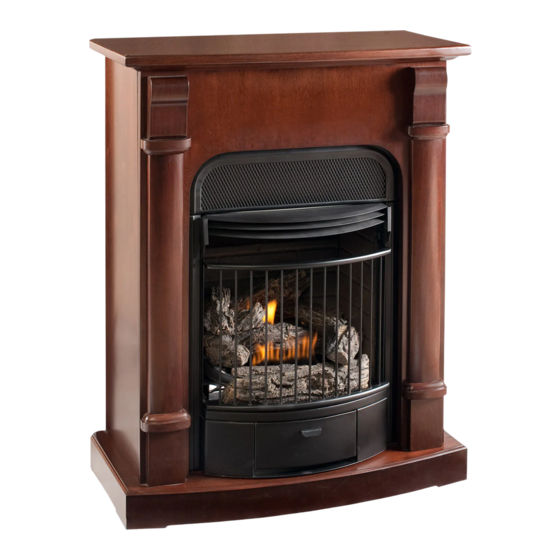
VENT FREE GAS FIREPLACE SYSTEM
MODEL # EDP200T2-JA EDP200T2-MO
EDP200T2-O
EDP200T2CC-DO
WARNING: IF THE INFORMATION IN THIS MANUAL IS NOT FOLLOWED
EXACTLY, A FIRE OR EXPLOSION MAY RESULT CAUSING PROPERTY
DAMAGE, PERSONAL INJURY, OR LOSS OF LIFE.
– Do not store or use gasoline or other flammable vapors and liquids in vicinity of
this or any other appliance.
WHAT TO DO IF YOU SMELL GAS
•
Do not try to light any appliance.
•
Do not touch any electrical switch; do not use any phone in your building.
•
Immediately call your gas supplier from a neighbor's phone. Follow the gas
supplier's instructions.
•
If you cannot reach your gas supplier, call the fire department.
– Installation and service must be performed by a qualified installer, service agency
or the gas supplier.
This is an unvented gas-fired heater. It uses air (oxygen) from the room in which it is
installed. Provisions for adequate combustion and ventilation air must be provided.
Refer to Air For Combustion and Ventilation section on page 8 of this manual.
INSTALLER: Leave this manual with the appliance. CONSUMER: Retain this manual
for future reference.
This appliance may be installed in an aftermarket, permanently located, manufactured
(mobile) home, where not prohibited by local codes. This appliance is only for use with
propane or natural gas. This appliance is equipped with a simple means to switch
between propane and natural gas. Field conversion by any other means including the
use of a kit is not permitted.
Questions about installation, operation, or troubleshooting? Before returning to your retailer, contact our
customer service department at 1-877-886-5989, 8:00 a.m.- 4:30p.m., EST, Monday-Friday or e-mail
customerservice@usaprocom.com.
EDP200T2-C
CAUTION - FOR YOUR SAFETY
WARNING:This appliance is equipped
for (Natural and Propane) gas. Field
conversion is not permitted other than
between natural or propane gases.
Español p. 31
PC-ED200T2651D-1203
Advertisement
Table of Contents

Subscribe to Our Youtube Channel
Related Manuals for Procom EDP200T2-JA


Summary of Contents for Procom EDP200T2-JA
- Page 1 (Natural and Propane) gas. Field conversion is not permitted other than between natural or propane gases. VENT FREE GAS FIREPLACE SYSTEM Español p. 31 MODEL # EDP200T2-JA EDP200T2-MO EDP200T2-O EDP200T2-C EDP200T2CC-DO CAUTION - FOR YOUR SAFETY WARNING: IF THE INFORMATION IN THIS MANUAL IS NOT FOLLOWED EXACTLY, A FIRE OR EXPLOSION MAY RESULT CAUSING PROPERTY DAMAGE, PERSONAL INJURY, OR LOSS OF LIFE.
-
Page 2: Table Of Contents
TABLE OF CONTENTS Important Safety Information................................4 Product Features....................................6 Air For Combustion and Ventilation..............................8 Installation .......................................11 Installing Logs....................................16 Operation......................................17 Care & Maintenance..................................20 Troubleshooting....................................21 Replacement Parts..................................23 WARNING: Read the installation & operation instructions before using this appliance. IMPORTANT: Read instructions and warnings carefully before starting installation. Failure to follow these instructions may result in a possible fire hazard and will void the warranty. - Page 3 MODEL EDP200T2-JA & EDP200T2-MO Input Max. 20,000 BTU/Hr 19,000 BTU/Hr Input Min. 11,500 BTU/Hr 16,500 BTU/Hr Gas Type Natural LP/Propane Ignition Piezo/Automatic Piezo/Automatic Manifold Pressure 4 in.W.C. 9 in.W.C. Inlet Gas Pressure (*For purpose of inlet adjustment) Maximum 10.5 in...
-
Page 4: Important Safety Information
IMPORTANT SAFETY INFORMATION IMPORTANT: Read this owner’s manual carefully and completely before trying to assemble, operate, or service this heater. Improper use of this heater can cause serious injury or death from burns, fire, explosion, electrical shock, and carbon monoxide poisoning. Only a qualified installer, service agent, or local gas supplier may install and service this product. - Page 5 Operating heater above elevations of 4,500 feet could cause pilot outage. To prevent performance problems, do not use propane/LP fuel tank of less than 100 lb. capacity. This heater should not be installed in a bedroom or bathroom. Do not use this heater as a wood-burning heater. Use only the logs provided with the heater. To prevent sooting, follow the instructions in Care and Maintenance (page 20).
-
Page 6: Product Features
PRODUCT FEATURES SAFETY PILOT This heater has a pilot with an Oxygen Depletion Sensing (ODS) safety shutoff system. The ODS/pilot shuts off the heater if there is not enough fresh air. PIEZO IGNITION SYSTEM This heater is equipped with an electronic piezo control system. This system requires AAA batteries (provided). THERMOSTAT HEAT CONTROL The control automatically cycles the burner on and off to maintain a desired room temperature. - Page 7 UNPACKING 1. Remove top inner pack. 2. Tilt carton so that heater is upright. 3. Remove protective side packaging. 4. Slide heater out of carton. 5. Remove protective plastic wrap. 6. Remove screw at top of screen. 7. Hold the screen, lift, and pull forward. 8.
-
Page 8: Air For Combustion And Ventilation
AIR FOR COMBUSTION AND VENTILATION WARNING: If the area in which the heater may be operated does not meet the required volume for indoor combustion air, combustion and ventilation air shall be provided by one of the methods described in the National Fuel Gas Code, ANSI Z223.1/NFPA 54, the International Fuel Gas Code, or applicable local codes. - Page 9 DETERMINING FRESH-AIR FLOW FOR HEATER LOCATION Determining if You Have a Confined or Unconfined Space Use this worksheet to determine if you have a confined or unconfined space. Space: Includes the room in which you will install heater plus any adjoining rooms with door-less passageways or ventilation grills between the rooms.
- Page 10 Ventilation Air From Inside Building Fig. 2 - Ventilation Air from Inside Building This fresh air would come from adjoining unconfined space. When ventilating to an adjoining unconfined space, you must provide two permanent openings: one within 12 inches of the wall connecting the two spaces (see options 1 and 2, Fig.
-
Page 11: Installation
INSTALLATION NOTICE: This heater is intended for use as supplemental heat. Use this heater along with your primary heating system. Do not install this heater as your primary heat source. If you have a central heating system, you may run system’s circulating blower while using heater. - Page 12 CONNECTING TO GAS SUPPLY WARNING: A qualified technician must connect heater to gas supply. Follow all local codes. WARNING: This appliance requires a 3/8 in. NPT inlet connection to pressure regulator (see Fig. 5). CAUTION: Never connect heater directly to the gas supply. This heater requires an external regulator (not supplied). The external regulator between the gas supply and heater must be installed.
- Page 13 CAUTION: Use only new black iron or steel pipe. Internally tinned copper tubing may be used in certain areas. Check your local codes. Use pipe of ½ inch diameter or greater to allow proper volume gas to heater. If pipe is too small, loss of pressure will occur.
- Page 14 CAUTION: Two gas line installations at the same time are prohibited. The access plate to the simple switching means shall not be opened while the heater is in operation. This appliance can be used with propane or natural gas. It is shipped from the factory adjusted for use with propane. Only a qualified installer or service technician can perform gas selection and connecting to gas supply.
- Page 15 CHECKING GAS CONNECTIONS WARNING: Test all gas piping and connections for leaks after installing or servicing. Correct all leaks immediately. WARNING: Never use an open flame to check for a leak. Apply a mixture of liquid soap and water to all joints. If bubbles form, there may be a leak.
-
Page 16: Installing Logs
INSTALLING LOGS WARNING: Failure to position the parts in accordance with these diagrams or failure to use only parts specifically approved with this heater may result in property damage or personal injury. CAUTION: After installation, and periodically thereafter, check to ensure that no flame comes in contact with any log. With the heater set to high, check to see if flames contact any log. -
Page 17: Operation
OPERATION FOR YOUR SAFETY READ BEFORE LIGHTING WARNING: If you do not follow these instructions exactly, a fire or explosion may result causing property damage, personal injury, or loss of life. NOTICE: During initial operation of new heater, burning logs will give off a paper burning smell. Orange flame will also be present. - Page 18 THERMOSTATIC CONTROL OPERATION The thermostatic control used on this model differs from standard thermostats. Standard thermostats simply turn the burner on and off. The thermostat used on this heater senses the room temperature. At times the room may exceed the set temperature. If so, the burner will shut off.
- Page 19 INSPECTING BURNERS Check pilot flame pattern and burner flame patterns often. PILOT FLAME PATTERN 1. Turn control knob to pilot position 2. Inspect pilot flame and refer to Fig. 16 and 17. • Fig. 16 shows a correct pilot flame pattern. •...
-
Page 20: Care & Maintenance
CARE AND MAINTENANCE WARNING: Failure to keep primary air openings of burners clean may result in sooting and property damage. CAUTION: You must keep control areas, burner, and circulating air passageways of heater clean. Inspect these areas of heater before each use. Have heater inspected yearly by a qualified service person. Heater may need more frequent cleaning due to excessive lint from carpeting, bedding material, pet hair, etc. -
Page 21: Troubleshooting
TROUBLESHOOTING WARNING: If you smell gas: • Shut off gas supply. • Do not try to light any appliance. • Do not touch any electrical switch; do not use any phone in your building. • Immediately call your gas supplier from a neighbor’s phone. Follow the gas supplier’s instructions. •... - Page 22 Problem Possible Cause Corrective Action Burner backfiring during 1. Burner orifice is clogged or damaged. 1. Clean burner orifice (see Care and Maintenance, combustion. page 20) or contact customer service. 2. Burner is damaged. 2. Contact dealer or customer service. 3.
-
Page 23: Replacement Parts
REPLACEMENT PARTS NOTE: Use only original replacement parts. This will protect your warranty coverage for parts replaced under warranty. PARTS UNDER WARRANTY Call Customer Service toll free at (877)886-5989 for referral information. When calling Customer Service or your dealer, have ready: •... - Page 24 REPLACEMENT PARTS LIST This list contains replaceable parts used in your heater. When ordering parts, follow the instructions listed under Replacement Parts on page 23 of this manual. Part. Description Part # Burner Assembly PSD20T230 DF ODS NDD0308-400 T-Stat Valve Assembly SIT545-200 Piezo Ignitor PIMSC1-01...
- Page 25 REPLACEMENT PARTS LIST This list contains replaceable parts used in your heater. When ordering parts, follow the instructions listed under Replacement Parts on page 23 of this manual. Part. Description Part # EDP200T2-JA EDP200T2-MO EDP200T2CC-DO EDP200T2-O EDP200T2-C Mantel Assembly ED200L7C-400-JA"...
- Page 27 CORNER MANTEL TRIM CAUTION: If baseboards are installed where the fireplace is intended to be displayed, then the fireplace will not fit flush against the wall. For a proper flush fit, you may need to remove part of the baseboard molding if necessary. HARDWARE CONTENTS Picture Part...
- Page 28 ASSEMBLY INSTRUCTIONS 1. Turn the fireplace top panel over. Using the connector Fig. 1 brackets that are supplied, connect the fireplace top panel to the triangular top triangle panel with ST4 screw - 5/8 in. (CC) as shown in Fig. 1. Fireplace Top Top Triangle Panel Hardware Used...
- Page 29 Fig. 3 3. Drill two holes (5/16 in.) in the corner where the fireplace is to be displayed. Drill the first hole 34 5/16 in. from the ground up; and the second hole 36 in. from the ground up Mitered Corner as shown in Fig.
- Page 30 WARRANTY INFORMATION Keep This Warranty IMPORTANT: We urge you to fill your warranty registration card within TEN(10) days of date of installation, complete with the entire serial number which can be found on the rating plate. Retain this portion of the card for your record. Always specify model and serial numbers when communicating with customer service.
Need help?
Do you have a question about the EDP200T2-JA and is the answer not in the manual?
Questions and answers