Table of Contents
Advertisement
Quick Links
WARNING: If the information in this manual is not
followed exactly, a fire or explosion may result causing
property damage, personal injury or loss of life.
— Do not store or use gasoline or other flammable va-
pors and liquids in the vicinity of this or any other
appliance.
— WHAT TO DO IF YOU SMELL GAS
• Do not try to light any appliance.
• Do not touch any electrical switch; do not use any
phone in your building.
• Immediately call your gas supplier from a neighbor's
phone. Follow the gas supplier's instructions.
• If you cannot reach your gas supplier, call the fire
department.
— Installation and service must be performed by a quali-
fied installer, service agency or the gas supplier.
INSTALLER: Leave this manual with the appliance.
CONSUMER: Retain this manual for future reference.
Questions, problems, missing parts? Before returning to your retailer, call
our customer service department at 1-866-573-0674, 8:00 am - 4:30 pm CST,
Monday through Friday or email contact@usaprocom.com
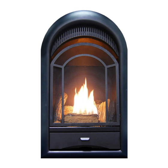
VENT-FREE GAS
FIREPLACE INSERT
OWNER'S OPERATION AND
INSTALLATION MANUAL
MODELS
PCS100T AND PCS150T
Advertisement
Table of Contents

Subscribe to Our Youtube Channel
Related Manuals for Procom PFS PCS100T


Summary of Contents for Procom PFS PCS100T
- Page 1 VENT-FREE GAS FIREPLACE INSERT OWNER’S OPERATION AND INSTALLATION MANUAL MODELS PCS100T AND PCS150T WARNING: If the information in this manual is not followed exactly, a fire or explosion may result causing property damage, personal injury or loss of life. — Do not store or use gasoline or other flammable va- pors and liquids in the vicinity of this or any other appliance.
-
Page 2: Table Of Contents
TABLE OF CONTENTS Safety ............3 Operation ..........17 Qualified Installing Agency ......4 Inspecting Burners........20 Specifications ..........5 Care And Maintenance ......21 Product Features ........5 Troubleshooting ........23 Local Codes..........5 Replacement Parts ........27 Unpacking..........6 Accessories .......... -
Page 3: Safety
SAFETY DANGER: Carbon monoxide WARNING: Do not attempt to poisoning may lead to death! access or change the setting of the fuel selection means. CARBON MONOXIDE POISONING: Early Access to and adjustment of signs of carbon monoxide poisoning resemble the flu, with headaches, dizziness or nausea. the fuel selection means must If you have these signs, the heater may not be only be performed by a qualified... -
Page 4: Qualified Installing Agency
SAFETY Air for Combustion and Ventilation, pages WARNING: Do not allow fans 7 and 8. If heater keeps shutting off, see to blow directly into fireplace. Troubleshooting, page 23. 4. Keep all air openings in front and bottom Avoid any drafts that alter burner of heater clear and free of debris. -
Page 5: Specifications
SPECIFICATIONS Model PCS100T PCS150T Gas Type Natural Gas Propane Gas Natural Gas Propane Gas Maximum Input Rating 10,000 Btu/Hr 10,000 Btu/Hr 15,000 Btu/Hr 15,000 Btu/Hr Minimum Input Rating 5,000 Btu/Hr 8,000 Btu/Hr 7,000 Btu/Hr 11,000 Btu/Hr Pressure Regulator Setting 4" W.C. 9"... -
Page 6: Unpacking
UNPACKING 1. Remove top inner pack. 7. Remove log set by cutting plastic ties. 2. Tilt carton so that heater is upright. 8. Carefully unwrap log. 3. Remove protective side packaging. 9. Check for any shipping damage. If heater or log is damaged, promptly inform your 4. -
Page 7: Air For Combustion And Ventilation
QUALIFIED INSTALLING AGENCY Only a qualified agency should install and a) Installing, testing, or replacing gas piping replace gas piping, gas utilization equipment or accessories, and repair and equipment ser- b) Connecting, installing, testing, repairing, vicing. The term “qualified agency” means any or servicing equipment;... - Page 8 AIR FOR COMBUSTION AND VENTILATION VENTILATION AIR Ventilation Air From Inside Building Ventilation Air From Outdoors Provide extra fresh air by using ventilation This fresh air would come from an adjoining grills or ducts. You must provide two perma- unconfined space. When ventilating to an nent openings: one within 12"...
-
Page 9: Installation
INSTALLATION IMPORTANT: Vent-free heaters add moisture NOTICE: This heater is intended to the air. Although this is beneficial, installing for use as supplemental heat. heater in rooms without enough ventilation air Use this heater along with your may cause mildew to form too much moisture. primary heating system. - Page 10 INSTALLATION GAS SELECTION Yellow Natural Gas Blue Propane Gas This appliance is factory preset Plunger Underneath Plunger DO NOT for propane gas. No changes Metal Cap REMOVE! are required for connecting to propane. Only a qualified installer or service technician can perform gas selection and connecting to gas supply.
- Page 11 INSTALLATION FOR NATURAL GAS Use only the metal cap. DO NOT INSTALLATION: YELLOW use an off the shelf 3/8" NPT pipe 1. Remove the metal cap installed over the cap. This will damage the plung- NG regulator inlet. ers located inside the regulator. DO NOT TRY TO REMOVE THE PLUNGERS FROM INSIDE THE REGULATOR.
- Page 12 INSTALLATION BUILT-IN FIREPLACE INSTALLATION WARNING: Do not allow any combustible materials to overlap the firebox front. WARNING: Do not allow combustible or noncombustible materials to cover any necessary openings like louvered slots. 1/4" Clearance to Facia WARNING: Never modify or 3/8"...
- Page 13 INSTALLATION 3. Attach gas line to fireplace gas regulator. See Connecting to Gas Supply, page 13. 4. Check all gas connections for leaks. See 90° Checking Gas Connections, page 15. IMPORTANT: When finishing your firebox, combustible materials such as wall board, gypsum board, sheet rock, drywall, plywood, etc, must have 1/2"...
- Page 14 INSTALLATION CONNECTING TO GAS SUPPLY WARNING: A qualified ser- CAUTION: Avoid damage to vice technician must connect regulator. Hold gas regulator heater to gas supply. Follow all with wrench when connecting local codes. into gas piping and/or fittings. WARNING: This appliance CAUTION: Use pipe joint requires a 3/8"...
- Page 15 INSTALLATION The installer must supply an external regula- Install sediment trap in supply line as shown tor. The external regulator will reduce incom- in Figure 12. Place sediment trap where it is ing gas pressure. You must reduce incoming within reach for cleaning. Place sediment trap gas pressure to between 11"...
- Page 16 INSTALLATION CHECKING GAS CONNECTIONS Test Pressures Equal To or Less Than WARNING: Test all gas piping 1/2 PSIG (3.5 kPa) and connections for leaks after 1. Close equipment shutoff valve (see Fig- installing or servicing. Correct ure 15). all leaks at once. 2.
- Page 17 INSTALLATION PRESSURE TESTING HEATER GAS CONNECTIONS 1. Open equipment shutoff valve (see Figure 17, page 15). Apply a noncorrosive leak 15, page 16). detection fluid to all joints. Bubbles form- ing show a leak. 2. Open main gas valve located on or near gas meter for natural gas or open propane 5.
-
Page 18: Operation
INSTALLATION BATTERY INSTRUCTIONS CAUTION: Do not dispose of batteries in fire, batteries may explode or leak. Battery • Battery is included. Positive • Remove battery when depleted. • Be sure to observe proper polarity (+/-) when installing or replacing the battery. Damage due to improper battery installation may void the warranty on the product. - Page 19 OPERATION LIGHTING INSTRUCTIONS Note: If pilot does not stay lit, refer to WARNING: You must oper- Troubleshooting, pages 23 though 26. ate this heater with the screen Also contact a qualified service technician in place. Make sure screen is or gas supplier for repairs. Until repairs are made, light pilot with match.
-
Page 20: Inspecting Burners
OPERATION THERMOSTAT CONTROL OPERATION The thermostatic control used on this model room temperature drops below the set tem- differs from standard thermostats. Standard perature. The control knob can be set to any thermostats simply turn the burner on and off. comfort level between HIGH (5) and LOW (1). -
Page 21: Care And Maintenance
INSPECTING BURNERS Natural Gas Shown Natural Gas Shown 3-3.5" WC 8-11" WC 3-3.5" WC 8-11" WC Approx. 3"-6" Above Top of Logs Figure 24 - Correct Pilot Flame Pattern Figure 25 - Incorrect Pilot Flame Pattern (Natural Gas shown) (Natural Gas shown) BURNER FLAME PATTERN Figure 26 shows a correct burner flame pattern. - Page 22 CARE AND MAINTENANCE CLEANING BURNER PILOT AIR INLET HOLE 4. Check the injector holder located at the We recommend that you clean the unit ev- end of the burner tube again. Remove any ery 2,500 hours of operation or every three large particles of dust, dirt, lint, or pet hair months.
-
Page 23: Troubleshooting
TROUBLESHOOTING WARNING: If you smell gas: • Shut off gas supply. • Do not try to light any appliance. • Do not touch any electrical switch; do not use any phone in your building. • Immediately call your gas supplier from a neighbor’s phone. Fol- low the gas supplier’s instructions. - Page 24 TROUBLESHOOTING Problem Possible Cause Corrective Action When ignitor button is 1. Low battery. 1. Replace battery. pressed in, there is no 2. Ignitor electrode is not con- 2. Reattach ignitor cable spark at ODS/pilot nected to ignitor cable. 3. Ignitor cable is pinched or 3.
- Page 25 TROUBLESHOOTING Problem Possible Cause Corrective Action Burner(s) does not light 1. Burner orifice is clogged. 1. Clean burner orifice (see after ODS/pilot is lit Care and Maintenance, page 21). 2. Inlet gas pressure is too low. 2. Contact local gas supplier. 3.
- Page 26 TROUBLESHOOTING Problem Possible Cause Corrective Action Heater produces a whis- 1. Turning control knob to high 1. Turn control knob to low (1) tling noise when burner (5) position when burner is position and let warm up for is lit. cold.
-
Page 27: Replacement Parts
1-866-573-0674 for referral information. ACCESSORIES Purchase these heater accessories from your local dealer. If they can not supply these acces- sories, contact ProCom Heating, Inc. at 1-866-573-0674 for information. EQUIPMENT SHUTOFF VALVE For all models. Equipment shutoff valve with 1/2" NPT tap. -
Page 28: Parts
PARTS MODEL PCS100T & PCS150T www.usaprocom.com 200159-01B... - Page 29 PARTS MODEL PCS100T & PCS150T This list contains replaceable parts for your heater. When ordering replacement parts, follow the instructions listed under Replacement Parts on page 27 of this manual. ITEM PART # DESCRIPTION 150PCS102B-02 Screen Assembly 15T1500B-01 Gas Train Assembly PIMDN1-01 Ignitor 15T1004B-01...
- Page 30 NOTES ________________________________________________________________ ________________________________________________________________ ________________________________________________________________ ________________________________________________________________ ________________________________________________________________ ________________________________________________________________ ________________________________________________________________ ________________________________________________________________ ________________________________________________________________ ________________________________________________________________ ________________________________________________________________ ________________________________________________________________ ________________________________________________________________ ________________________________________________________________ ________________________________________________________________ ________________________________________________________________ ________________________________________________________________ ________________________________________________________________ ________________________________________________________________ ________________________________________________________________ ________________________________________________________________ ________________________________________________________________ ________________________________________________________________ ________________________________________________________________ ________________________________________________________________ www.usaprocom.com 200159-01B...
- Page 31 NOTES ________________________________________________________________ ________________________________________________________________ ________________________________________________________________ ________________________________________________________________ ________________________________________________________________ ________________________________________________________________ ________________________________________________________________ ________________________________________________________________ ________________________________________________________________ ________________________________________________________________ ________________________________________________________________ ________________________________________________________________ ________________________________________________________________ ________________________________________________________________ ________________________________________________________________ ________________________________________________________________ ________________________________________________________________ ________________________________________________________________ ________________________________________________________________ ________________________________________________________________ ________________________________________________________________ ________________________________________________________________ ________________________________________________________________ ________________________________________________________________ ________________________________________________________________ www.usaprocom.com 200159-01B...
-
Page 32: Warranty
We make no other warranty, expressed or implied. NEW PRODUCTS Standard Warranty: ProCom Heating, Inc. warrants this product to be free from defects in materials and components for ONE (1) year from the date of first purchase, provided that the product has been properly installed by a qualified installer in accordance with all local codes and instructions furnished with the unit, operated and maintained in accordance with all applicable instructions.
Need help?
Do you have a question about the PFS PCS100T and is the answer not in the manual?
Questions and answers
Where is the battery located on the Procom pcs100t gas log fireplace?
The battery for the Procom PFS PCS100T gas log fireplace is located in the ignitor. To install or replace the battery, unscrew the ignitor cap, insert a AAA battery with the positive (+) side pointing out, and then replace the cap.
This answer is automatically generated