Table of Contents
Advertisement
WARNING: If the information in this manual is not
followed exactly, a fire or explosion may result causing
property damage, personal injury or loss of life.
— Do not store or use gasoline or other flammable va-
pors and liquids in the vicinity of this or any other
appliance.
— WHAT TO DO IF YOU SMELL GAS
• Do not try to light any appliance.
• Do not touch any electrical switch; do not use any
phone in your building.
• Immediately call your gas supplier from a neighbor's
phone. Follow the gas supplier's instructions.
• If you cannot reach your gas supplier, call the fire
department.
— Installation and service must be performed by a quali-
fied installer, service agency or the gas supplier.
WARNING: This appliance is equipped for natural and
propane/LP gas. Field conversion is not permitted other
than between natural or propane.LP gases.
Questions, problems, missing parts? Before returning to your retailer, call
our customer service department at 1-866-573-0674, 8:00 am - 4:30 pm CST,
Monday through Friday or email customerservice@usaprocom.com
VENT-FREE GAS SYSTEM
OWNER'S OPERATION
AND INSTALLATION
MANUAL
MODELS
FBD400RTCC-M-HC/MO
FBD400TCC-M-HC/MO
PFS
®
US
Advertisement
Table of Contents

Subscribe to Our Youtube Channel
Related Manuals for Procom FBD400RTCC-M-HC/MO


Summary of Contents for Procom FBD400RTCC-M-HC/MO
- Page 1 VENT-FREE GAS SYSTEM OWNER'S OPERATION AND INSTALLATION MANUAL MODELS FBD400RTCC-M-HC/MO FBD400TCC-M-HC/MO ® WARNING: If the information in this manual is not followed exactly, a fire or explosion may result causing property damage, personal injury or loss of life. — Do not store or use gasoline or other flammable va- pors and liquids in the vicinity of this or any other appliance.
-
Page 2: Table Of Contents
TABLE OF CONTENTS Safety ............3 Operation ..........18 Specifications ..........5 Inspecting Burners........24 Qualified Installing Agency ......5 Care And Maintenance ......25 Product Features ........5 Troubleshooting ........27 Product Identification ......... 6 Parts ............30 Unpacking..........6 Replacement Parts ........ -
Page 3: Safety
SAFETY IMPORTANT: Read this owner’s WARNING: Any change to manual carefully and completely this heater or its controls can before trying to assemble, op- be dangerous. erate, or service this heater. Improper use of this heater can WARNING: Do not use a cause serious injury or death blower insert, heat exchange from burns, fire, explosion,... - Page 4 SAFETY 1. Do not place Propane/LP supply tank(s) 10. Turn off and unplug heater and let cool inside any structure. Propane/LP supply before servicing. Only a qualified service tank(s) must be placed outdoors. person should service and repair heater. 2. This heater should not be installed in a 11.
-
Page 5: Specifications
9" W.C. Inlet Gas Pressure* Max. 10.5" W.C. Max. 14" W.C. (inches of water) Min. 5" W.C. Min. 11" W.C. MODELS FBD400RTCC-M-HC/MO Gas Type Natural Propane/LP Maximum Input Rating 32,000 BTU/Hr 32,000 BTU/Hr Minimum Input Rating Regulator Pressure Setting 4" W.C. -
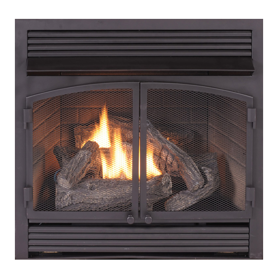
Page 6: Product Identification
PRODUCT IDENTIFICATION Hood Screen Logs Heater Controls (Inside Panel) Figure 1 - Vent-Free Fireplace Insert UNPACKING 1. Remove top inner pack. 6. Hold the screen, lift, and pull forward. 2. Tilt carton so that heater is upright. 7. Remove log set by cutting plastic ties. 3. -
Page 7: Water Vapor: A By-Product Of Unvented Room Heaters
WATER VAPOR: A BY-PRODUCT OF UNVENTED ROOM HEATERS Water vapor is a by-product of gas combus- The following steps will help ensure that water tion. An unvented room heater produces ap- vapor does not become a problem. proximately one (1) ounce (30 mL) of water 1. - Page 8 AIR FOR COMBUSTION AND VENTILATION Unusually Tight Construction The air that leaks around doors and windows c. caulking or sealants are applied to areas may provide enough fresh air for combustion such as joints around window and door and ventilation. However, in buildings of un- frames, between sole plates and floors, usually tight construction, you must provide between wall-ceiling joints, between wall...
-
Page 9: Ventilation Air From Inside Building
AIR FOR COMBUSTION AND VENTILATION The space in the above example is a confined Btu/Hr the space can support, the space space because the actual Btu/Hr used is more is an unconfined space. You will need no than the maximum Btu/Hr the space can sup- additional fresh air ventilation. -
Page 10: Installation
INSTALLATION NOTICE: This heater is intended WARNING: Never install the for use as supplemental heat. heater Use this heater along with your • in a bedroom or bathroom primary heating system. Do not • in a recreational vehicle install this heater as your pri- •... -
Page 11: Gas Supply
INSTALLATION GAS SELECTION For changing from propane to This appliance is factory natural gas supply: preset for propane/LP gas. 1. Remove bottom screw from cover plate No changes are required for located on back side of heater (see Figure 4). Rotate to expose fuel selection device. connecting to propane/LP. - Page 12 LP position. Do not existing fireplace. Install this firebox only in operate heater between locked positions. a ProCom Heating, Inc. mantel accessory 3. Rotate and close cover over fuel selection approved for this product. device and reinstall screw.
- Page 13 INSTALLATION CONNECTING TO GAS SUPPLY WARNING: A qualified ser- CAUTION: For natural gas, vice technician must connect check your gas line pressure heater to gas supply. Follow all before connecting heater to gas local codes. line. Gas line pressure must be no greater than 10.5"...
- Page 14 INSTALLATION Typical Inlet Pipe Diameters reduce incoming gas pressure to between 11" Use 3/8" black iron pipe or greater. Installa- and 14" of water. If you do not reduce incom- tion must include an equipment shutoff valve, ing gas pressure, heater regulator damage union, and plugged 1/8"...
-
Page 15: Checking Gas Connections
INSTALLATION CHECKING GAS CONNECTIONS Open Equipment WARNING: Test all gas piping Shutoff Valve and connections, internal and external to unit, for leaks after installing or servicing. Correct Closed all leaks at once. Figure 10 - Equipment Shutoff Valve Equipment WARNING: Never use an open Propane/LP Shutoff Valve Supply Tank... -
Page 16: Installing Logs
INSTALLATION INSTALLING LOGS 6. Insert the pin on log #6 into the hole on WARNING: Failure to posi- log #3 (see Figures 15 and 16, page 17). tion the parts in accordance IMPORTANT: Make sure logs do not cover with these diagrams or failure any burner ports. - Page 17 INSTALLATION Hole for Log #6 Pin for Log #5 Log #5 Log #6 Log #4 Figure 16 - Installing Log #5 and #6 Figure 15 - Installing Log #4 INSTALLING BATTERIES Ignitor CAUTION: Do not mix old and Unscrew ignitor cap and install a AAA battery new batteries.
-
Page 18: Operation
OPERATION FOR YOUR SAFETY READ BEFORE LIGHTING not use any phone in your building. WARNING: If you do not fol- • Immediately call your gas supplier low these instructions exactly, from a neighbor’s phone. Follow the a fire or explosion may result gas supplier’s instructions. -
Page 19: To Turn Off Gas To Appliance
OPERATION 7. With control knob pressed in, push Note: Please wait one minute after shut- down and release ignitor button. This ting off heater to allow the control valve will light pilot. The pilot is attached to to reset before starting again. the rear of the burner. -
Page 20: Lighting Instructions
OPERATION MODELS FBD400RTCC-M-HC/MO LIGHTING INSTRUCTIONS Note: If pilot does not stay lit, refer to WARNING: You must oper- Troubleshooting, pages 27 though 29. ate this heater with the screen Also contact a qualified service technician or gas supplier for repairs. Until repairs in place. -
Page 21: Remote Control System
OPERATION CAUTION: Do not try to ad- WARNING: If input gas just heating levels by using the type is NG, make sure NG pilot equipment shutoff valve. burner ignites. If input gas type is LP, make sure LP pilot burner ignites. - Page 22 OPERATION Key Settings Setting°F/°C Scale ON - Operates unit to on position, manually The factory setting for temperature is °F. To operated solenoid ON. change this setting to °C, press the ON key and the OFF key on the remote control at the OFF - Operates unit to off position, manually same time (see Figure 22).
- Page 23 OPERATION REMOTE CONTROL OPERATION 1. Press the MODE key until the LCD screen NOTES shows the word ROOM. The remote is now in the thermostatic mode. The Thermo Feature on the transmitter op- erates the appliance whenever the ROOM 2. Press and hold the SET key until the de- TEMPERATURE varies a certain number of sired set temperature is reached.
-
Page 24: Inspecting Burners
INSPECTING BURNERS IMPORTANT: Owner’s should check pilot flame pattern and burner flame pattern often. Incorrect flame patterns indicate the need for cleaning (see Care and Maintenance, page 25) or service. WARNING: Only a qualified service person should service and repair heater. This includes maintenance requiring replacement or alteration of components. -
Page 25: Care And Maintenance
CARE AND MAINTENANCE WARNING: Turn off heater and let cool before servicing. CAUTION: You must keep control areas, burner, and circulating air passageways of heater clean. Inspect these areas of heater before each use. Have heater inspected yearly by a qualified service techni- cian. - Page 26 CARE AND MAINTENANCE ODS/PILOT Ignitor Use a vacuum cleaner, pressurized air, or a Electrode small, soft bristled brush to clean. Natural Gas Thermocouple Burner A yellow tip on the pilot flame indicates dust and dirt in the pilot assembly. There is a small Propane/LP pilot air inlet hole about 2"...
-
Page 27: Troubleshooting
TROUBLESHOOTING WARNING: If you smell gas: • Shut off gas supply. • Do not try to light any appliance. • Do not touch any electrical switch; do not use any phone in your building. • Immediately call your gas supplier from a neighbor’s phone. Fol- low the gas supplier’s instructions. - Page 28 TROUBLESHOOTING Problem Possible Cause Corrective Action ODS/pilot lights but flame 1. Control knob is not fully 1. Press in control knob fully. goes out when control pressed in. knob is released. 2. Control knob is not pressed 2. After ODS/pilot lights, keep in long enough.
- Page 29 TROUBLESHOOTING Problem Possible Cause Corrective Action Slight smoke or odor 1. Residues from manufactur- 1. Problem will stop after a few during initial operation. ing process. hours of operation. Heater produces a whis- 1. Turning control knob to high 1. Turn control knob to low tling noise when burner position when burner is cold.
-
Page 30: Parts
PARTS MODELS FBD400RTCC-M-HC/MO FBD400TCC-M-HC/MO PIL OT TEMP www.usaprocom.com 200020-01A... - Page 31 PARTS MODELS FBD400RTCC-M-HC/MO FBD400TCC-M-HC/MO This list contains replaceable parts used in your heater. When ordering parts, follow the instructions listed under Replacement Parts on page 32 of this manual. ITEM FBD400TCC FBD400RTCC-2 DESCRIPTION FHL008-02D FHL008-02D Hood FBB102 FBB102 Louver FBB104BL...
-
Page 32: Replacement Parts
1-866-573-0674 for referral information. ACCESSORIES Purchase these heater accessories from your local dealer. If they can not supply these acces- sories, contact ProCom Heating, Inc. at 1-866-573-0674 for information. EQUIPMENT SHUTOFF VALVE For all models. Equipment shutoff valve with 1/8" NPT tap. -
Page 33: Service Hints
You may feel your gas pressure is too low. If so, contact your local gas supplier. TECHNICAL SERVICE You may have further questions about installation, operation, or troubleshooting. If so, contact ProCom Heating, Inc. at 1-866-573-0674. When calling, please have your model and serial numbers of your heater ready. www.usaprocom.com... - Page 34 NOTES ________________________________________________________________________ ________________________________________________________________________ ________________________________________________________________________ ________________________________________________________________________ ________________________________________________________________________ ________________________________________________________________________ ________________________________________________________________________ ________________________________________________________________________ ________________________________________________________________________ ________________________________________________________________________ ________________________________________________________________________ ________________________________________________________________________ ________________________________________________________________________ ________________________________________________________________________ ________________________________________________________________________ ________________________________________________________________________ ________________________________________________________________________ ________________________________________________________________________ ________________________________________________________________________ ________________________________________________________________________ ________________________________________________________________________ ________________________________________________________________________ ________________________________________________________________________ ________________________________________________________________________ ________________________________________________________________________ ________________________________________________________________________ ________________________________________________________________________ ________________________________________________________________________ ________________________________________________________________________ ________________________________________________________________________ ________________________________________________________________________ ________________________________________________________________________ ________________________________________________________________________ www.usaprocom.com 200020-01A...
- Page 35 NOTES ________________________________________________________________________ ________________________________________________________________________ ________________________________________________________________________ ________________________________________________________________________ ________________________________________________________________________ ________________________________________________________________________ ________________________________________________________________________ ________________________________________________________________________ ________________________________________________________________________ ________________________________________________________________________ ________________________________________________________________________ ________________________________________________________________________ ________________________________________________________________________ ________________________________________________________________________ ________________________________________________________________________ ________________________________________________________________________ ________________________________________________________________________ ________________________________________________________________________ ________________________________________________________________________ ________________________________________________________________________ ________________________________________________________________________ ________________________________________________________________________ ________________________________________________________________________ ________________________________________________________________________ ________________________________________________________________________ ________________________________________________________________________ ________________________________________________________________________ ________________________________________________________________________ ________________________________________________________________________ ________________________________________________________________________ ________________________________________________________________________ ________________________________________________________________________ ________________________________________________________________________ www.usaprocom.com 200020-01A...
-
Page 36: Warranty
We make no other warranty, expressed or implied. LIMITED WARRANTY ProCom Heating, Inc. warrants this product to be free from defects in materials and components for ONE (1) year from the date of first purchase, provided that the product has been properly installed by a qualified installer in accordance with all local codes and instructions furnished with the unit, operated and main- tained in accordance with all applicable instructions.
Need help?
Do you have a question about the FBD400RTCC-M-HC/MO and is the answer not in the manual?
Questions and answers