Table of Contents
Advertisement
Quick Links
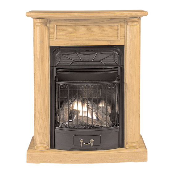
VENT-FREE FIREPLACE
MODEL # EDP200T2-O
EDP200T2-C
EDS200T2-HC
WARNING: IF THE INFORMATION IN THIS MANUAL IS NOT FOLLOWED
EXACTLY, A FIRE MAY RESULT CAUSING PROPERTY DAMAGE, PERSONAL
INJURY, OR LOSS OF LIFE.
–
Do not store or use gasoline or other flammable vapors and liquids in vicinity of
this or any other appliance.
WHAT TO DO IF YOU SMELL GAS
· Do not try to light any appliance.
· Do not touch any electrical switch; do not use any phone in your building.
· Immediately call your gas supplier from a neighbor's phone. Follow the gas
supplier's instructions.
· If you cannot reach your gas supplier, call the fire department.
– Installation and service must be performed by a qualified installer, service agency
or the gas supplier.
This is an unvented gas-fired heater. It uses air (oxygen) from the room in which it is
installed. Provisions for adequate combustion and ventilation air must be provided.
Refer to Air for Combustion and Ventilation section on page 7 of this manual.
INSTALLER: DO NOT DISCARD THIS MANUAL – LEAVE FOR HOMEOWNER'S
FUTURE REFERENCE.
This appliance may be installed in an aftermarket*, permanently located manufactured
(mobile) home, where not prohibited by local codes. This appliance is only for use with
the type of gas indicated on the rating plate. This appliance is not convertible for use
with other gases.
Questions about installation, operation, or troubleshooting? Before returning to your retailer, contact our
customer service department at 1-877-886-5989, 8:00 a.m. - 4:30 p.m., EST, Monday-Friday or e-mail
customerservice@usaprocom.com
CAUTION – FOR YOUR SAFETY
WARNING: This appliance is
equipped for (Natural and
Propane) gas. Field conversion is
not permitted other than between
natural or propane gases.
ED200T2 651-0903
Advertisement
Table of Contents

Subscribe to Our Youtube Channel
Related Manuals for Procom EDP200T2-O


Summary of Contents for Procom EDP200T2-O
- Page 1 VENT-FREE FIREPLACE WARNING: This appliance is equipped for (Natural and MODEL # EDP200T2-O Propane) gas. Field conversion is EDP200T2-C not permitted other than between natural or propane gases. EDS200T2-HC CAUTION – FOR YOUR SAFETY WARNING: IF THE INFORMATION IN THIS MANUAL IS NOT FOLLOWED EXACTLY, A FIRE MAY RESULT CAUSING PROPERTY DAMAGE, PERSONAL INJURY, OR LOSS OF LIFE.
-
Page 2: Table Of Contents
IMPORTANT: Read instructions and warnings carefully before starting installation. Failure to follow these instructions may result in a possible fire hazard and will void the warranty. PRODUCT SPECIFICATIONS MODEL EDP200T2-C & EDP200T2-O EDS200T2-HC Input Max. 20,000 BTU/Hr 19,000 BTU/Hr 20,000 BTU/Hr 19,000 BTU/Hr Input Min. -
Page 3: Important Safety Information
IMPORTANT SAFETY INFORMATION IMPORTANT: Read this owner’s manual carefully and completely before trying to assemble, operate, or service this heater. Improper use of this heater can cause serious injury or death from burns, fire, explosion, electrical shock, and carbon monoxide poisoning. Only a qualified installer, service agent, or local gas supplier may install and service this product. -
Page 4: Qualified Installing Agency
Do not place Propane/LP supply tank(s) inside any structure. Propane/LP supply tank(s) must be placed outdoors. This heater shall not be installed in a bedroom or bathroom. Do not use this heater as a wood-burning heater. Use only the logs provided with the heater. Do not add extra logs or ornaments such as pine cones, vermiculite, or rock wool. -
Page 5: Product Features
PRODUCT FEATURES SAFETY PILOT This heater has a pilot with an Oxygen Depletion Sensing (ODS) safety shutoff system. ODS/pilot is a required feature for vent-free room heaters. ODS/pilot shuts off the heater if there is not enough fresh air. PIEZO IGNITION SYSTEM This heater is equipped with an electronic piezo control system. -
Page 6: Product Identification
UNPACKING Remove top inner pack. Tilt carton so that heater is upright. Remove protective side packaging. Slide heater out of carton. Remove protective plastic wrap. Remove screw at top of screen. Hold the screen lift and pull forward. Remove log set by cutting plastic. Carefully unwrap log. -
Page 7: Air For Combustion And Ventilation
AIR FOR COMBUSTION AND VENTILATION WARNING : This heater shall not be installed in a confined space or unusually tight construction unless provisions are provided for adequate combustion and ventilation air. Read the following instructions to insure proper fresh air for this and other fuel-burning appliances in your home. PRODUCING ADEQUATE VENTILATION This heater shall not be installed in a room or space unless the required volume of indoor combustion air is provided by the method described in the NATIONAL FUEL GAS CODE, ANSI Z223.1/NFPA 54, the... - Page 8 Divide the space volume by 50 cubic feet to determine the maximum BTU/hr the space can support. (Volume of space) ÷ 50 cu. ft. = (Maximum BTU/hr the space can support) Example: 2560 cu. ft. (volume of space) ÷ 50 cu. ft. = 51.2 or 51,200(maximum BTU/hr the space can support) Add the BTU/hr of all fuel burning appliances in the space.
-
Page 9: Installation
Ventilation Air from Outdoors Figure 3 – Ventilation Air from Outdoors Provide extra fresh air by using ventilation grills or ducts. You must provide two permanent " openings: one within 12 of the ceiling and one " within 12 of the floor. Connect these items directly to the outdoors or spaces open to the outdoors. -
Page 10: Connecting To Gas Supply
Figure 4 – Minimum Clearance to Wall and Ceiling Minimum Wall and Ceiling Clearances (See Figure 4) Clearances from outermost point of fireplace to any combustible side wall should not be less than 12 inches. Clearances from the fireplace to the ceiling should not be less than 48 inches. - Page 11 INSTALLATION CONTINUED Figure 6 – External Regulator with Vent Pointing Down The installer must supply an external regulator. The external regulator will reduce incoming gas pressure. You must reduce incoming gas pressure to between 11 and 14 inches of water column for propane and between 5 and 10.5 inches of water column for natural gas.
- Page 12 INSTALLATION CONTINUED CAUTION: Two gas line installations at the same time are forbidden. Do not open cover while the heater is running. Heater is pre-set at factory for propane gas, no changes are required for connecting to propane. Only a qualified installer or service technician can perform gas selection and connecting to gas supply.
-
Page 13: Checking Gas Connections
CHECKING GAS CONNECTIONS WARNING: Test all gas piping and connections for leaks after installing or servicing. Correct all leaks immediately. Pressure Testing Gas Supply Piping System Test Pressures In Excess Of ½ PSIG (3.5kPa) Disconnect heater with its appliance main gas valve (control valve) and equipment shutoff valve from gas supply piping system. -
Page 14: Installing Logs
INSTALLING LOGS Figure 13 -Installing Log Set WARNING: Failure to position the parts in accordance with these diagrams or failure to use only parts may result in property damage or personal injury. CAUTION: After installation and periodically thereafter, check to ensure that no flame comes in contact with any log. - Page 15 STEP 3: Insert the two pins on the bottom of log 3 STEP 4: Insert the recessed hole on the bottom of log 4 into the two holes on firebox floor. onto the pin on log 1, with the other end of log 4 placed on log 2, as shown.
-
Page 16: Operating Heater
OPERATING HEATER FOR YOUR SAFETY READ BEFORE LIGHTING WARNING: If you do not follow these instructions exactly, a fire or explosion may result causing property damage, personal injury or loss of life. NOTICE: fireplace During initial operation of the new , burning logs will give off a paper-burning smell. -
Page 17: Lighting Instructions
LIGHTING INSTRUCTIONS STOP! Read the safety information on page 3. Unscrew ignitor cap and install a AAA type battery with its anode (“+”) pointing out. Replace cap Make sure equipment shutoff valve is fully open. Warning: You must operate this fireplace with the fireplace screen in place. Make sure fireplace screen is installed before running fireplace. -
Page 18: Inspecting Burners
MANUAL LIGHTING PROCEDURE (Match Light) Remove screen by lifting and pulling forward. Follow steps 1 through 7 under MANUAL OPERATING Lighting Instructions. With Control Knob in PILOT position, strike match, and hold near pilot. Press in Control Knob; pilot should light. -
Page 19: Care And Maintenance
CARE AND MAINTENANCE WARNING: Disconnect power before attempting any maintenance or cleaning to reduce the risk of fire, electric shook or personal injury. Turn off heater and let cool before cleaning. WARNING: Failure to keep primary air openings of burners clean may result in sooting and property damage. -
Page 20: Troubleshooting
TROUBLESHOOTING NOTE: Turn the control knob to “OFF” position first and wait for one minute. Then turn the control knob to the “ON” position. Please wait for one minute to allow valve to reset. WARNING: If you smell gas · Shut off gas supply. - Page 21 OBSERVED REMEDY POSSIBLE CAUSE PROBLEM ODS/pilot lights but 1. Control knob is not fully pressed in. Press in control knob fully. flame goes out when 2. Control knob is not pressed in long After ODS/pilot lights, keep control knob control knob is enough.
- Page 22 OBSERVED REMEDY POSSIBLE CAUSE PROBLEM White powder 1. When heated, the vapors from furniture 1. Turn heater off when using furniture residue forming polish, wax, carpet cleaners, etc., turn polish, wax, and carpet cleaner or similar within burner box into white powder residue. products.
-
Page 23: Replacement Parts
REPLACEMENT PARTS NOTE: Use only original replacement parts. This will protect your warranty coverage for parts replaced under warranty. PARTS UNDER WARRANTY Contact authorized dealers of this product. If they can’t supply original replacement parts, call Customer Service toll free at 1-877-886-5989 for referral information. When calling Customer Service or your dealer, have ready: ·... - Page 24 PARTS LIST This list contains replaceable parts used in your heater. When ordering parts, follow the instructions listed under Replacement Parts on page 23 of this manual. KEY NO. PART NUMBER DESCRIPTION PSD20T230 Burner Assembly NDD0308 DF ODS SIT545-200 T-Stat Valve AL092-01 Piezo Ignitor RV83FI-4/9...
- Page 25 PARTS LIST EDP200T2-O & EDP200T2-C This list contains replaceable parts used in your heater. When ordering parts, follow the instructions listed under Replacement Parts on page 23 of this manual. Part Number Description EDP200T-O EDP200T-C ED200L14B-01-O ED200L14B-01-C ED200L14-05-O Decorative Column...
- Page 26 EDP200T2-O & EDP200T2-C...
- Page 27 PARTS LIST EDS200T2-HC This list contains replaceable parts used in your heater. When ordering parts, follow the instructions listed under Replacement Parts on page 23 of this manual. Key No. Part Number Description ED200L12B-01-HC ED200L12B-02-HC Panel ED200L12B-03-HC Pedestal ED200L12B-04-HC Right Panel ED200L12B-05-HC Left Panel ED200T2002...
Need help?
Do you have a question about the EDP200T2-O and is the answer not in the manual?
Questions and answers